Kenwood TK-7102H Service Manual
Hide thumbs
Also See for TK-7102H:
- Service manual (41 pages) ,
- Instruction manual (16 pages) ,
- Specification (2 pages)
Table of Contents
Advertisement
VHF FM TRANSCEIVER
TK-7102H
SERVICE MANUAL
REVISED
This service manual applies to products with 50300001 or subsequent serial numbers.
In terms of the products with the serial numbers earlier than 50300001, refer to the TK-7102H service manual as per part No.
B51-8610-00 and B51-8627-00.
Chassis
(A10-4048-21)
GENERAL .................................................. 2
SYSTEM SET-UP ...................................... 3
OPERATING FEATURES .......................... 4
REALIGNMENT ......................................... 8
INSTALLATION ....................................... 11
DISASSEMBLY FOR REPAIR ................. 13
CIRCUIT DESCRIPTION .......................... 14
SEMICONDUCTOR DATA ...................... 18
COMPONENTS DESCRIPTION .............. 20
PARTS LIST ............................................. 21
EXPLODED VIEW .................................... 27
Service Manual List
Title
Parts number
TK-7102H
B51-8610-00
TK-7102H
B51-8627-00
TK-7102H
B51-8610-10
(This service manual)
Cabinet
Front glass
(A01-2181-01)
(B10-2753-03)
Modular jack
Key top
(E08-0877-05)
(K29-9065-01)
CONTENTS
Remarks
SUPPLEMENT
REVISED
© 2003-6 PRINTED IN JAPAN
B51-8610-10 ( N ) 975
Panel assy
(A62-0942-03)
PACKING ................................................. 28
ADJUSTMENT ........................................ 29
TERMINAL FUNCTION ........................... 34
DISPLAY UNIT (X54-3460-20) ............ 35
TX-RX UNIT (X57-6700-XX) ............... 37
SCHEMATIC DIAGRAM .......................... 43
BLOCK DIAGRAM ................................... 47
LEVEL DIAGRAM .................................... 49
SPECIFICATION ...................................... 51
Destination
TX-RX unit number
M
X57-6380-20
K,K2,M,M2
X57-6380-XX
K,K2,M,M2
X57-6700-XX
Display unit number
X54-3340-20
X54-3340-20
X54-3460-20
Advertisement
Table of Contents

Related Manuals for Kenwood TK-7102H


Summary of Contents for Kenwood TK-7102H
-
Page 1: Table Of Contents
B51-8610-10 ( N ) 975 This service manual applies to products with 50300001 or subsequent serial numbers. In terms of the products with the serial numbers earlier than 50300001, refer to the TK-7102H service manual as per part No. B51-8610-00 and B51-8627-00. -
Page 2: General
TK-7102H GENERAL 3. PRE-INSTALLATION CHECKOUT INTRODUCTION 3-1. Introduction SCOPE OF THIS MANUAL Each radio is adjusted and tested before shipment. How- This manual is intended for use by experienced techni- ever, it is recommended that receiver and transmitter opera- cians familiar with similar types of commercial grade commu- tion be checked for proper operation before installation. -
Page 3: System Set-Up
Your sand from getting in. KENWOOD dealer can help you select an antenna system that will best serve your particular needs. 5-2. Radio location Select a convenient location for your control station radio which is as close as practical to the antenna cable entry point. -
Page 4: Operating Features
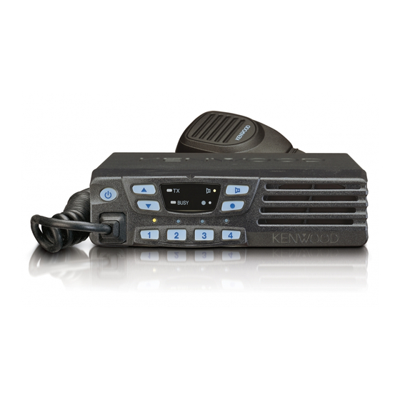
TK-7102H OPERATING FEATURES 1-3. Auxiliary Programmable Functions 1. Controls and Functions • Emergency • Scan On/OFF 1-1. Front Panel • Key Lock • Talk Around • Monitor • Temporary Delete • None (no function) • AUX • Horn Alert • Scan + Temporary Delete 1-4. - Page 5 • Key lock 2. Operation Features Pressing this key causes the transceiver to accept entry of The TK-7102H is a VHF FM radio designed to operate in only the [Vol Up/Down]*, [Key lock], Microphone [PTT], conventional format. The programmable features are sum- [Monitor], [Emergency], and [Power] keys.
- Page 6 TK-7102H OPERATING FEATURES ■ PTT ID 4. Scan Operating PTT ID provides a DTMF ANI or MSK ID to be sent with ■ SCAN start condition every time PTT (connect ID at beginning of transmission, dis- Two or more channels must be added to all channels that connect ID at end of transmission, or both).
-
Page 7: Audible User Feedback Tones
TK-7102H OPERATING FEATURES ■ SP Unmute 7. Audible User Feedback Tones You can select the type of SP Unmute system for each The transceiver outputs various combinations of tones to channel. The selection is as follows. notify the user of the transceiver operating state. -
Page 8: Realignment
TK-7102H REALIGNMENT 3-2. Connection Procedure 1. Modes 1. Connect the TK-7102H to the personal computer with the interface cable. User mode 2. When the Power is switched on, user mode can be en- tered immediately. When the PC sends a command, the... -
Page 9: Clone Mode
) from the chassis. Peel the Clone mode should enabled. pad as shown in Figure 3 ( 1. Turn the master TK-7102H power ON with the [1] key held down. The TK-7102H [●] LED is turned on. 2. Power on the slave TK-7102H. - Page 10 TK-7102H REALIGNMENT ■ Accessory Port Function 3. Insert the KCT-39 cable ( ) into the chassis ( ). The wire harness band ( ) must be inside the chassis and Color Internal Name face down. 4. Connect the KCT-39 to the TX-RX unit as shown in Figure...
-
Page 11: Installation
TK-7102H REALIGNMENT / INSTALLATION 6-3. Modifying the Transceiver INSTALLATION Modify the transceiver as follows to turn the power on and off with the ignition key. 1. Optional Board 1. Remove the jumper resistor (0Ω) R71 of the TX-RX unit. 1-1. Voice Scrambler Board Connection ■... - Page 12 TK-7102H INSTALLATION ■ Pins Connection 1-2. Example for Connection ■ Picture (Trunking Board) Voice scrambler 12 pins lead wire 11 pins lead wire functions with connector (A) with connector (B) A-12 – A-11 – A-10 – – – – –...
-
Page 13: Disassembly For Repair
TK-7102H DISASSEMBLY FOR REPAIR 1. When you remove the panel, turn the transceiver up side 4. Mount the display unit down. Detach the panel by lifting the tabs as shown be- To mount the display unit on the panel, follow the correct procedures shown to ensure easy display unit assembly low. -
Page 14: Circuit Description
TK-7102H CIRCUIT DESCRIPTION ■ IF Amplifier Frequency Configuration The first IF signal is amplified by Q351, and the enters The receiver utilizes double conversion. The first IF is IC301 (FM processing IC). The signal is heterodyned again 49.95MHz and the second IF is 450kHz. The first local oscil- with a second local oscillator signal within IC301 to create a lator signal is supplied from the PLL circuit. - Page 15 TK-7102H CIRCUIT DESCRIPTION ■ Wide/Narrow Changeover Circuit ■ Squelch Circuit The Wide port (pin 65) and Narrow port (pin 64) of the CPU The detection output from the FM IF IC (IC301) passes is used to switch between ceramic filters. When the Wide through a noise amplifier (Q301) to detect noise.
- Page 16 TK-7102H CIRCUIT DESCRIPTION ■ Unlock Circuit Transmitter System During reception, the 8RC signal goes high, the 8TC signal ■ Outline goes low, and Q34 turns on. Q33 turns on and a voltage is The transmitter circuit produces and amplifies the desired applied to the collector (8R).
- Page 17 CIRCUIT DESCRIPTION ■ Key Matrix Circuit Control Circuit The TK-7102H front panel has function keys. Each of The CPU carries out the following tasks: them is connected to a cross point of a matrix of the KMI1 to 1) Controls the WIDE, NARROW, TX/RX outputs.
-
Page 18: Semiconductor Data
TK-7102H CIRCUIT DESCRIPTION / SEMICONDUCTOR DATA ■ Decode • QT/DQT/DTMF The signal (W/NO (EVOL2)) goes to SIGNAL (pin 88) of CPU (IC101). The QT/DQT signal will pass through the low- pass filters in the CPU (IC101) and be decoded within the CPU (IC101). - Page 19 TK-7102H SEMICONDUCTOR DATA Microprocessor : 30622MAA-B83GP (TX-RX Unit IC101) ■ Terminal Function Pin No. Name Function Pin No. Name Function QT/DQT QT/DQT output. AMPSW AF AMP switch. DTMF/MSK DTMF/MSK/BEEP output Common data. PLLE PLL IC chip select. Common clock. 55,56 GND.
-
Page 20: Components Description
TK-7102H COMPONENTS DESCRIPTION Display Unit (X54-3460-20) Ref. No. Parts name Description Ref. No. Parts name Description Q254 Digital transistor AF mute / Active while SPM is H Shift register for LED & MICBL control Q255 Transistor AF mute / Active while AMPSW is H... -
Page 21: Parts List
TK-7102H PARTS LIST ✽ New Parts. indicates safety critical components. L : Scandinavia K : USA P : Canada Parts without Parts No. are not supplied. Y : PX (Far East, Hawaii) T : England E : Europe Les articles non mentionnes dans le Parts No. ne sont pas fournis. - Page 22 TK-7102H PARTS LIST TX-RX UNIT (X57-6700-XX) Desti- Desti- Ref. No. Address Parts No. Description Ref. No. Address Parts No. Description parts nation parts nation C103 CK73GB1H102K CHIP C 1000PF C301 C92-0507-05 CHIP-TAN 4.7UF 6.3WV C104 CK73GB1C104K CHIP C 0.10UF C302...
- Page 23 TK-7102H PARTS LIST TX-RX UNIT (X57-6700-XX) Desti- Desti- Ref. No. Address Parts No. Description Ref. No. Address Parts No. Description parts nation parts nation C416-418 CK73GB1H102K CHIP C 1000PF C526 CK73GB1H681K CHIP C 680PF C421,422 CK73GB1H471K CHIP C 470PF C527...
- Page 24 TK-7102H PARTS LIST TX-RX UNIT (X57-6700-XX) Desti- Desti- Ref. No. Address Parts No. Description Ref. No. Address Parts No. Description parts nation parts nation L352 L41-5685-08 SMALL FIXED INDUCTOR RK73GB1J473J CHIP R 1/16W L354-356 L34-4612-05 AIR-CORE COIL RK73GB1J472J CHIP R 4.7K...
- Page 25 TK-7102H PARTS LIST TX-RX UNIT (X57-6700-XX) Desti- Desti- Ref. No. Address Parts No. Description Ref. No. Address Parts No. Description parts nation parts nation R230 RK73GB1J124J CHIP R 120K 1/16W R355,356 RK73GB1J102J CHIP R 1.0K 1/16W K2,M2 R231 RK73GB1J683J CHIP R...
- Page 26 TK-7102H PARTS LIST TX-RX UNIT (X57-6700-XX) Desti- Desti- Ref. No. Address Parts No. Description Ref. No. Address Parts No. Description parts nation parts nation R440-442 RK73GB1J101J CHIP R 1/16W D604,605 XB15A709 DIODE K2,M2 R443 RK73GB1J222J CHIP R 2.2K 1/16W D605...
-
Page 27: Exploded View
TK-7102H EXPLODED VIEW A M2.6 x 8 : N67-2608-46 B M2.6 x 6 (Br-Tap) : N87-2606-46 C M2.6 x 14 (Br-Tap) : N87-2614-46 Bx12 Q504 IC252 Display unit TX-RX unit S/No. label Caution label Parts with the exploded numbers larger than 700 are not supplied. -
Page 28: Packing
TK-7102H PACKING 8 Instruction manual (English) (B62-1596-10) 37 Protection bag 703 Pamphlet (H25-2341-04) 702 Pamphlet 9 Instruction manual (Spanish) (B62-1597-10) 37 Protection bag (H25-2341-04) 35 Packing fixture (H12-3112-05) 35 Packing fixture (H12-3112-05) 48 Microphone (T91-0624-05) : K,K2 38 Item carton cse... -
Page 29: Adjustment
TK-7102H ADJUSTMENT Test Equipment Required for Alignment Test Equipment Major Specifications 1. Standard Signal Generator Frequency Range 136 to 175MHz (SSG) Modulation Frequency modulation and external modulation Output –127dBm/0.1µV to greater than –7dBm/100mV 2. Power Meter Input Impedance 50Ω Operation Frequency... - Page 30 TK-7102H ADJUSTMENT ■ Notes Adjustment Location • EEPROM ■ Switch The tuning data (Deviation, Squelch, etc.) for the EEP- ROM, is stored in memory. When parts are changed, re- Power Display adjust the transceiver. Volume up/down Speaker • AF PA IC (IC252) How to mounting the IC252.
- Page 31 TK-7102H ADJUSTMENT Test Frequency (MHz) K2,M2 Channel 1 : Center 160.100 160.050 149.100 149.050 2 : Low 146.100 146.050 136.100 136.050 3 : High 173.900 173.950 161.900 161.950 160.000 160.000 149.000 149.000 160.200 160.200 149.200 149.200 160.400 160.400 149.400 149.400...
- Page 32 TK-7102H ADJUSTMENT Receiver Section Measurement Adjustment Specifications/ Item Condition Test equipment Terminal Parts Method Remarks 1. Seisitivity 1) CH : RX low (Wide/Narrow) Check SINAD CH : RX center (Wide/Narrow) Oscilloscope EXT. SP : 12dB or higher CH : RX high (Wide/Narrow) AF V.M...
- Page 33 TK-7102H ADJUSTMENT Measurement Adjustment Specifications/ Item Condition Test equipment Terminal Parts Method Remarks 5. DQT 1) CH : TX low (Wide) Modulation analyzer ANT PC key Adjust the waveform as below balance CH : TC center (Wide/Narrow) or Linear detector...
-
Page 34: Terminal Function
TK-7102H TERMINAL FUNCTION Name Function Name Function Battery voltage DC supply Ignition sens input DATAI External transmit signal input Ground DETO FM detector output TXAFI TX audio input from scrambler board FNC1 Programable I/O (programmed by FPU) TXAFO TX audio output to scrambler board... -
Page 35: Pc Board
TK-7102H PC BOARD DISPLAY UNIT (X54-3460-20) Component side view (J72-0916-09) J72-0916-09 Ref. No. Address MONI POWER DOWN PROG POWER HOOK KMI2 KMI1 KMI3 KMO1 KMI4 KMO2 HOOK DISPLAY UNIT (X54-3460-20) Foil side view (J72-0916-09) Ref. No. Address HOOK KMO2 KMI4... -
Page 36: Tx-Rx Unit (X57-6700-Xx)
TK-7102H PC BOARD TX-RX UNIT (X57-6700-XX) -22 : M -23 : M2 -24 : K -25 : K2 Component side view (J72-0886-19) Ref. No. Address IC33 IC161 IC201 IC202 IC203 C574 C527 C615 IC252 C576 C528 IC401 IC501 C546 C613... - Page 37 TK-7102H PC BOARD Ref. No. Address IC31 TX-RX UNIT (X57-6700-XX) -22 : M -23 : M2 -24 : K -25 : K2 Foil side view (J72-0886-19) IC32 IC34 IC35 IC66 IC101 IC251 CN601 IC301 IC402 L605 C616 C610 R601 D607...
- Page 38 TK-7102H PC BOARD Ref. No. Address Ref. No. Address TX-RX UNIT (X57-6700-XX) -22 : M -23 : M2 -24 : K -25 : K2 Component side view + Foil side (J72-0886-19) IC31 Q411 12L IC32 Q440 12J IC33 Q501 IC34...
-
Page 39: Schematic Diagram
TK-7102H Note : The components marked with a dot ( • ) are parts of layer 1. SCHEMATIC DIAGRAM X57-6700-XX TX-RX UNIT X54-3460-20 DISPLAY UNIT CN601 T:4.8V F501 RX VCO RF SWITCH Q501 PRE DRIVE AMP T:1.5V Q502 PRE DRIVE AMP... -
Page 40: Block Diagram
TK-7102H TK-7102H BLOCK DIAGRAM DISPLAY UNIT (X54-3460-20) TX-RX UNIT (X57-670x-xx) Q404 D602 2SC4649(N,P) MA4PH633 POWER Q502 Q503 Q504 Q405 Q410 IC402 Q411 Q501 D603~605 MICBL 2SC3357 PD55003 RD70HVF1 2SC5108(Y) XB15A709 FNC1~FNC8 2SK508NV(K52) UPB1509GV 2SC4649(N,P) 2SC3357 Q402 IC401 DRIVE FINAL PTT(TXD) -
Page 41: Level Diagram
TK-7102H TK-7102H LEVEL DIAGRAM Receiver Section Center Frequency 49.95MHz 450kHz Audio Frequency W : –77.5dBm W : –85.0dBm N : –74.0dBm N : –84.5dBm W : –123.5dBm W : –119.0dBm W : –104.5dBm W : –104.0dBm W : –112.0dBm W : –92.0dBm N : –123.0dBm... -
Page 42: Specification
TK-7102H SPECIFICATIONS GENERAL Frequency Range ....... K,M : 146 to 174MHz K2,M2 : 136 to 162MHz Channels / Groups ......4 channels Channel Spacing ......... Wide : 25kHz Narrow : 12.5kHz PLL Channel Stepping ......2.5, 5, 6.25, 7.5kHz Operating Voltage ....... 13.6V DC ± 15% Current Drain ........ - Page 43 Leuvensesteenweg 248 J, 1800 Vilvoorde, Belgium KENWOOD ELECTRONICS FRANCE S.A. 13, Boulevard Ney, 75018 Paris, France KENWOOD ELECTRONICS U.K. LIMITED KENWOOD House, Dwight Road, Watford, Herts., WD18 9EB United Kingdom KENWOOD ELECTRONICS EUROPE B.V. Amsterdamseweg 37, 1422 AC Uithoorn, The Netherlands KENWOOD ELECTRONICS ITALIA S.p.A.
Need help?
Do you have a question about the TK-7102H and is the answer not in the manual?
Questions and answers