Table of Contents
Advertisement
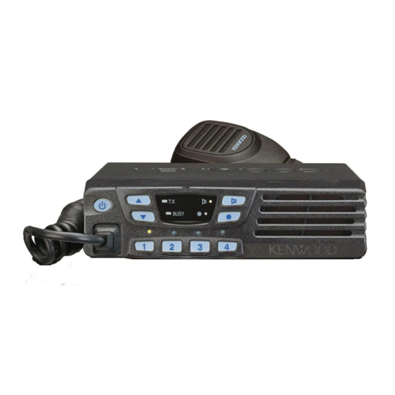
VHF FM TRANSCEIVER / VHF
TK-7108
SERVICE MANUAL /
REVISED /
This service manual applies to products with 50800001 or
subsequent serial numbers.
In terms of the products with the serial numbers earlier
than 50800001, refer to the TK-7108 service manual as per
part No. B51-8592-00 or B51-8636-00.
Cabinet
(A01-2178-02)
Modular jack
(E08-0877-05)
General .................................................. 2
System Set-Up ...................................... 5
OPERATING FEATURES .......................... 6
Realignment ....................................... 13
Installation ....................................... 19
Disassembly For Repair ................. 23
Circuit Description .......................... 24
Semiconductor Data ...................... 32
Components Description .............. 34
Parts List ............................................. 36
Exploded View .................................... 42
MM _RNJUSPSJMM qhJTNMU
Front glass
(B10-2753-03)
Key top
(K29-9065-01)
CONTENTS
PACKING ................................................. 43
Adjustment ........................................ 45
Terminal Function ........................... 52
PC BOARD
Display Unit (X54-3460-20) ............ 54
Tx-Rx Unit (X57-6913-01) ................ 56
Schematic Diagram .......................... 60
Block Diagram ................................... 64
Level Diagram .................................... 66
SPECIFICATION ...................................... 68
!
© 2003-11 PRINTED IN JAPAN
B51-8592-10 ( N ) 621
!"#$%RMUMMMMN
!"#$%&
!"#$% &'()"*=_RNJURVOJ
RMUMMMMN=
!"
Panel assy
(A62-0942-03)
Advertisement
Table of Contents

Subscribe to Our Youtube Channel
Related Manuals for Kenwood TK-7108


Summary of Contents for Kenwood TK-7108
- Page 1 !"#$% &'()"*=_RNJURVOJ subsequent serial numbers. RMUMMMMN= !" In terms of the products with the serial numbers earlier MM _RNJUSPSJMM qhJTNMU than 50800001, refer to the TK-7108 service manual as per part No. B51-8592-00 or B51-8636-00. Cabinet Front glass Panel assy (A01-2178-02)
-
Page 2: General
TK-7108 KKKKKKKKKKKKKKKKKKKKKKKKKKKKKKKKKKKKKKKKKKKKKKKKKKKKKKKKKKKKKKKKKKKKKKK O KKKKKKKKKKKKKKKKKKKKKKKKKKKKKKKKKKKKKKKKKKKKKKKKKKKKKKKKKKKKKKKKKKKK QP KKKKKKKKKKKKKKKKKKKKKKKKKKKKKKKKKKKKKKKKKKKKKKKKKKKKKKKKKKKKKKKKKKKKKKK R KKKKKKKKKKKKKKKKKKKKKKKKKKKKKKKKKKKKKKKKKKKKKKKKKKKKKKKKKKKKKKKKKKKK QS ! KKKKKKKKKKKKKKKKKKKKKKKKKKKKKKKKKKKKKKKKKKKKKKKKKKKKKKKKKKKKKKKKKKKKKKK S ! KKKKKKKKKKKKKKKKKKKKKKKKKKKKKKKKKKKKKKKKKKKKKKKKKKKKKKKKKKKKKKKKKKKK RP ! KKKKKKKKKKKKKKKKKKKKKKKKKKKKKKKKKKKKKKKKKKKKKKKKKKKKKKKKKKKKKKKKKKKKK NP ==== KKKKKKKKKKKKKKKKKKKKKKKKKKKKKKKKKKKKKKKKKKKKKKKKKKKKKKKKKKKKKKKKKKKKKKKK NV ==afpmi^v=rkfq=EuRQJPQSMJOMF KKKKKKKKKKKKKKKK RQ !"#$ KKKKKKKKKKKKKKKKKKKKKKKKKKKKKKKKKKKKKKKKKKKKKKKKKKKKKK OP ==quJou=rkfq=EuRTJSVNPJMNF KKKKKKKKKKKKKKKKKKKKKKK RS ! KKKKKKKKKKKKKKKKKKKKKKKKKKKKKKKKKKKKKKKKKKKKKKKKKKKKKKKKKKKKKKKKKKKK OQ KKKKKKKKKKKKKKKKKKKKKKKKKKKKKKKKKKKKKKKKKKKKKKKKKKKKKKKKKKKKKKKKKKKK SM !" KKKKKKKKKKKKKKKKKKKKKKKKKKKKKKKKKKKKKKKKKKKKKKKKKKKKKKKKKKKKKKKK PP KKKKKKKKKKKKKKKKKKKKKKKKKKKKKKKKKKKKKKKKKKKKKKKKKKKKKKKKKKKKKKKKKKKK SQ... - Page 3 TK-7108 GENERAL / !"#$% &'()*+, -./0123() • DO NOT transmit until all RF connectors are secure and !"#$%&'()*+,-./01 any open connectors are properly terminated. !"#$ %&'()*+,- ./01 2- 345 • SHUT OFF this equipment when near electrical blasting !" caps or while in an explosive atmosphere.
- Page 4 Control station. The antenna system selection depends on !"#$%&'()*+,%&-./ many factors and is beyond the scope of this manual. Your hbktlla !"#$ KENWOOD dealer can help you select an antenna system that will best serve your particular needs. !" 5-2. Radio location RJOK= !"#$%&'()*+,-.!/01 2/034...
-
Page 5: System Set-Up
TK-7108 SYSTEM SET-UP / Merchandise received Frequency range (MHz) RF power Type Choose the type of transceiver 146~174 See page 13. Transceiver programming A personal computer (IBM PC or compatible), programming interface (KPG-46), and programming software (KPG-70D) are required for programming. - Page 6 TK-7108 !"#$ NJPK= !" !" lkLlcc NJNK= !" !" !" !"#$% NJQK= NJOK= !"# !"#$%&'()*+,- !"#$%&'()*+,- !"#$%&'()*+,- !"#$%&'(=EN Q R NJRK= q =E !"#$%&'()*+ ,-./012N= !"#$%&' w ▲ !"#$%&' e ▼ !"#$%&' 天线连接器 外部扬声器插孔 r ● !"F= !"#$%&=E mc=E !"#$%&'()* !"F=...
-
Page 7: Operating Features
TK-7108 OPERATING FEATURES / 2. Operation Features !"#$%&'()*+,-./sec=cj The TK-7108 is a VHF FM radio designed to operate in con- qhJTNMU !"#$%&'()*+,# ventional format. The programmable features are summa- rized. !"#$%& 3. Transceiver Controls and Indicators !" 3-1. Front Panel Controls PJNK= !"#$%&'()*+%&,-.%&"/01... - Page 8 TK-7108 OPERATING FEATURES / • Key lock !"#$%&'=x Pressing this key causes the transceiver to accept entry of L zG =x !z= =x !"# only the [Vol Up/Down]*, [Key lock], Microphone [PTT], z =x z =x [Monitor], [Emergency], and [Power] keys.
- Page 9 TK-7108 OPERATING FEATURES / 4. Scan Operating ■ SCAN start condition !"#$ !"#$%&'()*+,-.!"/012$%3 Two or more channels must be added to all channels that !"#$=Emqq can be scanned. The transceiver must be in normal receive !"lkLlcc= !"#$%& ' ()*+,- mode (PTT off).
- Page 10 TK-7108 OPERATING FEATURES / ■ PTT ID mqq=fa !"#$%mqq !aqjc=^kf jph=fa PTT ID provides a DTMF ANI or MSK ID to be sent with mqq=fa !"#$ÅçååÉÅí=fa !"#$%ÇáëÅçååÉÅí every time PTT (connect ID at beginning of transmission, dis- !"#F connect ID at end of transmission, or both).
- Page 11 TK-7108 OPERATING FEATURES / ■ SP Unmute !"# !"#$%&'()*+,-./01 You can select the type of SP Unmute system for each channel. The selection is as follows. nqLanq !"#$%&'()*+,-./01fa Carrier, QT/DQT: Channel with this option will not check ID Code in order to aqjc nqLanq aqjc !"#$%&'()*+,-./01fa...
- Page 12 TK-7108 OPERATING FEATURES / !"#$ 7. Audible User Feedback Tones !"#$%&'(%&)* +,-./0 The transceiver outputs various combinations of tones to !" #$%&'( )*+hmdJTMa !"#$ notify the user of the transceiver operating state. Refer to the help file on the KPG-70D, regarding the func- tions that are not listed below.
-
Page 13: Realignment
Clone mode [1]+Power ON (Two seconds) !" 3. PC Mode 3-1. Preface PJNK= !"#$ % &'()=EhmdJQSF= !" The TK-7108 transceiver is programmed using a personal qhJTNMU !" computer, a programming interface (KPG-46) and program- EhmdJTMaF= !"# $%&'()*+,-N ming software (KPG-70D). !"# The programming software can be used with an IBM PC or compatible. - Page 14 !qhJTNMU ! qhJTNMU =x●z= !" Clone mode should enabled. =xNz= !qhJTNMU 1. Turn the master TK-7108 power ON with the [1] key held !"#$=EkçKbPMJPPUOJMRF= !"#$%"& down. The TK-7108 [●] LED is turned on. !"# 2. Power on the slave TK-7108.
- Page 15 TK-7108 REALIGNMENT / !"# 4-1. Adding the data password QJNK= !"#$%&'()*+,- . /01234567 If the data password is set in the optional feature menu, !"=E you must enter the password (Master transceiver) to activate !"#$%N O P Q !"#$%&NM a clone mode.
- Page 16 TK-7108 REALIGNMENT / 3. Attach a new cushion (G13-1960-08) to the DC bush. 6. Twist the large grouping of wires of the KCT-39 cable twice, then connect it to Terminal A of the PCB. !"#=EdNPJNVSMJMUF= Connect the remaining grouping of wires of the KCT-39 cable to Terminal B.
- Page 17 TK-7108 REALIGNMENT / 8. Align all cable to the left side so as to avoid the Power 10. Connect the KCT-39 to the external accessory by insert- Module Area. Mount the shielding cover and secure it ing the crimp terminal (...
- Page 18 TK-7108 REALIGNMENT / !"#$=Eh`qJNUF 6. Ignition Sense Cable (KCT-18) !"#$%&'()*!"#$+,-./ The KCT-18 is an optional cable for enabling the ignition h`qJNU !"#$%&'()*+,-./0 function. The ignition function lets you turn the power to the transceiver on and off with the car ignition key.
-
Page 19: Installation
TK-7108 INSTALLATION / 1. Optional Board !"#$%& 1-1. Voice Scrambler Board Connection NJNK= ■ Modification !"#$!%&'()* 1. Remove the cabinet and shielding cover from the trans- !oOMO oOST ceiver. quJou 2. Delete R202 and R267 on the TX-RX unit. TX-RX UNIT... - Page 20 TK-7108 INSTALLATION / ■ Pins Connection !" !" Voice scrambler 12 pins lead wire 11 pins lead wire functions with connector (A) with connector (B) A-12 – ^JNO A-11 – ^JNN A-10 – ^JNM – – – – – –...
- Page 21 TK-7108 INSTALLATION / 4. Connect the cable (E37-1117-05) to the topside of the ST- 2. SmarTrunk 909. 1. Unscrew the five M2.6 screws (N87-2614-46), then re- move the shielding cover (F10-2491-03). =EbPTJNNNTJMRF= pqJVMV Cable / 电缆 Connect point / 连接点 ST-909 !"#$%&=EcNMJ...
- Page 22 • ST-909 and ST-865KW4 are available from SmarTrunk sheet are included in the package. Systems,Inc. • For TK-7108 & TK-8108 series, cushion A is not used. Cushion A is replaced by cushion F. ■ Setting With the KPG-70D • Cushion B is replaced by cushion E.
-
Page 23: Disassembly For Repair
TK-7108 !"#$ DISASSEMBLY FOR REPAIR / 1. When you remove the panel, turn the transceiver up side 4. Mount the display unit down. Detach the panel by lifting the tabs as shown be- To mount the display unit on the panel, follow the correct procedures shown to ensure easy display unit assembly low. -
Page 24: Circuit Description
TK-7108 CIRCUIT DESCRIPTION / Frequency Configuration !"#$%&'()*+,-./&0QVKVRjeò The receiver utilizes double conversion. The first IF is !QRMâeò !"#$%&'()*+,-. 49.95MHz and the second IF is 450kHz. The first local oscil- !"#$%&'()*+,-./012N lator signal is supplied from the PLL circuit. The PLL circuit in the transmitter generates the necessary frequencies. - Page 25 TK-7108 CIRCUIT DESCRIPTION / ■ IF Amplifier !"# !"#$%nPRN ! "#$%f`PMN=E !" The first IF signal is amplified by Q351, and the enters !"#f`PMN !"#$%&'()*QRMâeò IC301 (FM processing IC). The signal is heterodyned again !"#$ !"%&'()*+,QRMâeò with a second local oscillator signal within IC301 to create a !"#$%&'()*...
- Page 26 TK-7108 CIRCUIT DESCRIPTION / ■ Wide/Narrow Switching Circuit !"#$% !"#$ The Wide port (pin 65) and Narrow port (pin 64) of the CPU SRF= SQF= !"#$%&'()*+,- ./012p t is used to switch between ceramic filters. When the Wide !"#$%&' port is high, the ceramic filter SW diodes (D303, D302) cause EaPMP aPMOF= `cPMN !"#$%&' ()*+,pt...
- Page 27 TK-7108 CIRCUIT DESCRIPTION / !"#$% PLL Frequency Synthesizer !"#$%&'()*+,-./0123(345 The PLL circuit generates the first local oscillator signal for reception and the RF signal for transmission. ■ PLL !"# !"#$%&'(R SKORâeò NSKUjeò !" The frequency step of the PLL circuit is 5 or 6.25kHz. A !"#$%&'(...
- Page 28 TK-7108 CIRCUIT DESCRIPTION / !" Transmitter System ■ Outline !"#$%&'()*+,-./0123456, The transmitter circuit produces and amplifies the desired !"#$%&'()*+ frequency directly. It FM-modulates the carrier signal by means of a varicap diode. ■ Power Amplifier Circuit !"#$% !"#$%&'()*+,'(L !"#$ The transmit output signal from the VCO passes through !"#$= EnRMN...
- Page 29 TK-7108 CIRCUIT DESCRIPTION / Control Circuit !"#$ The CPU carries out the following tasks: ! "! #$=L !" 1) Controls the WIDE, NARROW, TX/RX outputs. !"#$%&'()* 2) Adjusts the AF signal level of the AF filter (IC251) and =Ef`ORNF= ^c !"#...
- Page 30 TK-7108 CIRCUIT DESCRIPTION / ■ Key Matrix Circuit !"#$ !"#$%&'()*+&,-./012 The TK-7102 front panel has function keys. Each of them qhJTNMU !"#$%&'()hjfN hjfQ is connected to a cross point of a matrix of the KMI1 to KMO2 hjfN hjlO !"#$%& hjlN hjlO !"#$%&...
- Page 31 TK-7108 CIRCUIT DESCRIPTION / ■ D/A Converter !=Ef`PF= The D/A converter (IC161) is used to adjust MO modula- !m`=mltbo=`lkqoli tion, AF volume, TV voltage, FC reference voltage, and PC !"#$%&!'(!)*+,-./012 POWER CONTROL voltage level. !"#$%&'( Adjustment values are sent from the CPU as serial data.
-
Page 32: Semiconductor Data
TK-7108 SEMICONDUCTOR DATA Microprocessor : 30622MAA-B87GP (TX-RX Unit IC101) ■ Terminal Function Pin No. Name Function Pin No. Name Function QT/DQT QT/DQT output. AMPSW AF AMP switch. DTMF/MSK DTMF/MSK/BEEP output Common data. PLLE PLL IC chip select. Common clock. 55,56 GND. - Page 33 TK-7108 !" !"PMSOOj^^J_UTdm=EquJou f`NMNF !"# nqLanq nqLanq ^jmpt aqjcLjph aqjcLjphL_bbm miib RR RS RTúRV apqN apqP `kspp `ksëë bsiia _pefcq obpbq ulrq u í~ä=ENQKPNUjeòF k^oolt tfab u í~ä=ENQKPNUjeòF SS SU k` !"i`a !" mltbo µ`lj jf`jqN jf`bj quLou jf`jqO ! "# OO OR k` !"...
-
Page 34: Components Description
TK-7108 COMPONENTS DESCRIPTION Display Unit (X54-3460-20) Ref. No. Parts name Description Ref. No. Parts name Description Q251 Transistor Buffer amplifier / RX audio Shift register for LED & MICBL control Q252,253 FET AF mute / Active while AFM is H... - Page 35 TK-7108 !=EuRQJPQSMJOMF !" nORO ORP L ^cj e !"#$% !" iba=C=jf`_i nORQ L pmj e !"! nORR L ^jmpt e !"#$% !"Lpni nV NM nPMN !" !"# !"LNSKUjeò !"#$ aN Q nPMO !" !" !" nPRN !" !"# !" nPRO !"...
-
Page 36: Parts List
Les articles non mentionnes dans le Parts No. ne sont pas fournis. Y : AAFES (Europe) X : Australia M : Other Areas Teile ohne Parts No. werden nicht geliefert. TK-7108, DISPLAY UNIT (X54-3460-20) TX-RX UNIT (X57-6913-01) Desti- Desti- Ref. No. - Page 37 TK-7108 PARTS LIST / TX-RX UNIT (X57-6913-01) Desti- Desti- Ref. No. Address Parts No. Description Ref. No. Address Parts No. Description parts nation parts nation C162 C92-0507-05 CHIP-TAN 4.7UF 6.3WV C307 CK73GB1E223K CHIP C 0.022UF C163 CK73GB1H102K CHIP C 1000PF...
- Page 38 TK-7108 PARTS LIST / TX-RX UNIT (X57-6913-01) Desti- Desti- Ref. No. Address Parts No. Description Ref. No. Address Parts No. Description parts nation parts nation C432 CC73GCH1H0R5B CHIP C 0.5PF C612 C93-0557-05 CHIP C 7.0PF C434 CK73GB1H471K CHIP C 470PF...
- Page 39 TK-7108 PARTS LIST / TX-RX UNIT (X57-6913-01) Desti- Desti- Ref. No. Address Parts No. Description Ref. No. Address Parts No. Description parts nation parts nation RK73GB1J152J CHIP R 1.5K 1/16W R218 RK73GB1J823J CHIP R 1/16W R92-1252-05 CHIP R 0 OHM J...
- Page 40 TK-7108 PARTS LIST / TX-RX UNIT (X57-6913-01) Desti- Desti- Ref. No. Address Parts No. Description Ref. No. Address Parts No. Description parts nation parts nation R322 RK73GB1J101J CHIP R 1/16W R437 RK73GB1J102J CHIP R 1.0K 1/16W R323 RK73GB1J224J CHIP R...
- Page 41 TK-7108 PARTS LIST / TX-RX UNIT (X57-6913-01) Desti- Desti- Ref. No. Address Parts No. Description Ref. No. Address Parts No. Description parts nation parts nation D603 XB15A709 DIODE D606,607 MA742 DIODE D608,609 1SS355 DIODE IC31 KIA7808AF ANALOG IC IC32,33 NJM78L05UA...
-
Page 42: Exploded View
TK-7108 !" EXPLODED VIEW / A M3 x 8 : N67-3008-46 B M2.6 x 6 (Br-Tap) : N87-2606-46 C M2.6 x 14 (Br-Tap) : N87-2614-46 Part name label face down Display unit IC502 IC252 TX-RX unit S/No. label Parts with the exploded numbers larger than 700 are not supplied. -
Page 43: Packing
TK-7108 PACKING (M TYPE) / 50 Screw set 46 Bracket (N99-0395-05) (J29-0662-03) 41 Protection bag (H25-0103-04) 12 DC cord (E30-3339-05) 23 Fuse (6*30) (F51-0016-05) x 2 38 Inner packing case (H02-0617-02) 7 Instruction manual (B62-1664-10) 39 Polystyrene foamed fixture (H10-6636-13) - Page 44 TK-7108 PACKING (C TYPE) / 7 Instruction manual (B62-1390-20) 39 Polystyrene foamed fixture (H10-6636-13) 42 Protection bag (H25-2320-04) 40 Polystyrene foamed fixture (H10-6639-03) 43 Item carton case (H52-1700-12) KMB-19 (Installation kit) Protection bag (H25-0103-04) DC cord (E30-3339-05) Screw set Bracket...
-
Page 45: Adjustment
TK-7108 ADJUSTMENT Test Equipment Required for Alignment Test Equipment Major Specifications 1. Standard Signal Generator Frequency Range 136 to 175MHz (SSG) Modulation Frequency modulation and external modulation Output –127dBm/0.1µV to greater than –7dBm/100mV 2. Power Meter Input Impedance 50Ω Operation Frequency... - Page 46 TK-7108 !"#$ %&'( !"#$=EppdF NPS NTRjeò !" # !TÇ_ãLNMMãs JNOTÇ_ãLMKNµs RMΩ NPR NTRjeò NMMt NPS NTRjeò !"=EasjF Ns OMs !"#$%&'()* PMjeò !"#$%& NMeò NMMMjeò !" MKOééã !"=E^c=sqsjF RMeò NMâeò Nãs Ps !"=E^dF OMeò OMâeò M Ns !" Nâeò P RMãs NMsêãë...
- Page 47 TK-7108 ADJUSTMENT / • AF PA IC (IC252) Adjustment Location / How to mounting the IC252. ■ Switch / !"#=Ef`OROF Power Display !" 电源 显示 f`ORO Volume up/down Speaker 音量高/低 扬声器 Pin 1 marker TX-RX unit Component side MIC jack 1/2/3/4 keys 话筒插座...
- Page 48 TK-7108 ADJUSTMENT PCB Section Measurement Adjustment Specifications/ Item Condition Remarks Test equipment Terminal Parts Method 1. Setting 1) Power supply voltage DC Power supply terminal : 13.6V ± 0.1V 2. VCO lock 1) CH : TX high Digital voltmeter TC402 5.5V...
- Page 49 TK-7108 !"#$NPKSs ! NF `e !" !" q`QMO RKRs MKNs !"# OF `e q`QMN RKRs MKNs !"# PF `e MKTs !"# QF `e !"=E F PK fc=Åçáä iPMN PKOR PKPRs=Ea`F !"#$%& !" JRPÇ_ã=ERMNµsF Nâeò Pâeò !"#=E F !" QK oc...
- Page 50 TK-7108 ADJUSTMENT Measurement Adjustment Specifications/ Item Condition Remarks Test equipment Terminal Parts Method 3. Squelch 1 1) CH : RX low (Wide) PC key Adjust to open the squelch CH : RX center (Wide/Narrow) CH : RX high (Wide) 2) SSG output : –120dBm (0.22µV) (Wide)
- Page 51 TK-7108 ! NF `e !"=E F !"#$ !"#=E L F !"=E F !"#$%& NOMÇ_ã=EMKOOµsF=E F NNVÇ_ã=EMKORµsF=E F Nâeò PKMâeò=E F NKRâeò=E F !"# !" !"# NF `e NMMeò ! NF `e !" eÉñ=Ç~í~=ORR !" NF `e NKMt !"# !"# !"# !"...
-
Page 52: Terminal Function
TK-7108 TERMINAL FUNCTION ■ Function Port Assignment Name Function KDS100, KGP-2A/2B Data Name Clock FNC1 Chip enable FNC2 FNC3 Data Channel Switched B FNC4 KMO2 Key matrix output 2 FNC5 Carrier Operated Relay KMI4 Key matrix input 4 FNC6 Audio Mute... - Page 53 TK-7108 !"#$ kçK hapNMMI=hdmJO^LO_ ck`N ck`O ck`P ck`Q !"# hjlO ck`R hjfQ ck`S !" hjlN ck`T hjfP ck`U hjfN pã~êqêìåâ=ff !"#$ hjfO ck`N ellh Loua ck`O ck`P mltbo ck`Q ck`R mqqLqua ck`S ck`T ck`U ck`N kçK ck`O ck`P ck`Q !"N=ENF ck`R !"...
- Page 54 TK-7108 板 PC BOARD / PC DISPLAY UNIT (X54-3460-20) Component side view (J72-0916-09) POWER DOWN DISPLAY UNIT (X54-3460-20) Foil side view (J72-0916-09) HOOK...
- Page 55 TK-7108 板 PC BOARD / PC DISPLAY UNIT (X54-3460-20) Component side view (J72-0916-09) J72-0916-09 Ref. No. Address MONI PROG Component side Layer 1 Layer 2 Foil side DISPLAY UNIT (X54-3460-20) Foil side view (J72-0916-09) Ref. No. Address KMO2 KMI4 KMO1...
- Page 56 TK-7108 TK-7108 板 板 PC BOARD / PC PC BOARD / PC DISPLAY UNIT (X54-3460-20) Component side view (J72-0916-09) DISPLAY UNIT (X54-3460-20) Component side view (J72-0916-09) J72-0916-09 Ref. No. Address MONI POWER DOWN PROG Component side Layer 1 Layer 2...
-
Page 57: Tx-Rx Unit (X57-6913-01)
TK-7108 板 PC BOARD / PC TX-RX UNIT (X57-6913-01) Component side view (J72-0917-09) EXT. SP R272 D251 C272 R274 R275 C271 R273 TEMP2 CNVSS IC252 R101 R271 C276 POWER C270 R270 RESET Q254 R267 R223 R202 R277 DETO2 R105 R151... - Page 58 TK-7108 板 PC BOARD / PC TX-RX UNIT (X57-6913-01) Component side view (J72-0917-09) IC502 C615 C610 R601 C612 TH98 C607 R603 D606 R602 R605 R533 R606 R532 TEMP1 R531 R379 C389 C518 C545 C516 C574 Q354 R221 R350 C220 R161...
- Page 59 TK-7108 TK-7108 板 板 PC BOARD / PC PC BOARD / PC TX-RX UNIT (X57-6913-01) TX-RX UNIT (X57-6913-01) Component side view (J72-0917-09) Component side view (J72-0917-09) EXT. SP IC502 C615 C610 R601 C612 TH98 C607 R603 D606 R602 R605 R533...
- Page 60 TK-7108 板 PC BOARD / PC TX-RX UNIT (X57-6913-01) Foil side view (J72-0917-09) R800 L604 C387 R376 C388 R378 D354 L601 L357 D603 L503 TC352 C576 C384 CN301 CN503 D352 C377 C370 R359 R370 R374 C367 C373 C368 Q353 R503...
- Page 61 TK-7108 板 PC BOARD / PC TX-RX UNIT (X57-6913-01) Foil side view (J72-0917-09) C283 R281 R520 R517 C524 R515 C515 CN502 CN501 C510 C509 L502 R513 R509 Q502 R103 R102 R512 C279 D502 R131 R130 C104 R129 C431 D404 L101...
- Page 62 TK-7108 TK-7108 板 板 PC BOARD / PC PC BOARD / PC TX-RX UNIT (X57-6913-01) TX-RX UNIT (X57-6913-01) Foil side view (J72-0917-09) Foil side view (J72-0917-09) C283 R281 R800 L604 C387 R376 C388 R378 D354 L601 L357 D603 TC352 L503...
-
Page 63: Schematic Diagram
TK-7108 SCHEMATIC DIAGRAM / TX-RX UNIT (X57-6913-01) D403,404 C430 RX VCO Q402,403 RX VCO R:6.5V R:0.8V CHARGE PUMP Q405 L406 C426 D404 L408 2SK508NV(K52) C432 R403 R414 R402 MA2S304 0.5p VOTAGE R401 DROPPED D402 R410 Q402 8.2k L405 HZU5ALL R418... - Page 64 TK-7108 SCHEMATIC DIAGRAM / TX-RX UNIT (X57-6913-01) T:6.7V PRE DRIVE AMP 6.2V BUFFER AMP RF AMP T:1.0V RF SWITCH T:1.2V 4.8V Q501 7.2V Q410 Q411 C502 C503 2SC3357 C509 1.2V R503 2SC5108(Y) 2SC4649(N,P) L421 C466 VCC1 VCC2 C456 C459 C460...
- Page 65 TK-7108 SCHEMATIC DIAGRAM / TX-RX UNIT (X57-6913-01) IC502 POWER MODULE DRIVE1 T:6.0V RA30H1317M-31 Q502 C515 2SC3357 R800 C516 C604 C612 T:0.6V R92-1061-05 ANT SW T:12.9V D602 L604 L503 MA4PH633 C603 L603 2.5T 1000p T:0.9V D502 DA221 D606,607 APC VOLTAGE D1-3...
- Page 66 TK-7108 SCHEMATIC DIAGRAM / DISPLAY UNIT (X54-3460-20) D1-4 Q9,10 KRA225S KEY BACKLIT KEY BACKLIT SWITCH 3.7V 13.46V 2.7k KRC102S B30-2238-05 B30-2238-05 NORMAL AMBER 3.7V 2.7k B30-2238-05 B30-2238-05 2.2k 4.23V MICBL MICBL HOOK HOOK MONITOR KEY LIGHT 0.17V 11.4V SHIFT REGISTER FOR 2.7k...
- Page 67 TX-RX UNIT (X57-6913-01) DISPLAY UNIT (X54-3460-20) T:6.7V IC502 PRE DRIVE AMP DRIVE1 T:6.0V POWER MODULE D403,404 BUFFER AMP 6.2V RF AMP RA30H1317M-31 RX VCO C430 4.8V RF SWITCH T:1.0V T:1.2V Q502 Q402,403 RX VCO 7.2V Q501 C515 R:6.5V R:0.8V Q410 1.2V Q411 C502...
-
Page 68: Block Diagram
TK-7108 BLOCK DIAGRAM / DISPLAY UNIT X54-3460-20 TX-RX UNIT X57-6913-01 Q404 2SC4649(N,P) POWER FNC1~FNC8 2SK508 Q402 IC401 PTT(TXD) CHARGE 2SA1832(GR) MB15A02 PUMP PLLE HOOK(RXD) LOOP Q407 DATAI PLL IC FILTER 2SJ243 DETO TXAFI 16.8MHz CHARGE Q403 TXAFO PUMP 16.8MHz 2SC4738(GR) - Page 69 TK-7108 BLOCK DIAGRAM / IC502 RA30H1317M-31 POWER MODULE Q411 Q501 Q502 Q405 IC402 2SC4649 Q410 D602 2SC3357 2SC3357 UPB1509GV (N,P) 2SK508NV(K52) 2SC5108(Y) MA4PH633 DRIVE DIVIDER BUFF DRIVE ANT SW Q408 Q407 D409 KRX102U 2SJ243 DAN235E POW. POW. D606 D607 Q302...
-
Page 70: Level Diagram
TK-7108 LEVEL DIAGRAM / Receiver Section / Center Frequency 49.95MHz 450kHz W : –77.5dBm N : –74.0dBm W : –123.5dBm W : –119.0dBm W : –104.5dBm W : –104.0dBm W : –112.0dBm W : –92.0dBm /CF2 N : –123.0dBm N : –118.5dBm N : –103.5dBm... - Page 71 TK-7108 LEVEL DIAGRAM / 450kHz Audio Frequency W : –85.0dBm N : –84.5dBm /CF2 0.33Vrms 0.32Vrms 0.26Vrms 0.30Vrms 0.31Vrms 10mVrms 0.50Vrms 0.45Vrms IC301 IC251 IC251 IC251 IC251 IC161 IC252 Q251 vel meter. 2dB SINAD.) To make measurements in the AF section, connect the AC level meter.
-
Page 72: Specification
TK-7108 SPECIFICATIONS GENERAL Frequency Range ........... C,M : 146 to 174MHz Number of Channels ........8 channels Channel Spacing ..........Wide : 25kHz Narrow : 12.5kHz PLL Channel Stepping ........2.5, 5, 6.25, 7.5kHz Operating Voltage ........... 13.6V DC ± 15% Current Drain .......... - Page 73 TK-7108 ! KKKKKKKKKKKKKKKKKKKKKKKKKKKKKKKKKKKKKKKKKKKKKKKKKKKKKKKKKKK NQS NTQjeò ! KKKKKKKKKKKKKKKKKKKKKKKKKKKKKKKKKKKKKKKKKKKKKKKKKKKKKKKKKKK U ! KKKKKKKKKKKKKKKKKKKKKKKKKKKKKKKKKKKKKKKKKKKKKKKKKKKKKKKKKKK ORâeò NOKRâeò !"#$%& KKKKKKKKKKKKKKKKKKKKKKKKKKKKKKKKKKKKKKKK OKR R SKOR TKRâeò ! KKKKKKKKKKKKKKKKKKKKKKKKKKKKKKKKKKKKKKKKKKKKKKKKKKKKKKKKKKK NPKSs ! KKKKKKKKKKKKKKKKKKKKKKKKKKKKKKKKKKKKKKKKKKKKKKKKKKKKKKKKKKK !"#MKQ^ !"#NKM^ !"#UKM^ !"# KKKKKKKKKKKKKKKKKKKKKKKKKKKKKKKKKKKKKKKKKKKKKKKKKKK !" KKKKKKKKKKKKKKKKKKKKKKKKKKKKKKKKKKKKKKKKKKKKKKKKKKKKKKK NSM=E F QP=E F NMT=E F= !NKMâÖ !"# KKKKKKKKKKKKKKKKKKKKKKKKKKKKKKKKKKKKKKKKKKKKKKKKKKK OUjeò...
- Page 74 Leuvensesteenweg 248 J, 1800 Vilvoorde, Belgium KENWOOD ELECTRONICS FRANCE S.A. 13, Boulevard Ney, 75018 Paris, France KENWOOD ELECTRONICS U.K. LIMITED KENWOOD House, Dwight Road, Watford, Herts., WD18 9EB United Kingdom KENWOOD ELECTRONICS EUROPE B.V. Amsterdamseweg 37, 1422 AC Uithoorn, The Netherlands KENWOOD ELECTRONICS ITALIA S.p.A.
Need help?
Do you have a question about the TK-7108 and is the answer not in the manual?
Questions and answers