Table of Contents
Advertisement
Advertisement
Table of Contents
Troubleshooting

Related Manuals for Agilent Technologies G1369C

Summary of Contents for Agilent Technologies G1369C
- Page 1 Agilent G1369C LAN Interface Card User Manual Agilent Technologies...
-
Page 2: Safety Notices
Software Revision Technology Licenses This guide is valid for A.01.xx revisions of the Agilent G1369C LAN Interface Card soft- The hardware and/or software described in WA R N I N G ware, where xx refers to minor revisions of... -
Page 3: In This Guide
In this chapter you will find instructions to help you to set- up your LAN Interface Card based on the Agilent 1100/1200/1260 series HPLC modules. Getting Help In this chapter you will find support information about troubleshooting, repair and the Agilent web. G1369C LAN Interface User Manual... - Page 4 G1369C LAN Interface User Manual...
-
Page 5: Table Of Contents
Configuring the CAG Bootp Server Program Storing the Settings Permanently with Bootp Program Manual Configuration With Telnet With Handheld Controller G1323B PC and Agilent ChemStation Setup PC Setup for Local Configuration Agilent ChemStation Setup Hosted Module Support Troubleshooting G1369C LAN Interface User Manual... - Page 6 Contents Link Status LEDs Error Messages Repair and Parts Information Firmware Update Update Procedure Agilent Support Information Reporting of Problems Agilent Web Glossary G1369C LAN Interface User Manual...
- Page 7 Agilent G1369C LAN Interface Card User Manual Introduction - Around your LAN Interface Card Introduction to the LAN Interface Card LAN Control - What Exactly Does It Do? LAN Interface Card - What Has To Be Done? LAN Control Configurations...
-
Page 8: Introduction To The Lan Interface Card
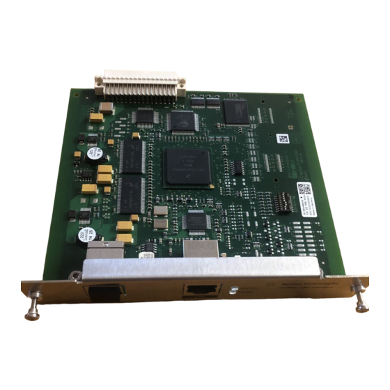
JetDirect card in the Agilent 1100/1200/1260 series HPLC modules, the 8453 UV- vis spectrophometer, the 35900E A/D converter and the 6850 Series GC. CAN port for “Hosted Module Support”, see page 51 LAN port control of the module/system Figure 1 LAN Interface Card G1369C LAN Interface User Manual... -
Page 9: Versions Of Lan Cards
• control of your instrument and acquires data “remotely” from your desktop (easier access), • a direct replacement for GP- IB (HP- IB) interface protocol, • allows your instrument to be placed anywhere on the laboratory/corporate network, • improves lab “ergonomics” (better organization), G1369C LAN Interface User Manual... -
Page 10: Lan Interface Card - What Has To Be Done
• install network interface card (NIC) into PC (if not already pre- installed or on- board). • connect to instrument • direct with cross- over cable or • to HUB with twisted pair cable • configure instrument on LAN G1369C LAN Interface User Manual... -
Page 11: Lan Control Configurations
LAN Using a HUB and Twisted Pair Cables More complicated setup than direct cross- over connection. Patch-cable Shielded Twisted pair 7 m (5023-0202) for all cables Figure 3 LAN configuration using a HUB and twisted pair cables G1369C LAN Interface User Manual... -
Page 12: Lan With Existing Customer Network
The customer LAN must be able to handle instrument data and must have sufficient bandwidth for instrument acquisition (no overnight backups over the LAN). Patch-cable Shielded 7 m (5023-0202) for all cables Figure 4 LAN configuration with existing customer network G1369C LAN Interface User Manual... -
Page 13: Lan Interface Card Compatibility
Agilent 8453 Spectrophotometer Firmware 3.30 Agilent 35900E A/D converter requires G1369A board revision Rev. C.03.00 (introduced 04/2005) or G1369B or G1369C Agilent 6850 Series GC requires G1369A board revision Rev. C.03.00 (introduced 04/2005) or G1369B or G1369C Agilent Control Module G1818A... - Page 14 G1311-66520 or higher G1311A below DE64301137, US64401134 G1311-66520 or higher G1312A below DE64300703, US64400425 G1312-66520 or higher G1313A below DE64302092, US64400886 G1313-66520 or higher G1314A below JP64201926 G1314-66521 or higher G1315A below DE64301532, US64400333 G1315-66520 or higher G1369C LAN Interface User Manual...
- Page 15 Agilent G1369C LAN Interface Card User Manual Getting Started Installing and Cabling the LAN Interface Card What You Will Get What You Have To Do First LAN Interface Card Configuration TCP/IP Parameter Configuration Configuration Switches Initialization Mode Selection Bootp Bootp & Store...
-
Page 16: Installing And Cabling The Lan Interface Card
G1369C (G1369-60012) - Packaging CAN cable 1 m Patch-cable (5181-1519) Twisted pair Shielded 7 m (5023-0202 Patch-cable CD-ROM with the Cross-over Shielded manual 3 m (5023-0203) Figure 5 What you will get (Content of G1369C/G1369-60012) G1369C LAN Interface User Manual... -
Page 17: What You Have To Do First
1 Remove the LAN Interface Card from it’s packaging. Configuration switch, “Configuration Switches” page 21 MAC label, see Figure 7 on page 18 Board information (manufacturing part number, revision) Figure 6 Board Layout G1369C G1369C LAN Interface User Manual... - Page 18 If the module has the 1100 CAN modification board installed, it probably has a revision 1 N O T E mainboard and will not accept the LAN interface. Refer to “LAN Interface Card Compatibility” on page 13 Figure 8 Location of LAN Interface Card (e.g. 1100/1200 series detector) G1369C LAN Interface User Manual...
- Page 19 LAN port control of the "hosted module" connect with the provided CAN cable to module/system a free CAN port on the LC system, see page Figure 9 Connect the LAN cable to the correct connector G1369C LAN Interface User Manual...
-
Page 20: Lan Interface Card Configuration
TCP/IP parameters after power- on. The parameters may be derived from a Bootp cycle, non- volatile memory or initialized with known default values. The initialization mode is selected by the configuration switch, see Figure 10 on page 21. G1369C LAN Interface User Manual... -
Page 21: Configuration Switches
27 Compared to the G1369A LAN Card, SW 7 and SW 8 must be always in OFF position on the N O T E G1369B/B LAN Card, otherwise the selected modes are not working. G1369C LAN Interface User Manual... -
Page 22: Initialization Mode Selection
They are not stored to the non- volatile memory of the card. Therefore, the parameters are lost with the next power cycle of the card. Bootp Active Server Parameter Figure 11 Bootp (Principle) G1369C LAN Interface User Manual... -
Page 23: Bootp & Store
Use the initialization mode “Bootp & Store” carefully, because writing to the non-volatile N O T E memory takes time. Therefore, when the card shall obtain its parameters from a Bootp Server every time it is powered on, the recommended initialization mode is “Bootp”! G1369C LAN Interface User Manual... -
Page 24: Using Stored
Using the default address in your local area network may result in network problems. Take N O T E care and change it to a valid address immediately. Table 6 Using Default Parameters IP address: 192.168.254.11 Subnet Mask: 255.255.255.0 Default Gateway not specified G1369C LAN Interface User Manual... -
Page 25: Dhcp
"0030d3177321". It is the DHCP server's responsibility to forward the hostname/address information to the Domain Name Server. The card does not offer any services for hostname resolution (e.g. NetBIOS). DHCP Active Server Parameter Figure 15 DHCP (Principle) G1369C LAN Interface User Manual... - Page 26 Getting Started LAN Interface Card Configuration DHCP Servers may reject the hostname proposed by the card. N O T E G1369C LAN Interface User Manual...
-
Page 27: Link Configuration Selection
100 Mbps, full-duplex Compared to the G1369A LAN Card, SW 7 and SW 8 must be always in OFF position on the N O T E G1369B/B LAN Card, otherwise the selected modes are not working. G1369C LAN Interface User Manual... -
Page 28: Automatic Configuration With Bootp
Assure that the detector connected to the network is powered off. N O T E If the Agilent Bootp Service program is not already installed on your PC, then install it from N O T E your Agilent ChemStation DVD, located in folder \Bootp. G1369C LAN Interface User Manual... - Page 29 LogFile and TabFile Figure 16 Bootp Service Settings 3 Launch the Manager. It will open the Bootp Manager screen, see Figure 17. This shows all network hardware that has been added (initially empty). Figure 17 Bootp Manager G1369C LAN Interface User Manual...
- Page 30 MAC address (from label on the instrument) • host name • IP address • comment (instrument name / location) • subnet mask (if different) • gateway (if required) Figure 18 Bootp Manager - Enter your parameter G1369C LAN Interface User Manual...
- Page 31 Status: found 134.40.27.95 WADI1171: Status: Host IP Address is: 134.40.29.56 Status: Reply to BOOTP Request has been sent Status: BOOTP Request finished processing at outer most layer LogFile - the detector has received the parameter G1369C LAN Interface User Manual...
-
Page 32: Configuring The Cag Bootp Server Program
Log to Disk is enabled), see Figure 20 on page 33. The MAC or hardware address of the LAN Interface Card is a world wide unique identifier. No other network device will have the same hardware address. G1369C LAN Interface User Manual... - Page 33 22). The drop down box “MAC address” lists all MAC addresses found. Select your MAC address. If no hardware address is found, select Cancel and repeat step 3 and step 4. Figure 21 Add Bootp Entry - Select the MAC address G1369C LAN Interface User Manual...
- Page 34 N O T E group. Figure 22 Add Bootp Entry - Enter your parameter 7 Exit with OK. 8 Select Configure - > Bootp Manager. All entries made above are shown Figure 23 on page 35. G1369C LAN Interface User Manual...
- Page 35 24). It will send the configured IP address and subnet mask information which are necessary for communication to the LAN Interface Card. IP address LAN Interface is 134.40.24.230 IP address PC is 134.40.30.184 Figure 24 Bootp Server - module found G1369C LAN Interface User Manual...
-
Page 36: Storing The Settings Permanently With Bootp Program
33 (Bootp mode). If you want to store your parameters permanently on the card (for use without the CAG Bootp server), refer to “Storing the Settings Permanently with Bootp Program” on page 37. G1369C LAN Interface User Manual... -
Page 37: Storing The Settings Permanently With Bootp Program
10 Install the card and power cycle the module with the LAN Interface Card. The card can be accessed now via LAN without the CAG Bootp Server program, refer to “PC and Agilent ChemStation Setup” page 49. G1369C LAN Interface User Manual... -
Page 38: Manual Configuration
TELNET Session Non-Volatile Stored Parameter Control Module Figure 25 Manual Configuration (Principle) G1369C LAN Interface User Manual... -
Page 39: With Telnet
When the connection was established successfully, the card responds with the following: Figure 27 A connection to the module is made 3 To change a parameter follows the style: parameter value for example: ip 134.40.24.230 G1369C LAN Interface User Manual... - Page 40 Any time during the Telnet session you can type “?” then press [Enter] to view available N O T E configuration parameters, the correct command format, and a list of additional commands to display. G1369C LAN Interface User Manual...
- Page 41 Initialization mode is Bootp The connected PC/Bootserver is 134.40.24.184 active TCP/IP settings stored TCP/IP settings in non-volatile memory last user change (not active yet, requires mode “Using Stored” and re-start) Figure 29 Telnet - Change IP settings G1369C LAN Interface User Manual...
- Page 42 If the Initialization Mode Switch is changed now to “Using Stored” mode, the instrument will take the stored settings when the module is re- booted. In the example above it would be 134.40.24.158 on QUIT and 134.40.24.160 on EXIT. G1369C LAN Interface User Manual...
-
Page 43: With Agilent Instant Pilot
4 Scroll down to the LAN settings. Figure 30 Instant Pilot - LAN Configuration 5 Press the Edit button, perform the required changes and press the Done button. 6 Leave the screen by pressing the Exit button. G1369C LAN Interface User Manual... -
Page 44: With Handheld Controller G1323B
1 Press F5 “Views”, select “System” and press the “Enter” key. 2 Press F2 “Configure”, select the module where the LAN Interface Card is installed and press the “Enter” key (Figure 31). Figure 31 Select module G1369C LAN Interface User Manual... - Page 45 4 A Warning message shall pop up. Press “Continue” (Figure 33). Figure 33 Warning message 5 After the Handheld Controller was reading out the LAN Interface Card you will get an overview of all the parameters that are set in the card G1369C LAN Interface User Manual...
- Page 46 - stored - IP Address : 134.40.24.160 Subnet Mask : 255.255.248.0 Def. Gateway : 134.40.24.1 -------------------------------- TCP/IP Status : Error Bootp timeout -------------------------------- Controller : not connected Figure 35 LAN Interface Card Status Page (complete) G1369C LAN Interface User Manual...
- Page 47 Getting Started Manual Configuration 6 To change the TCP/IP settings, press F1 “Service”. Figure 36 Entering the Service Mode Figure 37 TCP/IP parameters G1369C LAN Interface User Manual...
- Page 48 7 Move to the parameter you want to change, enter the new value and press “Enter”. Figure 38 Service 8 If you completed your changes, press “Done” to leave the Service section. 9 Press F6 “Done” and restart the module by pressing “OK” . Figure 39 Re-boot screen G1369C LAN Interface User Manual...
-
Page 49: Pc And Agilent Chemstation Setup
LAN Interface Card default parameters in a local configuration (see also “Local Configuration Using Cross- over Cable” on page 11 and “Using Default” on page 24). Figure 40 Changing the TCP/IP settings of the PC G1369C LAN Interface User Manual... -
Page 50: Agilent Chemstation Setup
If using a corporate LAN, IP addresses need to be supplied by the responsible IT N O T E department. Also the LAN needs to be able to handle additional traffic. 3 Save the configuration, close the Configuration Editor and start the Agilent ChemStation. G1369C LAN Interface User Manual... -
Page 51: Hosted Module Support
Hosted Module Support Hosted Module Support The G1369C LAN Interface Card is able to host a so- called Agilent Hosted Module (e.g. Universal Valve Drive, G1170A). This functionality can be used when the HPLC system does not include a module with integraded LAN interface (G4212A/B DAD, G4220A/B Pump, G1315/65C/D, G1314D/E/F VWD). - Page 52 “Firmware Update” on page 58. • Install the G1369C LAN Card in a module with LAN card slot (preferentially a detector, e.g. G1314C). In 1100/1200/1260/1290 systems, the LAN Interface Card should be installed in the N O T E detector (DAD, MWD, FLD, VWD, RID) due to its higher data handling rate.
-
Page 53: Troubleshooting
Agilent G1369C LAN Interface Card User Manual Getting Help Troubleshooting Link Status LEDs Error Messages Repair and Parts Information Firmware Update Agilent Support Information Reporting of Problems Agilent Web Glossary In this chapter you will find support information about troubleshooting, repair and the Agilent web. -
Page 54: Troubleshooting
The LED named “Activity” shows whether the physical link is established or not. In addition, it shows whether the card is transferring data or not. Table 10 LED “Activity” LED off no physical link established LED on physical link established LED blinking transferring data G1369C LAN Interface User Manual... -
Page 55: Error Messages
LAN Interface Card. Bootp reply incomplete Bootp reply contained not all Complete the neccessary information information Gateway in unreachable network Default Gateway does not match the Correct the settings specified IP address and Subnet Mask G1369C LAN Interface User Manual... -
Page 56: Repair And Parts Information
Getting Help Repair and Parts Information Repair and Parts Information The repair level of the product Agilent G1369C LAN Interface Card is replacement of the complete board. LAN Interface Card LAN Interface Card card G1369C (G1369-60012) - Packaging CAN cable 1 m... - Page 57 Agilent G1369C LAN Interface Card (includes CD-ROM with electronic manual) G1369-60012 same as G1369C. The board G1369-65810 is a manufacturing number only and cannot be ordered. G1369-90002 The actual manual as PDF file is available via the Agilent web only, see “Agilent...
-
Page 58: Firmware Update
Telnet procedure. PLease refer to the LAN/RS- 232 Firmware Updated Tool (version 2.9 or later). Do not load G1369C firmware on a G1369B card! The G1369B card will become WA R N I N G inoperable. -
Page 59: Agilent Support Information
55). Agilent Web Latest documentation or firmware updates for this product (Agilent G1369C LAN Interface Card) can be obtained from the Agilent web side http://www.agilent.com > Life Sciences/Chemical Analysis For firmware select “Technical Support”, then look for “Firmware for LC &... -
Page 60: Glossary
An identifier for a computer or device on a TCP/IP network. Host A computer system that is accessed by a user working at a remote location. Is some kind of router, which allows clients to connect each other. Lab Area Network G1369C LAN Interface User Manual... - Page 61 Subnetting enables the network administrator to further divide the host part of the address into two or more subnets. TCP/IP Transmission Control Protocol/Internet Protocol; LAN (Ethernet) protocol Telnet A terminal emulation program for TCP/IP networks such as the Internet. G1369C LAN Interface User Manual...
- Page 62 Getting Help Glossary G1369C LAN Interface User Manual...
- Page 66 In This Book This guide contains information to install the LAN Interface (G1369C). • Introduction - Around your LAN Interface • Getting Started • Getting Help © Agilent Technologies, Deutschland GmbH 2011-2013 Printed in Germany 11/14/2013 *G1369-90002* *G1369-90002* G1369-90002...