
Related Manuals for Schwinn 430 Elliptical 2013 model


Summary of Contents for Schwinn 430 Elliptical 2013 model
- Page 1 430 / 470 / Manual en Español Latino Americano: ASSEMBLY MANUAL / OWNER’S MANUAL http://www.schwinnfitness.com...
-
Page 2: Table Of Contents
Table of ConTenTs Important Safety Instructions - Assembly Operations Safety Warning Labels / Serial Number Adjustments Specifications Power Up / Idle Mode Before Assembly Quick Start Program Parts User Profiles Hardware Pausing or Stopping Tools Results / Cool Down Mode Assembly GOAL TRACK Statistics Moving the Machine Console Service Mode Leveling the Machine Maintenance Maintenance Parts... -
Page 3: Important Safety Instructions - Assembly
ImporTanT safeTy InsTruCTIons -assembly This icon means a potentially hazardous situation which, if not avoided, could result in death or serious injury. Obey the following warnings: Read and understand all warnings on this machine. Carefully read and understand the Assembly instructions. • Keep bystanders and children away from the product you are assembling at all times. -
Page 4: Safety Warning Labels / Serial Number
être utilisée seulement à titre 18225 NE Riverside Parkway,Portland, Or. 97230 indicatif. www.nautilus.com 8002739_A Phone:1-800-NAUTILUS Brand: SCHWINN Model: 430, Journey 4.5, Echelon 4.5 Electrical Rating: 9V DC 1.5A Accuracy Class: n/a 50mm Usage Class: H / Consumer use only. Maximum User Weight: 300lb (136kg) -
Page 5: Specifications
speCIfICaTIons Maximum User Weight: 300 lbs. (136 kg) 63.2” Power Requirements: (160.5 cm) Operational Voltage: Operational Voltage 9VDC Operating Current: 1500 mA Regulatory Approvals: A C Power Adapter: U L listed, CSA certified (or equivalent), 70.1” Rated 120V 60Hz Input, 9VDC, 1500mA (178.1 cm) 28.2” Output. Class 2. (71.5 cm) This product, its packaging, and components contain chemicals known to the State of California to cause cancer, birth defects, or reproductive harm. This Notice is provided in accordance with California’s Proposition 65. If you would like additional information, please refer to our website at www.nautilus.com/prop65. -
Page 6: Parts
parTs A decal has been applied to all right (“ R ”) and left (“ L ”) parts to assist with assembly. Item Description Item Description Console Mast Upper Shroud Static Handlebar Front Stabilizer Arm Pivot Rod Right Leg Water Bottle Holder Right Pedal Console Shroud Cap Upper Left Handlebar Arm Lower Right Handlebar Arm Lower Left Handlebar Arm Upper Right Handlebar Arm Left Pedal AC Adapter Rail Assembly MP3 Cord Left Leg Manual Lift Assembly Frame... -
Page 7: Hardware
HardWare / Tools Description Description Item Item Button Head Hex Screw, M8x16 (with Wave Washer, M8 Loctite adhesive) ® Flat Washer, M8 Lock Washer, M8 Wide Washer, M8 Pivot Sleeve Button Head Hex Screw, M8x16 Hex Bolt, M8x15 Tools Included Not Included 6 mm (recommended) 13 mm 15 mm 19 mm... -
Page 8: Assembly
assembly 1. Attach Front Stabilizer to Frame Note: Hardware is pre-installed and not on the Hardware Card. *... - Page 9 2. Attach Rail Assembly to Frame Assembly Note: B e sure Levelers are fully raised on Rail Assembly. Hardware is pre-installed and not on the Hardware Card. *...
- Page 10 3. Attach the Manual Lift Assembly using the Arm Pivot Rod Note: Hardware is pre-installed and not on the Hardware Card. * NOTICE: With the Arm Pivot Rod under the plate junction, push the Manual Lift Assembly toward the Frame Assembly and fully tighten hardware. Remove the Arm Pivot Rod after tightening. Keep fingers away from any pinch opportunities when placing or removing the Arm Pivot Rod.
- Page 11 4. Connect the Cable and Attach the Console Mast to Frame Assembly NOTICE: Do not crimp Console Cable.
- Page 12 5. Attach Legs to Frame Assembly...
- Page 13 6. Attach Arm Pivot Rod and Lower Handlebar Arms to Frame Assembly 13 mm...
- Page 14 7. Attach Left Pedal to Frame Assembly NOTICE: Repeat step on opposite side with the Right Pedal (Item 15).
- Page 15 8. Attach the Upper Handlebar Arms to Frame Assembly Note: Hardware is pre-installed and not on the Hardware Card. * Make sure the Upper Handlebar Arms are secure before you exercise.
- Page 16 9. Route Cables and Attach the Static Handlebar to Frame Assembly Note: Hardware is pre-installed and not on the Hardware Card. * NOTICE: Do not crimp the Console Cables.
- Page 17 10. Attach Water Bottle Holder to Frame Assembly Note: Hardware is pre-installed and not on the Hardware Card. *...
- Page 18 11. Remove Hardware from Console NOTICE: Do not crimp the cable. Note: Hardware is pre-installed and not on the Hardware Card. * 12. Connect Cables and Attach Console to Frame Assembly NOTICE: Align the clips on the cable connectors and make sure the connectors lock. Do not crimp cables.
- Page 19 13. Connect AC Adapter to Frame Assembly 14. Final Inspection Inspect your machine to ensure that all hardware is tight and components are properly assembled. Be sure to record the serial number in the field provided at the front of this manual. Do not use until the machine has been fully assembled and inspected for correct performance in accordance with the Owner’s Manual.
-
Page 20: Moving The Machine
before you sTarT Moving the Machine The machine may be moved by one or more persons depending on their physical abilities and capacities. Make sure that you and others are all physically fit and able to move the machine safely. Remove the power cord. -
Page 21: Important Safety Instructions
ImporTanT safeTy InsTruCTIons This icon means a potentially hazardous situation which, if not avoided, could result in death or serious injury. Before using this equipment, obey the following warnings: Read and understand the complete Manual. Keep the Manual for future reference. R ead and understand all warnings on this machine. If at any time the Warning stickers become loose, unreadable or dislodged, contact Nautilus Customer Service for replacement stickers. ® • Children must not be let on or near to this machine. Moving parts and other features of the machine can be dangerous to children. • Not intended for use by anyone under 14 years of age. -
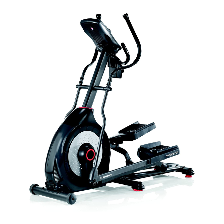
Page 22: Features
feaTures Speakers Foot Pedal Console Transport Handle Media Tray Rail Incline Arm Handlebar Arm Leveler Contact Heart Rate (CHR) Sensors Stabilizer Handlebar, Static Transport Roller Water Bottle Holder Power Connector Storage Bin Fully Shrouded Flywheel Incline Release Button USB Port Incline Adjustment Handle MP3 Input... -
Page 23: Console Features
Console Features The Console provides important information about your workout and lets you control the resistance levels while you exercise. The Console features the Schwinn Dual Track display with touch control buttons to navigate you through the exercise ™ programs. Upper Display 40% 70% 40% 70% QUICK PAUSE/ ST ART Lower Display GOAL TRACK PROGRAMS Resistance Level Quick Buttons CURRENT WORKOUT Resistance Level Quick Buttons LAST WORKOUT LAST 7 DA YS Achievement Indicator Lights Keypad Functions Resistance Increase () button- Increases the workout resistance level Resistance Decrease () button- Decreases the workout resistance level QUICK START button- Begins a Quick Start workout PROGRAMS button- Selects a category and workout program PAUSE / END button- Pauses an active workout, ends a paused workout, or goes back to the previous screen GOAL TRACK button-Displays the Workout Totals and Achievements for the selected User Profile Increase () button- Increases a value (age, time, distance, or calories) or moves through options... - Page 24 Resistance Level Quick Buttons- Shifts the resistance levels to the setting quickly during a workout Achievement Indicator Lights- when a workout result is reviewed, the achievement indicator light will activate. Schwinn Dual Track™ Display Upper Display Data User Display Achievement Display 40% 70% Program Display The Program Display shows information to the User and the grid display area shows the course profile for the program. Each column in the profile shows one interval (workout segment). The higher the column, the higher the resistance level. The flashing column shows your current interval. Intensity Display The Intensity Display shows the level of work at that moment based on the current resistance level. Heart Rate Zone Display The Heart Rate Zone shows which zone the current heart rate value falls into for the current User. These Heart Rate Zones can be used as a workout guide for a certain target zone (anaerobic, aerobic, or fat burn). Consult a physician before you start an exercise program. Stop exercising if you feel pain or tightness in your chest, become short of breath, or feel faint. Contact your doctor before you use the machine again. The heart rate displayed is an approximation and should be used for reference only.
- Page 25 40% 70% Lower Display Data The Lower Display shows the Workout Values and can be customized for each User (Consult the “Edit User Profile” section of this manual). KOUT Speed The Speed display field shows the machine speed in miles per hour (mph) or kilometers per hour (km/h). Time The TIME display field shows the total time count of the workout, the average Time for the User Profile, or the total operational time of the machine. Note: If a Quick Start workout is performed for more than 99 minutes and 59 seconds (99:59), the units for Time will shift to hours and minutes ( 1 hour, 40 minutes ). Distance The Distance display shows the distance count (miles or km) in the workout. Note: T o change the measurement units to English Imperial or metric, refer to the “Console Setup Mode” section in this manual. Level The LEVEL display shows the current resistance level in the workout. The RPM display field shows the pedal revolutions per minute (RPM). Heart Rate (Pulse) The Heart Rate display shows the beats per minute (BPM) from the heart rate monitor. When a heart rate signal is received by the Console, the icon will flash. Consult a physician before you start an exercise program. Stop exercising if you feel pain or tightness in your chest, become short of breath, or feel faint.
- Page 26 Contact Heart Rate Sensors Contact Heart Rate (CHR) sensors send your heart rate signals to the Console. The CHR sensors are the stainless steel parts of the Handlebars. To use, put your hands comfortably around the sensors. Be sure that your hands touch both the top and the bottom of the sensors. Hold firm, but not too tight or loose. Both hands must make contact with the sensors for the Con- sole to detect a pulse.
- Page 27 The graph is a brief guideline, describing the generally suggested target heart rates based on age. As noted above, your opti- mal target rate may be higher or lower. Consult your physician for your individual target heart rate zone. Note: A s with all exercises and fitness regimens, always use your best judgment when you increase your exercise time or intensity.
-
Page 28: Operations
operaTIons What to Wear Wear rubber-soled athletic shoes. You will need the appropriate clothes for exercise that allow you to move freely. How Often Should You Exercise Consult a physician before you start an exercise program. Stop exercising if you feel pain or tightness in your chest, become short of breath, or feel faint. Contact your doctor before you use the machine again. Use the values calcu- lated or measured by the machine’s computer for reference purposes only. The heart rate displayed on the console is an approximation and should be used for reference only. • 3 times a week for 30 minutes each day. • Schedule workouts in advance and try to follow the schedule. Mounting and Dismounting Your Machine Care should be used when mounting or dismounting the machine. -
Page 29: Power Up / Idle Mode
To release the Incline Assembly: Do not adjust the workout angle when on the machine. 1. Grasp the Incline Adjustment Handle and push the Incline Release Button with the palm of your hand. Be prepared to support the weight of the raised parts of the machine. When released, the Incline Assembly may fully disengage. Make sure that you are able to support the weight of the raised parts of the machine safely. Note: The Incline Handle may need to be slightly lifted to disengage the Incline Assembly. 2. L ower to the desired height. In order to avoid possible serious injury when lowering the Rails, be careful to avoid fingers or hands being caught or pinched. -
Page 30: Quick Start Program
Quick Start ( Manual ) Program The Quick Start ( Manual ) program lets you start a workout without entering any information. During a Manual Workout, each column represents a 2 minute time period. The active column will advance across the screen every 2 minutes. If the workout lasts for more than 30 minutes, the active column is fixed on the farthest column on the right and pushes the previous columns off the display. 1. Stand on the machine. 2. P ush the Increase/Decrease button to select the correct User profile. If you do not have a User profile set up, you can select a User profile that has no customized data (default values only). 3. Push the QUICK START button to start the Manual program. 4. T o change the resistance level, push the Resistance Increase/Decrease buttons. The current interval and future intervals are set to the new level. The default Manual resistance level is 4. The time will count up from 00:00. - Page 31 4. T he Console display shows the NAME prompt and the current User Profile name. Note: The User name will be blank if this is the first edit. The name of a User Profile is limited to 10 characters. T he currently active segment will flash. Use the Increase/Decrease buttons to move through the alphabet and blank space (found between A and Z). To set each segment, use the Left() or Right() buttons to shift between segments. P ush the OK button to accept the displayed User name. 5. T o edit the other User data (EDIT AGE, EDIT WEIGHT, EDIT HEIGHT, EDIT GENDER), use the Increase/Decrease buttons to adjust, and push OK to set each entry. 6. T he Console display shows the SCAN prompt. This option controls how the workout values are displayed in the Lower Display during a workout. The “OFF” setting allows the user to push the RIGHT or LEFT buttons to view the other workout value channels when desired. The “ON” setting allows the Console to automatically display the workout value channels every 6 seconds. The default is “OFF”.
- Page 32 5. The Console will now confirm the request to reset the User profile (the default selection is ‘NO’). Push the Increase() or Decrease() buttons to adjust the selection. 6. P ush OK to make your selection. 7. The Console will go to the Power-Up Mode screen. Changing Resistance Levels Push the Resistance Level Increase() or Decrease() buttons to change the resistance level at any time in a workout program. To rapidly change the resistance level, push the desired Resistance Level Quick Button. The Console will adjust to the selected resistance level of the quick button. Profile Programs These programs automate different resistance and workout levels. The Profile Programs are organized into Categories (Fun Rides, Mountains, and Challenges). Note: O nce a User views all the Categories, they will be expanded to display the Programs within each of the Catego- ries. ndary Case 6: Profile Programs Secondary Case 6: Profile Programs FUN RIDES Rolling Hills Ride in the Park Rolling Hills...
- Page 33 Interval Interval Stairs Workout Profile and Goal Program The Console lets you select the Profile Program and type of Goal for your workout (Distance, Time or Calories), and set the Goal value. 1. Stand on the machine. 2. Push the Increase() or Decrease() buttons to select the correct User profile. 3. P ush the Programs button. 4. P ush the Left() or Right() buttons to select a Category of Workout. 5. P ush the Increase() or Decrease() buttons to select a Profile Workout, and push OK. 6. U se the Increase() or Decrease() buttons to select a type of Goal (Distance, Time or Calories), and push OK. 7. U se the Increase() or Decrease() buttons to adjust the workout value.
-
Page 34: Pausing Or Stopping
Heart Rate Control (HRC) Workout Programs The Heart Rate Control (HRC) programs let you set a heart rate goal for your workout. The program monitors your heart rate in beats per minute (BPM) from the Contact Heart Rate (CHR) sensors on the machine, and adjusts the workout to keep your heart rate in the selected zone. Note: The console must be able to read the heart rate information from the CHR sensors for the HRC program to work correctly. The Target Heart Rate programs use your age and other User information to set the Heart Rate Zone values for your workout. The console display then gives prompts for you to set up your workout: 1. S elect the Heart Rate Control workout level: BEGINNER ( “BEG” ) or ADVANCED ( “ADV” ) and push OK. 2. P ush the Increase() and Decrease() buttons to select the percentage of maximum heart rate: 50–60%, 60–70%, 70–80%, 80–90%. Consult a physician before you start an exercise program. Stop exercising if you feel pain or tightness in your chest, become short of breath, or feel faint. Contact your doctor before you use the machine again. Use the values calculated or measured by the machine’s computer for reference purposes only. The heart rate displayed on the console is an approximation and should be used for reference only. -
Page 35: Results / Cool Down Mode
S PEED (average), RPM (average), and HEART RATE (average) c.) T IME (average), LEVEL (average), and CALORIES (average). Push the Left() or Right() buttons to move through the result channels manually. During the Cool Down period, the Resistance Level will adjust to a third of the average Level of the workout. The Cool Down resistance level can be adjusted with the Resistance Increase and Decrease buttons, but the Console will not display the value. You can push PAUSE/END to stop the Results / Cool Down period and go back to Power-Up Mode. If there is no RPM or HR signal, the Console automatically goes into Sleep Mode. GOAL TRACK Statistics (and Achievements) The statistics from every workout are recorded to a User Profile. The Schwinn Dual Track Console shows the Goal Track workout Statistics on the Lower Display in three channels: ™ a.) T IME (total), DISTANCE (total), and CALORIES (total) b.) S PEED (average), RPM (average), and HEART RATE (average) c.) T IME (average), DISTANCE (average) / or LEVEL (average) *, and CALORIES (average) * If the Goal Track Statistic is a single workout, LEVEL (average) is displayed. If the Goal Track Statistic is a combination of multiple workouts, DISTANCE (average) is displayed instead of LEVEL (average). - Page 36 The BMI Measurement is a useful tool that shows the relationship between weight and height that is associated with body fat and health risk. The table below gives a general rating for the BMI score: Underweight Below 18.5 Normal 18.5 – 24.9 Overweight 25.0 – 29.9 Obesity 30.0 and above Note: The rating may overestimate body fat in athletes and others who have a muscular build. It may also underestimate body fat in older persons and others who have lost muscle mass. Contact your doctor for more information about Body Mass Index (BMI) and the weight that is appropriate for you. Use the values calculated or measured by the machine’s computer for reference purposes only. 8. P ush the Increase() button to move to the “SAVE TO USB - OK?” prompt. Push OK, and the “ARE YOU SURE? -NO” prompt will display. Push the Increase() button to change it to yes and push OK. The Console will display the “INSERT USB” prompt. Insert a USB Flash Drive into the USB Port. The Console will record the Statistics to the USB Flash Drive.
-
Page 37: Console Service Mode
Console seTup mode The Console Setup Mode lets you input the date and time, set the units of measurement to either English or Metric, change the machine type, control the sound settings ( on/ off), or see maintenance statistics (Error Log and Run Hours – for service technician use only). 1. H old down the PAUSE/END button and Right button together for 3 seconds while in the Power-Up Mode to go into the Console Setup Mode. Note: Push PAUSE/END to exit the Console Setup Mode and return to the Power-Up Mode screen. 2. T he Console display shows the Date prompt with the current setting. To change, push the Increase/Decrease buttons to adjust the currently active value (flashing). Push the Left/Right buttons to change which segment is the currently active value (month / day / year). 3. P ush OK to set. 4. T he Console display shows the Time prompt with the current setting. Push the Increase/Decrease buttons to adjust the currently active value (flashing). Push the Left/Right buttons to change which segment is the currently active value (hour / minute / AM or PM). 5. P ush OK to set. 6. T he Console display shows the Units prompt with the current setting. To change, push OK to start the Units option. Push the Increase/Decrease buttons to change between “MILES” (Imperial English units) and “KM” (metric units). Note: I f the units change when there is data in User Statistics, the statistics convert to the new units. 7. Push OK to set. -
Page 39: Maintenance
maInTenanCe Read all maintenance instructions fully before you start any repair work. In some conditions, an assistant is required to do the necessary tasks. Equipment must be regularly examined for damage and repairs. The owner is responsible to make sure that regular maintenance is done. Worn or damaged components must be repaired or replaced immediately. Only manufacturer supplied components can be used to maintain and repair the equipment. To reduce the risk of electrical shock or unsupervised usage of the equipment, always unplug the power cord from the wall outlet and the machine and wait 5 minutes before cleaning, maintaining or repairing the machine. Place the power cord in a secure location. Daily: Before each use, examine the exercise machine for loose, broken, damaged, or worn parts. Do not use if found in this condition. Repair or... -
Page 40: Maintenance Parts
Maintenance Parts Console Roller Fly Wheel Heart Rate Cable, Upper Leg, Right Speed Sensor Magnet Handlebar, Static Shroud Cap Speed Sensor Console Cable, Upper Shroud, Upper Pedal Arm, Left Arm Pivot Rod Console Cable, Lower Transport Wheel Console Mast Incline Assembly Front Stabilizer Water Bottle Holder Frame Assembly Leg, Left Handlebar Arm, Lower Right Rail Assembly AC Adapter Handlebar Arm, Upper Right Shroud, Left GG MP3 Cable Pedal Arm, Right Crank Assembly, Left Handlebar Arm, Lower Left Crank Assembly, Right Servo Motor Handlebar Arm, Upper Left Shroud, Right Brake Assembly... -
Page 41: Troubleshooting
TroublesHooTIng Condition/Problem Things to Check Solution No display/partial display/ Check electrical (wall) Make sure unit is plugged into a functioning wall outlet. unit will not turn on outlet Check connection at front Connection should be secure and undamaged. Replace adapter of unit or connection at unit if either are damaged. Check data cable integrity All wires in cable should be intact. If any are visibly crimped or cut, replace cable. Check data cable Be sure cable is connected securely and oriented properly. Small connections/orientation latch on connector should line up and snap into place. - Page 42 Condition/Problem Things to Check Solution No speed/RPM reading, Check data cable integrity All wires in cable should be intact. If any are cut or crimped, Console displays “Please replace cable. Stride” error code Check data cable Be sure cable is connected securely and oriented properly. Small connections/orientation latch on connector should line up and snap into place. Check magnet position Magnet should be in place on pulley. (requires shroud removal) Check Speed Sensor (re- Speed sensor should be aligned with magnet and connected to quires shroud removal) data cable. Realign sensor if necessary. Replace if there is any damage to the sensor or the connecting wire.
- Page 43 Condition/Problem Things to Check Solution Drive train click/tick noise Check crank/pulley as- Disconnect left and right foot assemblies and rotate crank. If once per full crank revolu- sembly sound persists, replace crank/pulley assembly. If sound does tion not come from rotating crank, check foot assemblies and upper/ lower handlebars. Check foot assemblies, leg Manually move foot, leg, and handlebar assemblies to isolate assemblies, handlebar sound. Replace part making sound. assemblies Squeaking noise that ap- Bolt that connects the Loosen pivot rod bolt slightly until noise goes away. See video pears a few minutes into swing arms to the axle run- for demonstration. White lithium grease can also be applied for a a workout and normally will ning through the console temporary fix. Contact Customer Care for assistance. get progressively worse as mast the workout continues...
-
Page 45: Warranty
WarranTy Who Is Covered This warranty is valid only to the original purchaser and is not transferable or applicable to any other person(s). What Is Covered Nautilus, Inc. warrants that this product is free from defects in materials and workmanship, when used for the purpose intended, under normal conditions, and provided it receives proper care and maintenance as described in the Product’s Assembly and Owner’s manual. - Page 46 Nautilus Bowflex Schwinn Fitness Universal ® ® ® ® 8002138.080113.B...
Need help?
Do you have a question about the 430 Elliptical 2013 model and is the answer not in the manual?
Questions and answers