Innova OBD2 Owner's Manual
Diagnostic tool
Hide thumbs
Also See for OBD2:
- Owner's manual (138 pages) ,
- Owner's manual (32 pages) ,
- Owner's manual (56 pages)
Table of Contents
Advertisement
Advertisement
Table of Contents

Related Manuals for Innova OBD2


Summary of Contents for Innova OBD2
-
Page 2: Table Of Contents
CONTROLS AND INDICATORS ..........DISPLAY FUNCTIONS ............ONBOARD DIAGNOSTICS COMPUTER ENGINE CONTROLS ......... DIAGNOSTIC TROUBLE CODES (DTCs) ......OBD2 MONITORS ..............PREPARATION FOR TESTING PRELIMINARY VEHICLE DIAGNOSTIC WORKSHEET ..BEFORE YOU BEGIN .............. VEHICLE SERVICE MANUALS ..........USING THE DIAGNOSTIC TOOL CODE RETRIEVAL PROCEDURE .......... -
Page 3: Introduction What Is Obd
Then came the development of OBD2, which is on all 1996 and newer vehicles sold in the U.S. Like its predecessor, OBD2 was adopted as part of a government mandate to lower vehicle emissions. But what makes OBD2 unique is its universal application for all late model cars and trucks - domestic and import. -
Page 4: You Can Do It
Freeze Frame data are displayed on the Diagnostic Tool’s LCD display screen. System status is indicated by LED indicators. Easy To Define ..Read code definitions from Diagnostic Tool’s LCD display. View Freeze Frame data. OBD2... -
Page 5: Safety Precautions Safety First
SAFETY FIRST! SAFETY FIRST! To avoid personal injury, instrument damage and/or damage to your vehicle; do not use the OBD2 Code Reader before reading this manual. This manual describes common test procedures used by experienced service technicians. Many test procedures... - Page 6 Safety Precautions SAFETY FIRST! To prevent damage to the on-board computer when taking vehicle electrical measurements, always use a digital multimeter with at least 10 megOhms of impedance. Fuel and battery vapors are highly flammable. To prevent an explosion, keep all sparks, heated items and open flames away from the battery and fuel / fuel vapors.
-
Page 7: About The Diagnostic Tool
United States must be OBD2 compliant; this includes all Domestic, Asian and European vehicles. Some 1994 and 1995 vehicles are OBD2 compliant. To find out if a 1994 or 1995 vehicle is OBD2 compliant, check the following: 1. -
Page 8: Battery Replacement
The Diagnostic Tool lets you make several adjustments and settings to configure the Diagnostic Tool to your particular needs. It also contains an OBD2 DTC Library that allows you to search for DTC definitions. The following functions, adjustments and settings can be performed when the Diagnostic Tool is in “MENU Mode”:... - Page 9 3. Press the DOWN button to increase the brightness of the LCD display (make the display lighter). 4. When the desired brightness is obtained, press the ENTER/FF button to save your changes and return to the MENU. OBD2...
- Page 10 LCD display. - If the correct manufacturer is shown, press the ENTER/FF button to continue. - If the correct manufacturer is not shown, press the DTC SCROLL button to return to the list of vehicle manufacturers. OBD2...
- Page 11 Measure in the MENU, then press the ENTER/FF button. 2. Press the UP or DOWN button, as necessary, to highlight the desired Unit of Measure. 3. When the desired Unit of Measure value is selected, press the ENTER/FF button to save your changes. OBD2...
- Page 12 Menu Exit in the MENU, then press the ENTER/FF button. The LCD display returns to the DTC screen (if data is currently stored in the Diagnostic Tool’s memory) or the “To Link” screen (if no data is stored). OBD2...
-
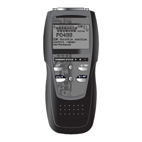
Page 13: Diagnostic Tool Controls Controls And Indicators
To turn the Diagnostic Tool "On", you must press and hold the POWER/LINK button for approximately 3 seconds. ENTER/FREEZE FRAME button - When in MENU mode, confirms the selected option or value. When retrieving and viewing DTCs, displays Freeze Frame data for the highest priority code. OBD2... - Page 14 10. LCD Display - Displays settings Menu and submenus, test results, Diagnostic Tool functions and Monitor status information. See DISPLAY FUNCTIONS, on next page, for more details. 11. CABLE - Connects the Diagnostic Tool to the vehicle’s Data Link Connector (DLC). OBD2...
-
Page 15: Display Functions
"on", all 3 LEDs will light up as a last resort indicator to warn you that the batteries need replacement. No data will be displayed on screen when all 3 LEDs are lit. OBD2... - Page 16 “Freeze Frame” data has been stored. If “01” is a “Pending” code, there may or may not be “Freeze Frame” data stored in memory. 14. Code Enumerator - Indicates the total number of codes retrieved from the vehicle’s computer. OBD2...
-
Page 17: Onboard Diagnostics Computer Engine Controls
By switching from mechanical to electronic engine controls, vehicle manufacturers are able to control fuel delivery and spark timing more precisely. Some newer Computer Control Systems also provide control over other vehicle functions, such as transmission, brakes, charging, body, and suspension systems. OBD2... - Page 18 EGR valve or Ignition Module to perform these actions. TYPICAL COMPUTER OUTPUT DEVICES CONTROL SYSTEM Fuel Injectors Idle Air Control EGR Valve Ignition Module On-Board Computer INPUT DEVICES Coolant Temperature Sensor INPUT DEVICES Throttle Position Sensor Oxygen Sensors Fuel Injectors OBD2...
- Page 19 These codes can be retrieved from the computer’s memory with the use of a “Code Reader” or a “Scan Tool.” On-Board Diagnostics - Second Generation (OBD2) addition performing...
- Page 20 This new system is known as “On-Board Diagnostics Generation Two (OBD2).” The primary objective of the OBD2 system is to comply with the latest regulations and emissions standards established by CARB and the EPA.
- Page 21 Onboard Diagnostics COMPUTER ENGINE CONTROLS Powertrain Control Module (PCM) - The PCM is the OBD2 accepted term for the vehicle’s “on-board computer.” In addition to controlling the engine management and emissions systems, also participates in controlling the powertrain (transmission) operation. Most PCMs also have the ability to communicate with other computers on the vehicle (ABS, ride control, body, etc.).
-
Page 22: Diagnostic Trouble Codes (Dtcs)
Onboard Diagnostics DIAGNOSTIC TROUBLE CODES (DTCs) OBD2 Drive Cycle - An OBD2 Drive Cycle is an extended set of driving procedures that takes into consideration the various types of driving conditions encountered in real life. These conditions may include starting the vehicle when it is cold, driving the vehicle at a steady speed (cruising), accelerating, etc. - Page 23 The Federal Government does not require vehicle manufacturers to go beyond the standardized generic DTCs in order to comply with the new OBD2 emissions standards. However, manufacturers are free to expand beyond the standardized codes to make their systems easier to diagnose.
- Page 24 If the failure is not found on the second Trip, the Pending DTC is erased from the computer’s memory. The MIL will stay lit for both Type “A” and Type “B” codes until one of the following conditions occurs: OBD2...
-
Page 25: Obd2 Monitors
Currently, fifteen Monitors are supported by OBD2 systems. Additional monitors may be added as a result of Government regulations as the OBD2 system grows and matures. Not all vehicles support all fifteen Monitors. Additionally, some Monitors are supported by “spark ignition”... - Page 26 Onboard Diagnostics OBD2 MONITORS Non-Continuous Monitors The other twelve Monitors are “non-continuous” Monitors. “Non- continuous” Monitors perform and complete their testing once per trip. The “non-continuous” Monitors are: Oxygen Sensor Monitor Oxygen Sensor Heater Monitor Catalyst Monitor Heated Catalyst Monitor...
- Page 27 Onboard Diagnostics OBD2 MONITORS Fuel System Monitor - This Monitor uses a Fuel System Correction program, called Fuel Trim, inside the on-board computer. Fuel Trim is a set of positive and negative values that represent adding or subtracting fuel from the engine. This program is used to correct for a lean (too much air/not enough fuel) or rich (too much fuel/not enough air) air-fuel mixture.
- Page 28 MIL “On,” and saves the code in its long-term memory. Evaporative System (EVAP) Monitor - OBD2 vehicles are equipped with a fuel Evaporative system (EVAP) that helps prevent fuel vapors from evaporating into the air. The EVAP system carries fumes from the fuel tank to the engine where they are burned during combustion.
- Page 29 Onboard Diagnostics OBD2 MONITORS into the engine where the vapors are burned. The EVAP Monitor checks for proper fuel vapor flow to the engine, and pressurizes the system to test for leaks. The computer runs this Monitor once per trip.
- Page 30 Onboard Diagnostics OBD2 MONITORS exhaust stream. A faulty oxygen sensor reacts slowly, or its voltage signal is weak or missing. The Oxygen Sensor Monitor is supported by “spark ignition” vehicles only. The Oxygen Sensor Monitor is a “Two-Trip” monitor. If a fault is found on the first trip, the computer temporarily saves the fault in its memory as a Pending Code.
- Page 31 Onboard Diagnostics OBD2 MONITORS NOx Aftertreatment Monitor - NOx aftertreatment is based on a catalytic converter support that has been coated with a special washcoat containing zeolites. NOx Aftertreatment is designed to reduce oxides of nitrogen emitted in the exhaust stream. The zeolite acts as a molecular "sponge"...
- Page 32 If the fault is sensed again on the second trip, the computer commands the MIL “On,” and saves the code in its long-term memory. OBD2 Reference Table The table below lists current OBD2 Monitors, and indicates the following for each Monitor: Monitor Type (how often does the Monitor run; Continuous or...
- Page 33 Onboard Diagnostics OBD2 MONITORS Name of Monitor Comprehensive Continuous Component Monitor Misfire Monitor 3 - similar Continuous (Type 1 and 3) conditions Misfire Monitor 3 - similar Continuous (Type 2) conditions Fuel System Monitor 3 - similar Continuous 1 or 2...
-
Page 34: Preparation For Testing Preliminary Vehicle Diagnostic Worksheet
*VIN: Vehicle Identification Number, found at the base of the windshield on a metallic plate, or at the driver door latch area (consult your vehicle owner's manual for location). TRANSMISSION: ❏ Automatic ❏ Manual Please check all applicable items in each category. DESCRIBE THE PROBLEM: OBD2... - Page 35 No symptoms Backfires ❏ ❏ Runs rough Misfires or cuts out ❏ ❏ Lacks power Engine knocks, pings or rattles ❏ Bucks and jerks ❏ Surges ❏ Poor fuel economy ❏ Dieseling or run-on ❏ Hesitates or stumbles on accelerations OBD2...
- Page 36 CHECK ENGINE LIGHT / DASH WARNING LIGHT ❏ ❏ ❏ Sometimes ON Always ON Never ON PECULIAR SMELLS ❏ ❏ "Hot" Gasoline ❏ ❏ Sulfur ("rotten egg") Burning oil ❏ ❏ Burning rubber Electrical STRANGE NOISES ❏ ❏ Rattle Squeak ❏ ❏ Knock Other OBD2...
-
Page 37: Before You Begin
Check all electrical wiring and harnesses for proper connection. Make sure wire insulation is in good condition, and there are no bare wires. Make sure the engine is mechanically sound. If needed, perform a compression check, engine vacuum check, timing check (if applica- ble), etc. OBD2... -
Page 38: Vehicle Service Manuals
Poway, California 92064 Phone: 888-724-6742 Motor Publications 5600 Crooks Road, Suite 200 Troy, Michigan 48098 Phone: 800-426-6867 FACTORY SOURCES Ford, GM, Chrysler, Honda, Isuzu, Hyundai and Subaru Service Manuals Helm Inc. 14310 Hamilton Avenue Highland Park, Michigan 48203 Phone: 800-782-4356 OBD2... -
Page 39: Using The Diagnostic Tool Code Retrieval Procedure
Diagnostic Tool. Refer to your vehicle’s service manual to properly check the vehicle’s DLC. 4. When the Diagnostic Tool’s cable connector is properly connected to the vehicle’s DLC, the unit automatically turns ON, and links to the vehicle’s on- board computer. OBD2... - Page 40 ON. - Turn the ignition OFF, wait 5 seconds, then turn back ON to reset the computer. - Ensure your vehicle is OBD2 compliant. See VEHICLES COVERED on page 5 for vehicle compliance verification information.
- Page 41 If the FREEZE FRAME icon is lit when the “Priority Code” (Code #1) is displayed on the Diagnostic Tool’s screen, it indicates that there is Freeze Frame data associated with this code, and the vehicle’s computer has saved it in its memory. OBD2...
- Page 42 Check the Diagnostic Tool’s LCD display for confirmation. All Monitor icons that are blinking have not yet run and completed their diagnostic testing; all Monitor icons that are solid have run and completed their diagnostic testing. OBD2...
- Page 43 DTC’s that start with “P0”, “P2” and some “P3” are considered Generic (Universal). All Generic DTC definitions are the same OBD2 equipped vehicles. Diagnostic Tool automatically displays the code definitions for Generic DTC’s.
- Page 44 DTCs for your vehicle. If you do not wish to view enhanced DTCs, press the DTC SCROLL button to return to the OBD2 DTC screen. 12. Determine engine system(s) condition by viewing the Diagnostic Tool’s LCD display for any retrieved Diagnostic Trouble Codes, code definitions, Freeze Frame data and interpreting the green, yellow and red LEDs.
-
Page 45: The Enhanced Main Menu
Vehicle information is available for model year 2000 and newer OBD2-compliant vehicles only. The screen shown when the Diagnostic Tool enters the “enhanced” mode depends on the type(s) of DTC(s) returned during the code... - Page 46 If the manufacturer of the vehicle from which codes were retrieved is not listed, press the DTC SCROLL button to return to the OBD2 DTC screen. Enhanced data is not available for your vehicle. If a Manufacturer specific DTC was...
-
Page 47: Viewing Enhanced Dtcs
Refer to DISPLAY FUNCTIONS on page 13 for a description of LCD display elements. A visible icon indicates that the Diagnostic Tool is being powered through the vehicle’s DLC connector. A visible icon indicates that the Diagnostic Tool is linked to (communicating with) the vehicle’s computer. OBD2... - Page 48 DOWN buttons, as necessary, to select Exit from the Chrysler Enhanced menu, then press the ENTER/FF button. The Diagnostic Tool returns to the OBD2 DTC screen. Ford/Mazda Enhanced DTCs Mazda Enhanced DTCs are available for Mazda-branded Ford vehicles only.
- Page 49 The Diagnostic Trouble Code (DTC) and related code definition are shown in the lower section of the LCD display. I/M MONITOR STATUS icons are not displayed when viewing enhanced DTCs. OBD2...
- Page 50 Exit from the Ford/Mazda Enhanced menu, then press the ENTER/FF button. The Diagnostic Tool returns to the OBD2 DTC screen. General Motors/Isuzu Enhanced DTCs When View Enhanced DTCs is selected from the Enhanced Main Menu (and GM/Isuzu is selected, if prompted), the GM/Isuzu Enhanced menu displays.
- Page 51 Diagnostic Tool’s communication link with the vehicle’s computer disconnects. To re-establish communication, press the LINK button again. 4. When the last retrieved DTC has been displayed and the DTC SCROLL button is pressed, the Diagnostic Tool returns to the GM/Isuzu Enhanced menu. OBD2...
-
Page 52: Viewing Vehicle Information
DOWN buttons, as necessary, to select Exit from the GM/Isuzu Enhanced menu, then press the ENTER/FF button. The Diagnostic Tool returns to the OBD2 DTC screen. VIEWING VEHICLE INFORMATION When you select View Vehicle Info from the Enhanced Main... -
Page 53: Erasing Diagnostic Trouble Codes (Dtcs)
4. When you have finished viewing the list of available modules, press the ENTER/FF button to the OBD2 DTC screen. The Diagnostic information retrieved can be transferred to a personal computer (PC) with the use of an optional Tek-Link program. - Page 54 I/M Readiness Monitor Status program resets the status of all Monitors to a not run "flashing" condition. To set all of the Monitors to a DONE status, an OBD2 Drive Cycle must be performed. Refer to your vehicle's service manual for information on how to perform an OBD2 Drive Cycle for the vehicle under test.
-
Page 55: I/M Readiness Testing
Emissions Tests are generally performed once a year, or once every two years. On OBD2 systems, the I/M program is enhanced by requiring vehicles to meet stricter test standards. One of the tests instituted by the Federal Government is called I/M 240. On I/M 240, the vehicle under... - Page 56 Using the Diagnostic Tool I/M READINESS TESTING To learn more about Emissions Inspection and Maintenance (I/M) Readiness Monitors, see OBD2 MONITORS on page 22. Each Monitor has a specific function to test and diagnose only its designated emissions- related component or system. The names of the Monitors (Oxygen Sensor Monitor, Catalyst Monitor, EGR Monitor, Misfire Monitor, etc.)
- Page 57 Currently, most areas (states / countries) will allow an Emissions Test (Smog Check) to be performed if the only code in the vehicle's computer is a "PENDING" Diagnostic Trouble Code. OBD2...
- Page 58 Take the vehicle to a professional to have it serviced. The problem(s) causing the red LED to light must be repaired before the vehicle is ready for an Emissions Test (Smog Check). OBD2...
- Page 59 One person should drive the vehicle while the other person observes the Monitor icons on the Diagnostic Tool for Monitor RUN status. Trying to drive and observe the Diagnostic Tool at the same time is dangerous, and could cause a serious traffic accident. OBD2...
- Page 60 If, after the Monitor has run, the MIL on the vehicle's dash lights and/or a DTC associated with that Monitor is present in the vehicle's computer, the repair was unsuccessful. Refer to the vehicle's service manual and recheck repair procedures. OBD2...
-
Page 61: Glossary
FTP – Fuel Tank Pressure Generic Code – A DTC that applies to all OBD2 compliant vehicles. I/M Readiness – An indication of whether or not a vehicle’s emissions- related system are operating properly and are ready for Inspection and Maintenance testing. - Page 62 MIL – Malfunction Indicator Lamp (also referred to as “Check Engine” light OBD1 – On-Board Diagnostics Version 1 (also referred to as “OBD I”) OBD2 – On-Board Diagnostics Version 2 (also referred to as “OBD II”) On-Board Computer – The central processing unit in the vehicle’s computer control system.
-
Page 63: Warranty And Servicing
UPDATES and OPTIONAL ACCESSORIES, please contact your local store, distributor or the Service Center. USA & Canada: (800) 544-4124 (5:00 AM-6:00 PM, Monday-Friday PST) All others: (714) 241-6802 (5:00 AM-6:00 PM, Monday-Friday PST) FAX: (714) 432-7511 (24 hr.) Web: www.CanOBD2.com OBD2... - Page 64 ® Innova Electronics Corp. 17291 Mt. Herrmann Street Fountain Valley, CA 92708 Printed in Taiwan Instruction MRP #93-0093 Rev. D © 2009 Copyright © 2009 IEC. All Rights Reserved.
Need help?
Do you have a question about the OBD2 and is the answer not in the manual?
Questions and answers