Innova OBD2 Owner's Manual
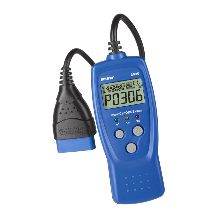
Car reader
Hide thumbs
Also See for OBD2:
- Owner's manual (138 pages) ,
- Owner's manual (64 pages) ,
- Owner's manual (72 pages)
Table of Contents
Advertisement
Quick Links
Advertisement
Table of Contents

Related Manuals for Innova OBD2


Summary of Contents for Innova OBD2
- Page 1 +)4 4-),-4...
-
Page 2: Table Of Contents
Include your name, return address, and a day contact phone Enclose a copy of the dated sales receipt Describe the problem Ship prepaid to: Technical Service Center, 17291 Mt. Herrmann Street, Fountain Valley, CA 92708 U.S.A. Phone: 1-800-544-4124 or 714-241-6805 Fax: 714-432-7910 Web: www.iEQUUS.com Email: service@iEQUUS.com OBD2... -
Page 3: You Can Do It
The Car Reader retrieves stored codes and displays I/M Readiness status. Codes are displayed on the Car Reader’s LCD display screen; I/M Readiness status is displayed by LED indicators. Easy To Define ..Locate fault code(s) in the Fault Code Definition list. OBD2... -
Page 4: Safety Precautions
Code Reader from the vehicle’s Data Link Connector (DLC). To prevent damage to the on-board computer when taking vehicle electrical measurements, always use a digital multimeter with at least 10 megOhms of impedance. The vehicle's battery produces highly flammable hydrogen gas. To prevent an explosion, keep all sparks, heated items and open flames away from the battery. -
Page 5: About The Car Reader
On some Asian and European vehicles the DLC is located behind the “ashtray” (the ashtray must be removed to access it) or on the far left corner of the dash. If the DLC cannot be located, consult the vehicle’s service manual for the location. OBD2... -
Page 6: Controls And Indicators
Monitors on the vehicle are active and performing their diagnostic testing, and no DTCs are present). YELLOW LED - Indicates there is a possible problem. A “Pending” DTC is present and/or some of the vehicle's emission monitors have not run their diagnostic testing. OBD2... -
Page 7: Display Functions
MIL icon is visible only when a DTC has commanded the MIL on the vehicle's dashboard to light. 7. FREEZE FRAME icon - Indicates that “Freeze Frame” data has been stored in the vehicle’s computer for the currently displayed DTC. OBD2... - Page 8 Following is a list of Monitor icons and their associated Monitors. Misfire Monitor Fuel System Monitor Comprehensive Component Monitor Catalyst Monitor Heated Catalyst Monitor Evaporative System Monitor Secondary Air System Monitor Air Conditioning System Refrigerant (R-12) Monitor Oxygen Sensor Monitor Oxygen Sensor Heater Monitor Exhaust Gas Recirculation (EGR) Monitor OBD2...
-
Page 9: Preparation For Testing
Phone: 888-724-6742 Motor Publications - 5600 Crooks Road, Suite 200 , Troy, Michigan 48098 Phone: 800-426-6867 FACTORY SOURCES Ford, GM, Chrysler, Honda, Isuzu, Hyundai and Subaru Service Manuals Helm Inc.- -14310 Hamilton Avenue, Highland Park, Michigan 48203 Phone: 800-782-4356 OBD2... -
Page 10: Using The Code Reader
If an error message (Err, Err1 or Err2) is shown on the Car Reader’s LCD display, it indicates there is a communication problem. This means that the Car Reader is unable to communicate with the vehicle's computer. Do the following: OBD2... - Page 11 The red LED is also used to show that DTC(s) are present (displayed on the Car Reader’s LCD display). In this case, the Multifunction Indicator (Check Engine) lamp on the vehicle's instrument panel will light steady on. OBD2...
-
Page 12: Erasing Diagnostic Trouble Codes (Dtcs)
DLC. (If the Car Reader is already connected and linked to the vehicle's computer, proceed directly to step 4. If not, continue to step 2. Turn the ignition on. DO NOT start the engine. The Car Reader will automatically link to the vehicle’s computer. OBD2... - Page 13 If proper repairs to correct the problem that caused the code(s) to be set are not made, the code(s) will appear again (and the check engine light will illuminate) as soon as the vehicle is driven long enough for its Monitors to complete their testing. OBD2...
-
Page 14: Dtc Definitions
OBD 2 is an evolving system; new codes and definitions are added as the system grows. ALWAYS check your vehicle's service manual for code definitions that are not listed here, or for “Manufacturer- Specific” DTC definitions. For more information, visit our web site at www.CodeReader.com. OBD2... - Page 15 Fuel and Air Metering Fuel and Air Metering (injector circuit malfunction only) Ignition System or Misfire Auxiliary Emission Control System Vehicle Speed Control and Idle Control System Computer Output Circuits Transmission Transmission Identifies what section of the system is malfunctioning OBD2...
- Page 16 Ambient Air Temperature Sensor Circuit P0071 Ambient Air Temperature Sensor Range/Performance P0072 Ambient Air Temperature Sensor Circuit Low Input P0073 Ambient Air Temperature Sensor Circuit High Input P0074 Ambient Air Temperature Sensor Circuit Intermittent P0075 Intake Valve Control Solenoid Circuit (Bank 1) OBD2...
- Page 17 Throttle/Pedal Position Sensor/Switch A Circuit High Input P0124 Throttle/Pedal Position Sensor/Switch A Circuit Intermittent P0125 Insufficient Coolant Temperature for Closed Loop Fuel Control P0126 Insufficient Coolant Temperature for Stable Operation P0127 Intake Air Temperature Too High P0128 Coolant Thermostat (Coolant Temperature Below Thermostat Regulating Temperature) OBD2...
- Page 18 O2 Sensor Circuit No Activity Detected (Bank 2 Sensor 3) P0167 O2 Sensor Heater Circuit Malfunction (Bank 2 Sensor 3) P0168 Fuel Temperature Too High P0169 Incorrect Fuel Composition P0170 Fuel Trim Malfunction (Bank 1) P0171 System too Lean (Bank 1) OBD2...
- Page 19 Injector Circuit Malfunction - Cylinder 8 P0209 Injector Circuit Malfunction - Cylinder 9 P0210 Injector Circuit Malfunction - Cylinder 10 P0211 Injector Circuit Malfunction - Cylinder 11 P0212 Injector Circuit Malfunction - Cylinder 12 P0213 Cold Start Injector 1 Malfunction OBD2...
- Page 20 Turbocharger Wastegate Solenoid B Low P0250 Turbocharger Wastegate Solenoid B High P0251 Injection Pump A Rotor/Cam Malfunction P0252 Injection Pump A Rotor/Cam Range/Performance P0253 Injection Pump A Rotor/Cam Low P0254 Injection Pump A Rotor/Cam High P0255 Injection Pump A Rotor/Cam Intermitted OBD2...
- Page 21 P0291 Cylinder 11 Injector Circuit Low P0292 Cylinder 11 Injector Circuit High P0293 Cylinder 11 Contribution/Balance Fault P0294 Cylinder 12 Injector Circuit Low P0295 Cylinder 12 Injector Circuit High P0296 Cylinder 12 Contribution/Balance Fault P0298 Engine Oil Over Temperature OBD2...
- Page 22 Camshaft Position Sensor Circuit Range/Performance P0342 Camshaft Position Sensor Circuit Low Input P0343 Camshaft Position Sensor Circuit High Input P0344 Camshaft Position Sensor Circuit Intermittent P0345 Camshaft Position Sensor "A" Circuit (Bank 2) P0346 Camshaft Position Sensor "A" Circuit Range/Performance (Bank 2) OBD2...
- Page 23 Crankshaft Position Sensor B Circuit High Input P0389 Crankshaft Position Sensor B Circuit Intermittent P0390 Camshaft Position Sensor "B" Circuit (Bank 2) P0391 Camshaft Position Sensor "B" Circuit Range/Performance (Bank 2) P0392 Camshaft Position Sensor "B" Circuit Low Input (Bank 2) OBD2...
- Page 24 Heated Catalyst Temperature Below Threshold (Bank 2) P0435 Catalyst Temperature Sensor (Bank 2) P0436 Catalyst Temperature Sensor Range/Performance (Bank 2) P0437 Catalyst Temperature Sensor Low Input (Bank 2) P0438 Catalyst Temperature Sensor High Input (Bank 2) P0439 Catalyst Heater Control Circuit (Bank 2) OBD2...
- Page 25 P0478 Exhaust Pressure Control Valve High P0479 Exhaust Pressure Control Valve Intermittent P0480 Cooling Fan 1 Control Circuit Malfunction P0481 Cooling Fan 2 Control Circuit Malfunction P0482 Cooling Fan 3 Control Circuit Malfunction P0483 Cooling Fan Rationality Check Malfunction OBD2...
- Page 26 Exhaust Gas Temperature Sensor Circuit High (Bank 1) P0547 Exhaust Gas Temperature Sensor Circuit (Bank 2) P0548 Exhaust Gas Temperature Sensor Circuit Low (Bank 2) P0549 Exhaust Gas Temperature Sensor Circuit High (Bank 2) P0550 Power Steering Pressure Sensor Circuit Malfunction OBD2...
- Page 27 Starter Relay Circuit P0616 Starter Relay Circuit Low P0617 Starter Relay Circuit High P0618 Alternative Fuel Control Module KAM Error P0619 Alternative Fuel Control Module RAM/ROM Error P0620 Generator Control Circuit Malfunction P0621 Generator Lamp "L" Control Circuit Malfunction OBD2...
- Page 28 Transmission Fluid Temperature Sensor Circuit Malfunction P0711 Transmission Fluid Temperature Sensor Circuit Range/Performance P0712 Transmission Fluid Temperature Sensor Circuit Low Input P0713 Transmission Fluid Temperature Sensor Circuit High Input P0714 Transmission Fluid Temperature Sensor Circuit Intermittent P0715 Input/Turbine Speed Sensor Circuit Malfunction OBD2...
- Page 29 Shift Solenoid A Stuck On P0753 Shift Solenoid A Electrical P0754 Shift Solenoid A Intermittent P0755 Shift Solenoid B Malfunction P0756 Shift Solenoid B Performance or Stuck Off P0757 Shift Solenoid B Stuck On P0758 Shift Solenoid B Electrical OBD2...
- Page 30 P0795 Pressure Control Solenoid "C" P0796 Pressure Control Solenoid "C" Performance or Stuck Off P0797 Pressure Control Solenoid "C" Stuck On P0798 Pressure Control Solenoid "C" Electrical P0799 Pressure Control Solenoid "C" Intermittent P0801 Reverse Inhibit Control Circuit Malfunction OBD2...
- Page 31 P0845 Transmission Fluid Pressure Sensor/Switch "B" Circuit P0846 Transmission Fluid Pressure Sensor/Switch "B" Circuit Range/Performance P0847 Transmission Fluid Pressure Sensor/Switch "B" Circuit Low P0848 Transmission Fluid Pressure Sensor/Switch "B" Circuit High P0849 Transmission Fluid Pressure Sensor/Switch "B" Circuit Intermittent OBD2...
- Page 32 ® Innova Electronics Corp. PRODUCT DESIGN & COPYRIGHT 17291 Mt. Herrmann Street Fountain Valley, CA 92708 Printed in Taiwan © 2004 Instruction MRP #93-0058...
Need help?
Do you have a question about the OBD2 and is the answer not in the manual?
Questions and answers