
Related Manuals for Bosch LTC 8500


Summary of Contents for Bosch LTC 8500
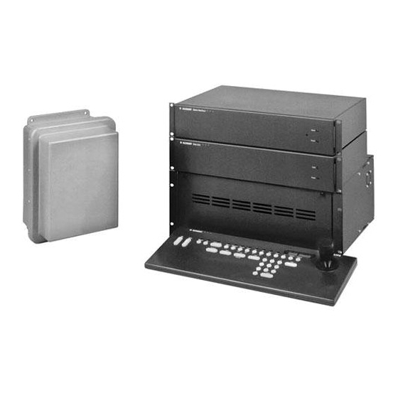
- Page 1 LTC 8500 Series Instruction Manual Allegiant Microprocessor- based Video Switcher/ Control Systems BOSCH...
- Page 2 Bosch Security Systems | December 13, 2005 EN | ii...
-
Page 3: Important Safeguards
Product | Instruction Manual | Important Safeguards Important Safeguards 1. Read, Follow, and Retain Instructions - All safety 10. Power Sources - Operate the unit only from the type and operating instructions should be read and of power source indicated on the label. If unsure of followed before operating the unit. -
Page 4: Safety Precautions
The equipment must not exceed its maximum operating temperature requirements. 2. Mechanical Loading - When rack-mounting the equipment, ensure that a hazardous condition is not created by uneven mechanical loading. Bosch Security Systems | December 13, 2005 EN | iv... - Page 5 Product | Instruction Manual | FCC & ICES Information FCC & ICES INFORMATION Sicherheitshinweise (U.S.A. and Canadian Models Only) This device complies with part 15 of the FCC Rules. Operation is subject to the following two conditions: This device may not cause harmful interference, and This device must accept any interference received, including interference that may cause undesired VORSICHT: UM EINEN ELEKTRISCHEN SCHLAG ZU...
- Page 6 L'unità è tuttavia in funzione solo quando l'interruttore ON-OFF si trova nella posizione ON. Il cavo di alimentazione costituisce il dispositivo di scollegamento dell'alimentazione principale per tutte le unità. Bosch Security Systems | December 13, 2005 EN | vi...
-
Page 7: Table Of Contents
Video Output Modules ........................17 CPU Module ............................17 Camera and Monitor Video Connections ..................18 Termination Practices .......................... 18 7.6.1 LTC 8500 Series Video Terminations ..................18 7.6.2 Monitor Output Video Connections..................18 8. Optional Accessories Installation ........................ 19 General Accessory Installation......................19 Logging Printer Option Installation .................... - Page 8 16.4.5 Recording a Camera Pre-position Scene ................... 46 16.4.6 Recalling a Camera Pre-position Scene..................46 16.4.7 Activate/Deactivate Auxiliary Function ..................46 16.5 Alarm Commands ..........................47 16.5.1 Arm/Disarm Individual Alarms ....................47 16.5.2 Arm/Disarm All Alarms......................48 EN | viii Bosch Security Systems | December 13, 2005...
- Page 9 16.5.3 Arm/Disarm Monitor ........................48 16.5.4 Alarms Acknowledgement ......................48 16.6 Sequence Control ..........................48 16.6.1 Load/Clear a Sequence ....................... 48 16.6.2 Run a Sequence ..........................49 16.6.3 Stop a Running Sequence ......................49 16.6.4 Controlling Sequence Direction ....................49 16.7 Sequence Programming ........................
- Page 10 AC Line Fuse Replacement ........................ 66 18.4 Power Supply Fuse Replacement ....................... 66 18.5 Replacement of Memory Backup Batteries ..................66 19. Character ROM Tables for LTC 8500......................68 20. Error Messages ..............................70 21. Troubleshooting Guide ..........................73 21.1 Main Bay Checkout ..........................73 21.2...
-
Page 11: Unpacking
This equipment should be unpacked and handled with care. If an item appears to have been damaged in shipment, notify the shipper. Verify that all parts shown in the Parts List have been included. If any items are missing, notify your Bosch Secu- rity Systems Sales or Customer Service Representative. -
Page 12: Service
Service If the unit needs repair, contact the nearest Bosch Security Systems Service Center for authorization to return and shipping instructions. Service Centers • • Phone: 800-366-2283 or 717-735-6638 • Fax: 800-366-1329 or 717-735-6639 • CCTV Spare Parts • Phone: 800-894-5215 or 408-956-3853 or 3854 •... -
Page 13: Description
The LTC 8500 Series Allegiant system can handle up to 64 cameras and eight (8) monitors in a full crosspoint configuration. It can also accommodate 128 alarm points, up to eight (8) system keyboards, a computer system console port, and a log- ging printer port. - Page 14 When these models are used in this type of configuration, the main system can access up to 256 cameras located anywhere in the system. EN | 4 Bosch Security Systems | December 13, 2005...
-
Page 15: Allegiant Feature Summary Table
Allegiant Feature Summary Table This Allegiant Series system is available in two (2) operating configurations: a base system and the base system with an optional PC based software package. The base system includes features required for most switching/controller systems. The addition of the optional LTC 8059/00 MCS or optional LTC 8850/00 GUI Software package enables the user to customize the system's configuration using a ®... - Page 16 The LTC 8500 Series system contains a logging printer output port, so an inexpen- sive RS-232 serial printer or some other form of logging software can be used to capture log data. This provides a permanent record showing time and date of changes to system status, such as: •...
-
Page 17: System Components
LTC 8501 Series Systems System Components 5. 1 LTC 8501 Series Systems • LTC 8501 Series Main CPU Bay A modular equipment bay which contains the system’s microprocessor module (LTC 8511/00), the power supply module (LTC 8505 Series), and combinations of video input and video output modules (see below). -
Page 18: System Accessory Components
Divar Series DVRs, System4 Series multiplexers, and access ADIM based DVR control screens. KBD-Rack Keyboard Mounting Kit Rack-mounting kit designed to provide vertical, horizontal, or inclined mounting for IntuiKey keyboards. EN | 8 Bosch Security Systems | December 13, 2005... -
Page 19: Ltc 8555 Series Keyboards
LTC 8555 Series Keyboards LTC 8555 Series Keyboards The LTC 8555 Series keyboards are compact, full function keyboards for use with Allegiant Series matrix switchers. LED readouts display real time system status information. Includes variable speed joystick and zoom lens controls for operating fixed or variable speed pan/tilt/zoom equipped cameras. -
Page 20: Ltc 8569, Ltc 8570, Ltc 8571, Ltc 8572 Series Code Merger Units
The LTC 8713 Series interfaces to the alarm port of an Allegiant system to permit additional LTC 8540/00 Alarm Interface units to be connected. In a LTC 8500 sys- tem, two (2) LTC 8540/00 units can be connected to a LTC 8713 Series unit provid- ing up to 128 alarm inputs. -
Page 21: Ltc 8780 Series Data Converter Units
LTC 8780 Series Data Converter Units 6. 1 4 LTC 8780 Series Data Converter Units The LTC 8780 Series are accessory units that convert the Allegiant system's biphase control code into RS-232, or converts RS-232 back to biphase code. This provides the capability of transmitting the control code over conventional RS-232 transmis- sion mediums such as phone modems, fiber optics, microwaves, etc. -
Page 22: Ltc 8059/00 Master Control Software
Virtual Allegiant Satellite Application Software The Virtual Allegiant Satellite Application (VASA) is Bosch's strategic product that allows existing Allegiant customers to transition gradually to pure IP technologies rather than a total and instantaneous replacement. VASA acts as the integration... -
Page 23: Allegiant Satellite Software Development Kit
LTC 8506/00 PC-to-Console Port RS-232 Cable bridge between an existing Allegiant and the new digital based CCTV system (the 'satellite') that uses digital video encoders and decoders. With VASA, the new IP technology is totally transparent to the existing Allegiant users who continue to use their Intuikey CCTV keyboards for video switching and PTZ control on classic ana- log monitors. -
Page 24: Logging Printer
Supports up to 8 Monitor Inputs Maximum of 8 Allegiant Keyboards, up to 1.5 km (5000 ft) away using Optional Remote Hookup Kit Figure 1: LTC 8500 Series Basic Video Switching Configuration EN | 14 Bosch Security Systems | December 13, 2005... - Page 25 Data Main CPU Bay Supports up to 8 Monitor Outputs Maximum of 8 Allegiant Keyboards, up to 1.5 km (5000 ft) away using Optional Remote Hookup Kit Figure 2: LTC 8500 Series Full Capacity Video Switching Configuration EN | 15...
-
Page 26: Installation Procedure
Figure 3: Typical Video Input Module Insertion The VIMs are identical and are interchangeable within the designated VIM slots without having to make any changes to the module. EN | 16 Bosch Security Systems | December 13, 2005... -
Page 27: Video Output Modules
Video Output Modules Video Output Modules Counting from left to right beginning with slot 9, install the appropriate number of Video Output Modules (VOM) into these slots. If fewer than the maximum number of VIMs are installed, there will be empty slots between the Input and the Output Modules, so make sure that the Output Modules are inserted into the correct slots. -
Page 28: Camera And Monitor Video Connections
OFF (Switch 1 corresponds to the first video input channel of the card). The LTC 8500 Series main bays do not directly support video input looping connec- tions. To attach video signals to inputs that will be looped on this system, a short piece of coax connected to a BNC "T"... -
Page 29: Optional Accessories Installation
General Accessory Installation Optional Accessories Installation 8. 1 General Accessory Installation There are many accessory products available for the Allegiant Series, including key- boards, alarm interface units, control code signal distribution units, etc. If applicable, these products can be installed at the same time as the main CPU bay installation, or postponed until later. -
Page 30: Computer Interface Installation
4. Apply power to the computer and allow it to boot up its operating system before inserting the software disc. 5. Refer to the applicable Allegiant software manual for complete programming instructions. EN | 20 Bosch Security Systems | December 13, 2005... -
Page 31: Satellite Configuration Installations
Satellite Site “Trunk Line” Monitor Outputs Satellite Configuration Installations Due to the many variations possible, only general guidelines can be covered for installing satellite systems. Refer to the Appendix Section of this manual, the LTC 8850/00 GUI Software manual, or the LTC 8059/00 MCS package manual for additional configuration and programming information on satellite systems. -
Page 32: Main Site "Trunk Line" Video Inputs
Note that no duplicate logical camera numbers are permitted anywhere in the system. Allegiant logical camera designations can be renumbered to any four-digit number on all Allegiant Series systems, except the LTC 8500 Series, which is limited to three (3) digits. Few other restrictions exist. These camera numbers are the num- bers entered at both the satellite and the main site keyboards when camera selec- tions are made. -
Page 33: Main Site Programming Requirements
LTC 8100 Series, 17+ on LTC 8200 Series, 33+ on LTC 8300 Series, 65+ on LTC 8500, 129+ on LTC 8600, 257+ on LTC 8800 Series, 4097+ on LTC 8900 Series). Enter the desired camera number, (the satellite bay that it is actually con- nected to), and select if either a local title will be used, or if the remotely generated title will be used. - Page 34 'stolen' by an operator with a higher priority. Figure 9: Main Site Sample Program Showing Monitor Start-Up Camera Numbers EN | 24 Bosch Security Systems | December 13, 2005...
-
Page 35: Special Programming For "Cascaded" Satellite System Configurations
Special Programming for “Cascaded” Satellite System Configurations Special Programming for “Cascaded” Satellite System Configurations In a 3-tier cascaded satellite system, it is highly recommended for the system design to have more trunks lines between the intermediate master/satellite system and the 3rd level satellite system than there are between the top level master system and the intermediate system. -
Page 36: Alarm Inputs In Satellite Systems
LTC 8540/00 Alarm Interfaces can be remotely located. The number of alarm interfaces which can be remoted is limited only by the capac- ity of the main site system to support this capability. EN | 26 Bosch Security Systems | December 13, 2005... -
Page 37: Feature Selection
Alarm Inputs in Satellite Systems 10 Feature Selection Certain user-selectable features can provide enhanced Allegiant system operation capabilities. Any desired changes can be made now or delayed until specific system requirements become more apparent. Refer to the Factory Default Settings Section for a full description of these features and selection instructions. -
Page 38: Main Power Connections
ADJ on the front panel of the power supply may be adjusted until the vertical interval switching is achieved. The PHASE ADJUST has a range of about 130 degrees. 3. Reattach the front panel(s) to the bay(s). Figure 10: LTC 8501 Series Rear Panel EN | 28 Bosch Security Systems | December 13, 2005... -
Page 39: Video Monitor Display
There are a total of 256 different characters that the system can dis- play. See Chapter 19, “Character ROM Tables for LTC 8500,” on page 68. The display is broken down into five (5) areas as shown in the figure below:... -
Page 40: System Status Display
If the alarm signal associated with this camera becomes active, the camera will be displayed on the appropri- ate armed monitors. EN | 30 Bosch Security Systems | December 13, 2005... - Page 41 Monitor Title/System Status Display • Location 6 - Error Indication This location is used to indicate an error on the part of the user. When a user error occurs, this location will display an ERR symbol. The specific error num- ber will appear in locations 7 and 8.
- Page 42 (see User Function 9) or may be entered from the personal computer keyboard. There are a total of 256 different characters that can be displayed. See Chapter 19, “Character ROM Tables for LTC 8500,” on page 68. EN | 32...
-
Page 43: Factory Default Settings
User Selectable DIP Switch Settings for Main CPU Bay 13 Factory Default Settings As the Allegiant system is shipped from the factory, certain features are placed in a default configuration. The installer can select some of these features at the time of system installation/configuration. -
Page 44: Lower Cpu Dip Switch S1002
(see User Function 32), with the optional LTC 8059/00 MCS package or with the optional LTC 8850/00 GUI Software package. EN | 34 Bosch Security Systems | December 13, 2005... - Page 45 User Selectable DIP Switch Settings for Main CPU Bay Note that the pin-out of the alarm port differs from that of the console port, so the cable supplied with the optional LTC 8059/00 MCS package or with the optional LTC 8850/00 GUI Software package can not be used when interfacing with the alarm port.
- Page 46 With switch 8 ON, any RS-232 port protocols changed using the keyboard (see User Function 30), the optional LTC 8059/00 MCS package, or the optional LTC 8850/00 GUI Software package are active. EN | 36 Bosch Security Systems | December 13, 2005...
- Page 47 User Selectable DIP Switch Settings for Main CPU Bay Users with Priority Level 1 can also use the keyboard (see User Function 29) to reset any changed protocols back to the default settings (see below). Switch 8 also controls the activation of a “boot screen” Command Script pro- gram previously downloaded into the CPU's memory.
-
Page 48: User Information
In this mode, setting the priority of the default user essentially determines the priority level of the keyboard during operation. Also shown in the table is the default user passwords assigned to each user as the system EN | 38 Bosch Security Systems | December 13, 2005... -
Page 49: User Priority Access Table
User Functions. Although the table indicates 32 possible users, only eight (8) keyboards are supported in LTC 8500 Series systems. 14.2 User Priority Access Table The following table shows system function access as it applies to the eight (8) levels of users. -
Page 50: Alarm Information
Note that alarms can be armed and disarmed individually as required. Note also that all alarms must be manually cleared; the presence of alarm video is not dependent upon the duration of the alarm input signal to the system. EN | 40 Bosch Security Systems | December 13, 2005... -
Page 51: Alarm Activated Pre-Position
Alarm Activated Pre-position 15.5 Alarm Activated Pre-position Alarm activated pre-position capability exists in each of the three (3) alarm response modes. This enables a pan/tilt/zoom equipped camera to automatically position itself to a preprogrammed scene as a result of an alarm signal. When using conven- tional pan/tilt equipped devices and zoom lenses, they must have the necessary options for pre-position control. - Page 52 3rd alarm video is now displayed. Acknowledged S = Only video associated with 2nd alarm remains. Since all alarms have been 3rd Alarm acknowledged, both monitors Acknowledged return to normal operator control. EN | 42 Bosch Security Systems | December 13, 2005...
-
Page 53: Alarm Relay Response
Alarm Relay Response 15.7 Alarm Relay Response Allegiant alarm responses include the ability to trigger isolated alarm relay outputs from an LTC 8540/00 Alarm Interface unit. An alarm output is typically used to activate the alarm input of a security Digital Video Recorder (DVR) or other alert- ing device. -
Page 54: Keyboard Operation
Series keyboards. Where applicable, button designations specific to IntuiKey keyboards are shown in plain text. Equivalent button designations that apply to the LTC 8555 Series keyboards are placed in brackets ([ ]) immediately after the IntuiKey button text. EN | 44 Bosch Security Systems | December 13, 2005... -
Page 55: Keyboard Log-Off Procedure
Switcher Commands Keyboard Log-off Procedure If the log-in feature has not been enabled, this action is not applicable. If the feature has been enabled, press: User Log-off [User, then OFF]. Any priority based remote control or monitor locks made by the user will automati- cally be released at time of log-off. -
Page 56: Lock Or Unlock Control Of A Monitor
[Enter]. Holding the [Enter] key down causes the auxiliary function to be sent repeatedly. This capability is useful when the auxiliary is activating a housing window washer function, or a temporary light source. EN | 46 Bosch Security Systems | December 13, 2005... -
Page 57: Alarm Commands
Alarm Commands To turn OFF an auxiliary function of a remote camera device, press Aux OFF [OFF], enter the number of the auxiliary you would like to deactivate and then press [Enter]. With the AutoDome Series of cameras, auxiliary commands are used to activate/ deactivate certain operational features/functions. -
Page 58: Arm/Disarm All Alarms
Others will receive an error message. If enabled, the status display area of the monitor indicates the sequence number in the appro- priate location. If no sequence is currently loaded, 00 is displayed. EN | 48 Bosch Security Systems | December 13, 2005... -
Page 59: Run A Sequence
Sequence Control Run a Sequence To run a sequence currently loaded on a monitor, press Start Sequence [Run]. If the sequence is stopped, the command starts sequencing. Direction of the sequencing is indicated in the monitor status display (if enabled), by a directional arrow and the letter R to the right of the sequence number. -
Page 60: Sequence Programming
Next Step [Next] may be pressed three (3) more times until line five (5) is reached. The joystick can be used to move around within the spreadsheet, but only the Next Step [Next] key can add new lines. EN | 50 Bosch Security Systems | December 13, 2005... - Page 61 Sequence Programming Continue entering camera, monitor, and dwell times in this fashion until finished. If you only want to store the sequence for future use and then exit the programming mode, press Exit / Save [Prog]. Press Exit / Run [Run], to exit the programming mode, store the sequence into memory, and start the sequence running.
-
Page 62: Programming A Salvoswitching Camera Sequence
SLV. Dwell time (in seconds) is entered only when you reach the step containing the last monitor that will be switched within the syn- chronized group. EN | 52 Bosch Security Systems | December 13, 2005... -
Page 63: Keyboard User Functions
General Information 17 Keyboard User Functions 17. 1 General Information User functions are keyboard operations which are used infrequently, but provide important system options. NOTE: Certain functions are restricted to certain user priority levels. Additional information on user priority levels can be found in the See Chapter 14, “User Infor- mation,”... - Page 64 Display user number and priority Select Camera indicator Camera No. Enable/Disable Controllable cameras Select Enable/Dis- Select crosspoint data able Select R/D addresses mode Select Printer port mode Select Select DIU interface port EN | 54 Bosch Security Systems | December 13, 2005...
-
Page 65: User Function 1 - Local Keyboard Test
General Information Joystick Joystick Pass- Up/Down Left/Right Function Description word Access Level Req. Reserved Select Set Satellite Communication Format Select Keyboard log-in auto-off mode CPU battery status Select Use functions index User Function 1 - Local Keyboard Test User Function 1 can be used as a local test to ensure that all the keyboard LEDs and switches are working.This function automatically calibrates the center position of the analog joystick on LTC 8555 keyboards. -
Page 66: User Function 2 - Show Keyboard Port Number
This may be desirable when a signal from a DVR with its own time and date is being EN | 56 Bosch Security Systems | December 13, 2005... -
Page 67: User Function 7 - Set Time
If desired, this message can be used to identify the particular scene being viewed. See Chapter 19, “Character ROM Tables for LTC 8500,” on page 68 for the various characters available. After entering the mode, users with pri- ority level 1 can use the joystick to move right or left to select the character to be changed. -
Page 68: User Function 11 - Select Time / Date Format
This message can be used to identify the particular monitor or a group of cameras assigned to this monitor. See Chapter 19, “Character ROM Tables for LTC 8500,” on page 68 for the available characters. EN | 58 Bosch Security Systems | December 13, 2005... -
Page 69: User Function 18 - Print Sequence
General Information After entering the mode, the joystick is moved right or left to select the character to be changed. The selected character is identified by a box with a question mark inside it. The first line of the video monitor display indicates the code number of the character selected. -
Page 70: User Function 23 - Display Cpu Software Version Number
User Function 15, or by removing and restoring the main AC power to the system. Once the system has been reset, the keyboard log-in function will be active and all system keyboards will need to be logged-in to access the system. EN | 60 Bosch Security Systems | December 13, 2005... -
Page 71: User Function 28 - Select Console Log-In
General Information User Function 28 - Select Console Log-in This function controls the system's external console port log-in feature. After enter- ing the mode, move the joystick up or down to select the mode in which the system should function. If the log-in feature is enabled (MUST USE CON PWD is selected), any external PC or other computing device will be required to log-in to communi- cate with the system. -
Page 72: User Function 34 - Camera Indicator
In most cases, it is only necessary to change the default setting if using a multi-level cas- EN | 62 Bosch Security Systems | December 13, 2005... - Page 73 General Information caded Allegiant satellite system configuration. (see Section Appendix A “Satellite Systems,” on page 78 for more information on satellite system configurations.) Detailed descriptions of these options are listed below. After entering the mode, move the joystick up or down to select the desired option. Enter a valid user password, and press [Enter].
-
Page 74: User Function 42 - Keyboard Log-In Auto-Off Mode
Only those functions available to the user (based on their priority level) will be displayed. EN | 64 Bosch Security Systems | December 13, 2005... -
Page 75: Maintenance Information
Cleaning the Keyboard 18 Maintenance Information The Allegiant system has been designed to perform for long periods of time with lit- tle or no maintenance. Occasionally the need will arise to clean the keyboard, or replace a fuse. Follow the instructions below if any of these items are required. 18. -
Page 76: Ac Line Fuse Replacement
CPU card and are about 25 mm (1 in.) in diameter. Insert a small flat blade screwdriver into the slot on one of the EN | 66 Bosch Security Systems | December 13, 2005... - Page 77 Replacement of Memory Backup Batteries battery holder sockets and gently pry the battery from the holder until it can be removed by your fingers. Replace old battery with new battery by lifting the retain- ing clip up while inserting the battery into the socket. Insure that the negative side of the battery contacts the socket by seating the battery until it is somewhat flush with the level of the battery holder.
-
Page 78: Character Rom Tables For Ltc 8500
19 Character ROM Tables for LTC 8500 The characters used in generating the video monitor displays are shown in the table on the following pages. Note that in some cases, a single character may be com- prised of two (2) parts. Such characters must be entered so that the left half of the character always begins in an odd numbered column of the display title. - Page 79 Replacement of Memory Backup Batteries Figure 15: LTC 8500 Character ROM Table EN | 69...
-
Page 80: Error Messages
• Error 23 - Camera not in alarm The camera displayed on the monitor is not an alarm video; only alarm-gener- ated video can be acknowledged. EN | 70 Bosch Security Systems | December 13, 2005... - Page 81 Replacement of Memory Backup Batteries • Error 24 - Keyboard not enabled for acknowledge This keyboard may not acknowledge alarm video on this monitor; it has been disabled by the system programmer. • Error 25 - Alarm switcher running Alarm video may only be acknowledged if the alarm switcher is not running; press [HOLD] to stop the switcher.
- Page 82 Verify that the keyboard-to-system cable is not producing an intermittent connection. • Error 96 - * (STAR) undefined The * key has been pressed, but there is no definition for this button. EN | 72 Bosch Security Systems | December 13, 2005...
-
Page 83: Troubleshooting Guide
Main Bay Checkout 21 Troubleshooting Guide The Allegiant system has been designed to perform reliably for long periods of time. All circuitry consists of state-of-the-art components designed around a modular con- cept. The modular concept allows quick location and replacement of suspect cir- cuits. -
Page 84: Video Monitor Display Checkout
2. Individual cameras/monitors not responding when alarmed: Ensure desired cameras are properly armed on the appropriate armed monitors in the system. Verify alarming device and cable to Alarm Interface unit intact. EN | 74 Bosch Security Systems | December 13, 2005... -
Page 85: Cpu Software Version Numbers
CPU Software Version Numbers 3. Incorrect system alarm response: Verify that the desired alarm response mode has been selected. Refer to the section on Select User Functions for instructions. 21.6 CPU Software Version Numbers During the evolution of the system, there have been various CPU software versions released. -
Page 86: Glossary Of Terms
With the Allegiant system, there can be multiple preset scenes stored for each pan/tilt camera. For each scene, the pan, tilt, zoom, and focus settings are stored. EN | 76 Bosch Security Systems | December 13, 2005... - Page 87 CPU Software Version Numbers SalvoSwitching The ability of the Allegiant system to switch multiple video monitors as a synchro- nized group. Since multiple monitors switch together, the operator can view multi- ple scenes of a specific area or zone before switching to the next area. Sequence A series of camera scenes that can be preprogrammed to automatically switch.
-
Page 88: Appendix A Satellite Systems
In fact, it is possible to configure systems that include a mixture of any or all of the above scenarios. EN | 78 Bosch Security Systems | December 13, 2005... - Page 89 ‘Cascaded’ Satellite Configuration Figure 16: Possible Allegiant Satellite System Configurations Any Allegiant Series switcher model (LTC 8100, LTC 8200, LTC 8300, LTC 8500, LTC 8600, LTC 8800, or LTC 8900) can be used as a main site or a satellite site unit.
- Page 90 LTC 8100 Series LTC 8200 Series LTC 8300 Series LTC 8500 Series LTC 8600 Series 1152 LTC 8800 Series 2304 LTC 8900 Series 4608 *Camera inputs at all sites, plus trunk lines. EN | 80 Bosch Security Systems | December 13, 2005...
- Page 91 LTC 8600 system. One LTC 8540/00 can be used in LTC 8500 systems. Since the LTC 8100, LTC 8200, and LTC 8300 Series contain an integral alarm interface, the remote alarm interface application does not apply.
- Page 92 Local P/T/Z Camera Sites Data Converter Unit IntuiKey Code Keyboard Merger (P/T/Z Control of Unit Local Cameras Only) Biphase Control and Satellite Data Figure 17: Conceptual Diagram of Allegiant Satellite Switching System EN | 82 Bosch Security Systems | December 13, 2005...
- Page 93 CPU Software Version Numbers Conceptual Diagram of Dual Master Allegiant Satellite System Typical Allegiant ‘Master’ System Typical System Monitors Video (Local and / or Remote Video Typical Fixed Cameras Video Typical IntuiKey Keyboard Typical Biphase Data Biphase Console Lines to all Local P/T/Z Data Port Code...
- Page 94 Typical Biphase Data Line Port Data to all Local P/T/Z Cameras Typical IntuiKey Data Keyboard Converter Unit Biphase Code Merger Unit Data Figure 19: Conceptual Diagram of Cascaded Allegiant Satellite System EN | 84 Bosch Security Systems | December 13, 2005...
-
Page 95: Appendix B Installation Checklists
CPU Software Version Numbers Appendix B Installation Checklists A simplified guide for those who are already familiar with installing and program- ming Allegiant systems. MAIN BAY HARDWARE INSTALLATION ✔ Unpack equipment and verify that items have been received without carrier damage. ✔... -
Page 96: Appendix C Quick Reference Cable Interconnections
There are provisions to remote the bay which would then require local 12 VAC power and a minimal 3 wire RS-232 communica- tion link. EN | 86 Bosch Security Systems | December 13, 2005... - Page 97 CPU Software Version Numbers ALARM INPUTS The alarm inputs can be dry contact closures or logic levels. Connection to the Alarm unit is made to removable screw type terminal blocks and the use of simple twisted pair wire is acceptable. Signal Distribution Unit CONNECTION TO MAIN BAY The Distribution unit is supplied with a 3 m long (10 ft) multiconductor cable with...
-
Page 98: Appendix D Main Bay Rear Panel Connector Pin-Outs And Cable Pin-Out
12 VAC Keyboard RS-485 Ports Pin # Designation 12 VAC -DATA +DATA 12 VAC Printer Port RS-232 Pin-outs Pin # Designation CHASSIS GND NO CONNECTION DATA GND NO CONNECTION NO CONNECTION EN | 88 Bosch Security Systems | December 13, 2005... - Page 99 CPU Software Version Numbers Code Port Pin-outs Pin # Designation +DATA -DATA NO CONNECTION NO CONNECTION 12 VAC 12 VAC COMM PORT 1 and COMM PORT 2 (Not Applicable to All Systems) Pin # Designation CHASSIS GND +TXD -TXD +RXD -RXD EN | 89...
- Page 100 9-Pin Male Printer Allegiant Designation 25-Pin Female (Printer) (Printer Side) Chassis GND Receive Data Transmit Data No Connection None Data GND No connection None No connection None (pins 6 & 20 jumpered) EN | 90 Bosch Security Systems | December 13, 2005...
- Page 101 Product | Instruction Manual | Important Safeguards EN | 91...
- Page 102 Product | Instruction Manual | Safety Precautions EN | 92 Bosch Security Systems | December 13, 2005...
- Page 103 Product | Instruction Manual | FCC & ICES Information EN | 93...
- Page 104 +65 6319 3450 +1 800 289 0096 Fax: +31 (0) 40 27 86668 Fax: +65 6319 3499 security.sales@us.bosch.com emea.securitysystems@bosch.com apr.securitysystems@bosch.com http://www.boschsecurity.us http://www.boschsecurity.com http://www.boschsecurity.com © 2005 Bosch Security Systems GmbH F01U011796_01| Updated December 13, 2005 | Data subject to change without notice...
Need help?
Do you have a question about the LTC 8500 and is the answer not in the manual?
Questions and answers