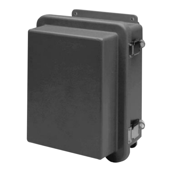
Bosch LTC 8561 Series Instruction Manual
Ltc 8561, 8564/20, 8566 series single channel on-site receiver/drivers
Hide thumbs
Also See for LTC 8561 Series:
- Instruction manual (126 pages) ,
- Instruction manual (104 pages)
Summary of Contents for Bosch LTC 8561 Series
- Page 1 LTC 8561, 8564/20, 8566 Series Instruction Manual EN Single Channel On-site Receiver/Drivers...
-
Page 2: Important Safeguards
9. Safety Check - Upon completion of servicing or repairs to the unit, ask the service technician to perform safety checks to ensure proper operating condition. Bosch Security Systems | January 19, 2006... -
Page 3: Fcc Information
ON-OFF switch is in the ON position. The power cord is the main power disconnect for all units. Bosch Security Systems | January 19, 2006... -
Page 4: Precauciones De Seguridad
Toutefois, las unidades. l'appareil ne fonctionne réellement que lorsque le commutateur est réglé sur ON. Le débranchement du cordon d'alimentation permet de couper l'alimentation des appareils. Bosch Security Systems | January 19, 2006... - Page 5 źródła zasilania; jednak cavo di alimentazione costituisce il dispositivo di scollegamento urządzenie działa tylko wtedy, gdy wyłącznik zasilania jest dell'alimentazione principale per tutte le unità. włączony. Przewód zasilania jest głównym wyłącznikiem zasilania we wszystkich urządzeniach. Bosch Security Systems | January 19, 2006...
-
Page 6: Table Of Contents
ILLUSTRATIONS .............18 Bosch Security Systems | January 19, 2006... -
Page 7: Unpacking
Check for the following items: lenses. These receiver/drivers are used in conjunction ® • LTC 8561 Series, LTC 8564/20, or LTC 8566 Series with the Allegiant Series Microprocessor-based Receiver/Driver. Switcher/Controller Systems. -
Page 8: Installation
If the receiver/driver has been in components are attached to: operation and a switch is changed, the main AC power should be turned off for 10 seconds then turned on to reset the unit. Bosch Security Systems | January 19, 2006... -
Page 9: Lens Speed Table
1. Locate the two 4-position DIP switches on control auto-pan type is selected. See Auto-pan (S102, the top of the printed circuit board. #4). With the switch in the OFF position, auto-pan is Bosch Security Systems | January 19, 2006... -
Page 10: Auto-Pan (S102, #4)
Auxiliary #3 operates as a circuit switch between the number should match the camera number that special ground wire of the zoom lens and the lens you select from the keyboard. motor common terminal (see lens data sheet for Bosch Security Systems | January 19, 2006... -
Page 11: Field Setup
Wire Size 0.5 A Load 1 A Load 1.5 A Load 2 A Load Table is based on a nominal 24 VAC source with a 10% drop in voltage due to cable loss. Bosch Security Systems | January 19, 2006... -
Page 12: Connecting Biphase Signal Cable
1. Connect one wire of the approved type signal cable to terminal 4 of the signal-in terminal block. Note that this color wire is the SIGNAL + for the next device. Bosch Security Systems | January 19, 2006... -
Page 13: Connecting Lens Motor
2. Connect the pan/tilt sensor ground cable to or both may occur. conductor 5 on terminal strip, J111. Bosch Security Systems | January 19, 2006... -
Page 14: Auxiliary Circuits Pin Assignment
This function is used to control the special ground connection of a zoom lens which provides a manual- iris override feature. More information is provided in the S103, #2, Setting Option Switches section of this manual. Bosch Security Systems | January 19, 2006... -
Page 15: Power Up Operation
4. Release push button and repeat steps 2 and 3 if additional tests are desired. 5. Be sure to set the thumbwheel switches back to their original address number so that this device can be properly activated by the system. Bosch Security Systems | January 19, 2006... -
Page 16: Home Position
PC software Four conductor terminal block, J105, is found in the (LTC 0650). middle of the top, main printed circuit board. Pin one is to the left side of the connector. Bosch Security Systems | January 19, 2006... -
Page 17: Pre-Position
Six conductor terminal block, J406, and two conductor COMMON Common contact. terminal block, J401, are found near the left hand side of the lower printed circuit board. Pin one is to the left Normally closed contact. side of connector. Bosch Security Systems | January 19, 2006... -
Page 18: Illustrations
12 VOLT 6 VOLT LENS VOLTAGE FASTEST CAUTION: PAN/TILT MOVEMENT OCCURS UPON INITIAL POWER UP OF RECEIVER/DRIVER! A.C. LINE SOURCE WIRE SIZE #14 AWG MINIMUM This Label Appears Inside the Lid of the Unit. Bosch Security Systems | January 19, 2006... - Page 19 EN | 19 LTC 8561 | Instruction Manual | Illustrations Bosch Security Systems | January 19, 2006...
-
Page 20: Bosch Security Systems | January
+1 800 289 0096 Fax: +31 (0) 40 27 86668 Fax: +65 6319 3499 security.sales@us.bosch.com emea.securitysystems@bosch.com apr.securitysystems@bosch.com http://www.boschsecurity.us http://www.boschsecurity.com http://www.boschsecurity.com © 2006 Bosch Security Systems GmbH 3935 890 06014 06-03 | Updated January 19, 2006 | Data subject to change without notice.


Need help?
Do you have a question about the LTC 8561 Series and is the answer not in the manual?
Questions and answers