Bosch CLIMATE 5000 VRF RDCI Series Installation & User Manual
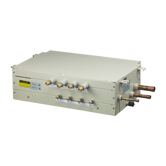
Switch box
Hide thumbs
Also See for CLIMATE 5000 VRF RDCI Series:
- Installation manual (36 pages) ,
- Installation & user manual (24 pages) ,
- Installation and user manual (16 pages)
Table of Contents

Related Manuals for Bosch CLIMATE 5000 VRF RDCI Series


Summary of Contents for Bosch CLIMATE 5000 VRF RDCI Series
- Page 1 CLIMATE 5000 VRF Switch Box (RDCI Series) SBOX01-1, SBOX02-1, SBOX04-1, SBOX06-1, SBOX02E-1, SBOX04E-1 Installation-user manual Before using your air conditioner, please read this manual carefully and keep it for future reference.
-
Page 2: Installation Information
• Ensure only qualified personnel carry out works on this equipment. 4. Ensure the SBOX is installed within the pipe limitations. • Only install manufactured products by Bosch. Do not use other products unless suggested by Bosch. • When installing in a small room, take steps to ensure if a leak happens, the CAUTION room is well ventilated. - Page 3 INSTALLATION INFORMATION | 3 2.2. SBOX Installation and maintenance needed space Ceiling concrete Pipe 0.3m or more hanger Refrigerant 1.5m or less 1.5m or less pipe Do not install the SBOX to close to the ceiling Tex(minimum 50mm) Ceiling tex Fig.2-1 400mm or more 400mm...
- Page 4 4 | SYSTEM WIRING SPECIFICATION SYSTEM WIRING SPECIFICATION Please check the following contents were supplied within the box. If any equipment is missing, ring you local distributor for replacement. ACCESSORIES Table:3-1 NAME QTY. SHAPE Installation & operation For the SBOX installation and manual operation instructions 2-12...
-
Page 5: Dimension Figure
SBOX INSTALLATION | 5 SBOX INSTALLATION 4.3. Dimension Figure WARNING 4.1. Install the main body 4.1.1 Install appropriate fixings. Check the weight of the SBOX. 1. Select a suitable location for the SBOX to be installed. 4.1.2 Hoisting install the SBOX 1. - Page 6 6 | ARRANGEMENTS FOR DRAINAGE PIPE 4.4. Hanging the SBOX CAUTION 1. Adjust the nuts, to ensure the SBOX is level. Make sure a foam gasket us used when tightening the nuts. This will stop vibration noise. See Fig.4-2 Make sure every joint in the drain is sealed using solvent weld. 2.
-
Page 7: Install The Connecting Pipe
INSTALL THE CONNECTING PIPE | 7 INSTALL THE CONNECTING PIPE Connecting diagram 2 6.1. Range of SBOX application Table: 6-1 max: 1 unit, max capacity: 28kW indoor unit SBOX outside Max. connecting Max. total indoor Model drawing indoor unit quantity unit capacity SBOX01 4×1=4... - Page 8 8 | INSTALL THE CONNECTING PIPE 6.3. Pipe size 3) After connecting all the pipe work, ensure you flush the system through with (Unit: mm) nitrogen and pressure test according to outdoor installation manual. 6.4.1 SBOX pipe size Table: 6-3 Model SBOX01 SBOX2 &...
-
Page 9: Pipeline Connection
INSTALL THE CONNECTING PIPE | 9 6.5. Pipeline connection CAUTION 1. Flare 1) Use a pipe cutter to cut off the pipe (See Fig.6-4) 6.6. Welding the copper pipe Use braze-welding for the low pressure gas pipe, high pressure gas pipe, liquid Burr Coarse Slant... - Page 10 10 | WIRING 6.8. Check the Leakage 7.2. Power specification Check all the joints with the leak detector or soap water. Use the table below for power cable selection. 6.9. Thermal insulation Table 7-1 Use appropriate thermal insulation for pipe insulation. Use thicker insulation SBOX Power Item when installing in hot or humid conditions.
- Page 11 WIRING | 11 7.4. Wiring figure of piping lines and signal wires 1.For SBOX01, SBOX02, SBOX04, SBOX06 2# SBOX UNIT (P Q E) 1 2 3 4 5 6 OUTDOOR UNIT 1# SBOX UNIT For SBOX01 1 2 3 4 5 6 For SBOX02 For SBOX0E 1# SBOX UNIT...
-
Page 12: Application Control
12 | APPLICATION CONTROL APPLICATION CONTROL 7.5. Wiring requirements for signal wire 1. You must use shielded wire for communication signal cables. 8.1. Spot check instruction of main control panel SBOX Spot check keys SW1-SW6 are separately corresponded to No.1-6 system 2. -
Page 13: Test Running
TEST RUNNING | 13 TEST RUNNING 9.1. Confirm the following before operation 1. Whether the SBOX, indoor unit and outdoor unit are installed correctly; 2. Whether the tubing and wiring are correctly completed; 3. Whether check the leakage of refrigeration piping system; 4. - Page 14 14 | NOTES NOTES 6720862460 (16/04) CLIMATE 5000 VRF...
- Page 15 NOTES | 15 CLIMATE 5000 VRF 6720862460 (16/04)
- Page 16 Bosch Thermotechnology Ltd. CotswoldWay, Warndon, Worcester WR4 9SW All Enquiries: 0330 123 3004 www.bosch-industrial.co.uk...
Need help?
Do you have a question about the CLIMATE 5000 VRF RDCI Series and is the answer not in the manual?
Questions and answers