Table of Contents
Advertisement
Quick Links
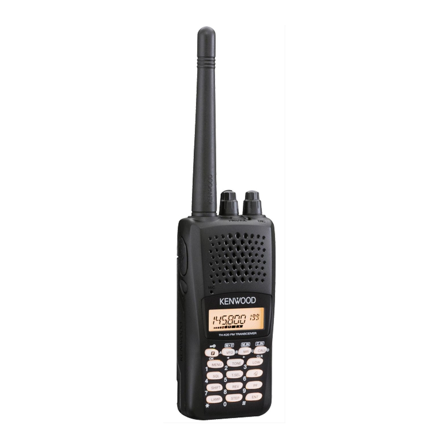
INSTRUCTION MANUAL
144 MHz FM TRANSCEIVER
TH-K20A
TH-K20E
430 MHz FM TRANSCEIVER
TH-K40A
TH-K40E
NOTIFICATION
This equipment complies with the essential requirements of
Directive 1999/5/EC.
The use of the warning symbol
to restrictions of use in certain countries.
This equipment requires a licence and is intended for use in the
countries as below.
AT
BE
DK
IE
IT
SE
CH
GB
LT
MT
PL
© B62-2365-00 (K, E, M)
09 08 07 06 05 04 03 02 01 00
means the equipment is subject
FI
FR
LI
LU
NL
CY
CZ
SK
SI
DE
GR
IS
NO
PT
ES
EE
HU
LV
BG
RO
ISO3166
Advertisement
Table of Contents

Related Manuals for Kenwood TH-K40A


Summary of Contents for Kenwood TH-K40A
-
Page 1: Instruction Manual
INSTRUCTION MANUAL 144 MHz FM TRANSCEIVER TH-K20A TH-K20E 430 MHz FM TRANSCEIVER TH-K40A TH-K40E NOTIFICATION This equipment complies with the essential requirements of Directive 1999/5/EC. The use of the warning symbol means the equipment is subject to restrictions of use in certain countries. -
Page 2: Thank You
Notice: The sign "Pb" below the symbol for batteries indicates that this battery contains lead. Firmware Copyrights The title to and ownership of copyrights for firmware embedded in KENWOOD product memories are reserved for JVC KENWOOD Corporation. WHEN CONDENSATION OCCURS INSIDE THE TRANSCEIVER Condensation may occur inside the transceiver in such a case where the room is warmed using a heater on cold days or where the transceiver is quickly moved from a cold room to a warm room. -
Page 3: Notices To The User
For information on Li-ion battery recycling in your area, call (toll free) 1-800-8-BATTERY (1-800-822-8837). KENWOOD’s involvement in this program is part of our commitment to preserve our environment and conserve our natural resources. This device complies with Industry Canada licence-exempt RSS standard(s). - Page 4 Ensure that there are no metallic items located between the transceiver and the battery pack. • Do not use options not specified by KENWOOD. • If the die-cast chassis or other transceiver part is damaged, do not touch the damaged parts.
- Page 5 • Danger of explosion if the battery is incorrectly replaced; replace only with the same type. • When operating the transceiver in areas where the air is dry, it is easy to build up an electric charge (static electricity). When using an earphone accessory in such conditions, it is possible for the transceiver to send an electric shock through the earphone and to your ear.
- Page 6 • Do not pierce the battery with any object, strike it with an instrument, or step on it! This may break or deform the battery, causing a short-circuit. The battery may generate heat or smoke, rupture, or burst into flame. •...
-
Page 7: Table Of Contents
CONTENTS PREPARATION ....................1 SUPPLIED ACCESSORIES ................1 INSTALLING THE ANTENNA................. 1 INSTALLING THE BATTERY PACK .............. 2 INSTALLING THE BELT CLIP ................ 2 CHARGING THE BATTERY PACK ..............3 CONNECTING TO THE PC................5 GETTING ACQUAINTED ..................6 PANEL ......................6 DISPLAY ...................... - Page 8 OPERATING THROUGH REPEATERS ............31 SELECTING AN OFFSET DIRECTION (SHIFT) .......... 31 SELECTING AN OFFSET FREQUENCY ............. 32 TONE FUNCTION ..................32 AUTOMATIC REPEATER OFFSET ............. 34 REVERSE FUNCTION ................. 34 TRANSMITTING A 1750 Hz TONE .............. 35 SIGNALING ......................36 CTCSS ......................
-
Page 9: Preparation
PREPARATION SUPPLIED ACCESSORIES After carefully unpacking the transceiver, identify the items listed in the table below. We recommend you keep the box and packaging for shipping. Quantity Item Comments K type E type M type Antenna Li-ion battery pack KNB-63L Battery charger with AC adapter (KSC-35S) Belt clip... -
Page 10: Installing The Battery Pack
INSTALLING THE BATTERY PACK Note: Because the battery pack is provided uncharged, you must charge the battery pack before using it with the transceiver. To charge the battery pack, refer to “CHARGING THE BATTERY PACK ” {page 3}. 1 To install the battery pack, align the base of the battery pack with the transceiver, then press Lock lever the battery pack into place until the lock lever is... -
Page 11: Charging The Battery Pack
CHARGING THE BATTERY PACK The battery pack can be charged after it has been installed onto the transceiver. (The battery pack is provided uncharged for safety purposes.) 1 Confirm that the transceiver power is OFF. • While charging the transceiver with a battery pack installed, be sure to turn the transceiver power OFF. -
Page 12: Battery Life
Approximate Charging Times 3 hours Charger Status Table Indicator color Meaning A battery pack is in the charging slot and charging has started. The battery pack is defective or the battery pack Blinking Red contacts are not properly mated with those of the charger. -
Page 13: Connecting To The Pc
COM (serial) ports on your PC. To PC PG-4Y To download the MCP-5A software, go to: http://www.kenwood.com/i/products/info/amateur/software_download.html (This URL may change without notice.) Note: No guarantee is provided for data that may be erased or destroyed due to malfunctions of this unit or your computer. -
Page 14: Getting Acquainted
GETTING ACQUAINTED PANEL Microphone Speaker PWR/VOL control Turn clockwise to switch the transceiver ON. To switch the transceiver OFF, turn counterclockwise until a click sounds. Rotate to adjust the volume level. TX-RX LED Lights red while transmitting and green while receiving a signal. ENC Control Rotate to select an operating frequency, Memory channel, Menu number, and setting value or to change the scan direction, etc. - Page 15 Keypad Use the keypad to perform the following operations. Additionally, you can use the 10-key keypad for direct frequency entry and manually transmitting DTMF tones. Key name Press Operation Ref. page To enter MHz tuning mode. [KEY] To turn the Function ON. [F] - [KEY] To turn the Function OFF.
-
Page 16: Display
Key name Press Operation Ref. page [KEY] To turn the Backlight ON. [LAMP] [F] - [KEY] To keep the Backlight ON continuously. [STEP] [KEY] To enter the Frequency step size setup mode. To enter Direct frequency entry mode. [ENT] [KEY] MIC/ SP Jack Connect the optional Speaker/ Microphone to this jack. - Page 17 Indicator Description Appears when the Shift function is set to plus. Appears when the Shift function is set to minus. Appears when the Shift function is set to –7.6 MHz. (TH-K40E (E type) only) Displays the operating frequency, setting information, etc. Displays the Memory channel number.
-
Page 18: Basic Operation
BASIC OPERATION SWITCHING THE POWER ON/OFF Turn the PWR/VOL control clockwise to switch the transceiver ON. • The power on message momentarily appears on the display. Turn the PWR/VOL control counterclockwise to switch the transceiver OFF. ADJUSTING THE VOLUME Rotate the PWR/VOL control to adjust the volume. Clockwise increases the volume and counterclockwise decreases it. -
Page 19: Selecting A Frequency
SELECTING A FREQUENCY VFO MODE This is the basic mode for changing the operating frequency. Rotate the ENC control clockwise to increase the frequency and counterclockwise to decrease the frequency. MHz TUNING MODE If the desired operating frequency is far away from the current frequency, it is quicker to use the MHz Tuning Mode. -
Page 20: Direct Frequency Entry
DIRECT FREQUENCY ENTRY In addition to rotating the ENC control, there is another way to select the frequency. When the desired frequency is far away from the current frequency, you can directly enter a frequency using the numeric keypad. 1 Press [VFO]. •... -
Page 21: Backlight
REMAINING BATTERY CAPACITY You can confirm the remaining battery capacity when you transmit in low power. To check the remaining capacity: • The bar-graph shows the remaining battery capacity. High battery power Low battery power or no display : Recharge or replace the batteries. Note: You may not be able to transmit at high power if the battery remaining indicator shows low battery power. -
Page 22: Lock Function
LOCK FUNCTION The lock function disables most of the keys to prevent you from accidentally activating a function. 1 Press [F] (1s) to turn the Lock function ON. • The “ ” icon appears when the Lock function is ON. •... -
Page 23: Menu Setup
MENU SETUP WHAT IS A MENU? Many functions on this transceiver are selected or configured via a software- controlled Menu rather than through the physical controls of the transceiver. Once you become familiar with the Menu system, you will appreciate its versatility. -
Page 24: Menu Function List
SAVE (sec) Automatic Power- OFF/ 30/ 60/ 90/ 120/ 30 (min) 180 (min) TH-K20A/E: Programmable 136 ~ 173 MHz P.VFO TH-K40A/E: It differs 400 ~ 469 MHz between the Repeater Offset model and 0.000 ~ 29.950 (MHz) OFFSET Frequency type. - Page 25 Ref. Display Description Setting Values Default Setting Page TX inhibit OFF/ ON TX.INH Microphone HIGH/ MEDIUM/ LOW MEDIUM M.SENS Sensitivity It differs 1750/ WX/ N.FM/ between the Panel PF key PF KEY PR.SCAN/ M.DISP model and type. Microphone PF 1 VFO/ MR/ CALL/ UP/ PF 1 DOWN/ TONE/ T.SEL/...
-
Page 26: Memory Channels
MEMORY CHANNELS In Memory channels, you can store frequencies and related data that you often use. Then you need not reprogram the data every time. You can quickly recall a programmed channel by simple operation. A total of 200 Memory channels are available. -
Page 27: Storing Simplex And Standard Repeater Frequencies
Simplex & Parameter Odd-split Repeater Memory channel lockout * Narrow FM Beat shift * Program Scan Memory and the Priority channel cannot be stored as ON or OFF for Memory channel lockout. STORING SIMPLEX AND STANDARD REPEATER FREQUENCIES 1 Press [VFO] to enter VFO mode. 2 Rotate the ENC control to select your desired frequency. -
Page 28: Storing Odd-Split Repeater Frequencies
STORING ODD-SPLIT REPEATER FREQUENCIES Some repeaters use a receive/transmit frequency pair with a non-standard offset. If you store two separate frequencies in a memory channel, you can operate on those repeaters without programming the offset frequency and direction. 1 Store the desired receiving frequency and related data by following the procedure given for simplex or standard repeater frequencies. -
Page 29: Naming A Memory Channel
Note: ◆ You cannot recall an empty memory channel. An error beep sounds. ◆ You cannot recall the Program Scan memory channels (L0/U0 ~ L2/U2) or Priority Channel (Pr) using the numeric keypad. ◆ When recalling an odd-split memory channel, “ ”... -
Page 30: Memory Display Type
MEMORY DISPLAY TYPE After storing a Memory name, the Memory name appears in place of the operating frequency. However, you can still display the operating frequency, if desired. To display the frequency rather than Memory name, access Menu No. 12 (M.DISP) and select “FREQ”. This menu toggles the display mode between the Memory name (“NAME”) and frequency display (“FREQ”). -
Page 31: Call Channel
In this case, Call Scan will be useful. The default Call Channel frequency is 144.000 MHz (TH-K20A/E)/ 430.000 MHz (TH-K40A/E). Note: Unlike memory channels 0 to 199, the Call Channel cannot be cleared. RECALLING THE CALL CHANNEL Press [CALL] to recall the Call Channel. -
Page 32: Memory Channel Transfer
MEMORY CHANNEL TRANSFER MEMORY TO VFO TRANSFER After retrieving frequencies and associated data from Memory Recall mode, you can copy the data to the VFO. This function is useful, for example, when the frequency you want to monitor is near the frequency stored in a memory channel. 1 Press [MR], then turn the ENC control to recall a desired memory channel. - Page 33 Note: ◆ To enter the Channel Display Mode, you must have at least one memory channel that contains the data. ◆ If the memory channel contains the Memory name data, the Memory name is displayed in place of the “CH” characters. ◆...
-
Page 34: Scan
SCAN Scan is a useful feature for hands-off monitoring of your favorite frequencies. Becoming comfortable with all types of Scan will increase your operating efficiency. This transceiver provides the following type of scans: Band Scan Scans all frequencies on the current band. Scans the specified frequency ranges stored in Memory Program Scan channels L0/U0 ~ L2/U2. -
Page 35: Program Scan
PROGRAM SCAN You can limit the scanning frequency range. There are 3 memory channel pairs (L0/U0 ~ L2/U2) available for specifying the start and end frequencies. Program Scan monitors the range between the start and end frequencies that you have stored in these memory channels. -
Page 36: Memory Scan
MEMORY SCAN 1 Press [MR] (1s). • Scan starts from the last memory channel number and ascends up through the channel numbers (default). • Rotate the ENC control to change the scanning direction. 2 To stop Memory Scan, press any key other than [MONI], [LAMP], [F], [SQL], [F] (1s), or [F] - [LAMP]. -
Page 37: Memory Channel Lockout
5 Press [MR] to store the data on the Priority Channel. USING PRIORITY SCAN 1 Enter Menu mode and access Menu No. 15 (PR.SCAN), then press [F]. 2 Rotate the ENC control to select “ON” to store the setting. , then press [F] 3 Press [MENU] or [PTT] to exit Menu mode. -
Page 38: Selecting A Scan Resume Method
SELECTING A SCAN RESUME METHOD The transceiver stops scanning at a frequency or Memory channel on which a signal is detected. It then continues scanning according to which resume mode you have selected. You can choose one of the following modes. The default is Time-operated mode. -
Page 39: Operating Through Repeaters
OPERATING THROUGH REPEATERS Repeaters are often installed and maintained by radio clubs, sometimes with the cooperation of local businesses involved in the communications industry. Compared to simplex communication, you can usually transmit over much greater distances by using a repeater. Repeaters are typically located on mountain tops or other elevated locations. -
Page 40: Selecting An Offset Frequency
SELECTING AN OFFSET FREQUENCY To access a repeater which requires an odd-split frequency pair, change the offset frequency from the default which is used by most repeaters. 1 Enter Menu mode and access Menu No. 7 (OFFSET). 2 Rotate the ENC control to select the appropriate offset frequency value. •... - Page 41 Available Tone Frequencies Tone Frequency (Hz) 67.0 82.5 100.0 123.0 151.4 186.2 225.7 69.3 85.4 103.5 127.3 156.7 192.8 229.1 71.9 88.5 107.2 131.8 162.2 203.5 233.6 74.4 91.5 110.9 136.5 167.9 206.5 241.8 77.0 94.8 114.8 141.3 173.8 210.7 250.3 79.7 97.4...
-
Page 42: Automatic Repeater Offset
– offset 148.000 MHz and higher No offset Note: Even when setting the TH-K20A/ TH-K40A M type and TH-K40E (E type) model to “ON”, the ARO function will not operate. REVERSE FUNCTION After setting a separate receive and transmit frequency, you can exchange these frequencies using the Reverse function. -
Page 43: Transmitting A 1750 Hz Tone
Note: ◆ If the transmit frequency is outside the allowable transmit frequency range when using Reverse, pressing [PTT] will cause an error tone to sound and transmitting will be inhibited. ◆ If the receiving frequency is outside the receiving frequency range when using Reverse, an error tone will sound and Reverse will not operate. -
Page 44: Signaling
SIGNALING CTCSS You may sometimes want to hear calls only from specific persons. The Continuous Tone Coded Squelch System (CTCSS) allows you to ignore (not hear) unwanted calls from other persons who are using the same frequency. To do so, select the same CTCSS tone as selected by the other persons in your group. -
Page 45: Dcs
CTCSS FREQUENCY SCAN This function scans through all CTCSS frequencies to identify the incoming CTCSS frequency on a received signal. You can use this function to find which CTCSS frequency is used by your group. 1 Press [TONE] 2 times to turn the CTCSS function ON. •... - Page 46 USING DCS 1 Press [TONE] 3 times to activate the DCS function. • Each time you press [TONE], the selection changes as follows: ➡ ➡ ➡ ➡ Tone ( CTCSS ( DCS ( Cross Tone ( ) Off (no display). •...
-
Page 47: Cross Tone
CROSS TONE You can set separate signaling types by TX and RX for when you access a repeater that uses different encode/ decode signaling. 1 Press [TONE] 4 times to activate the Cross Tone function. • Each time you press [TONE], the selection changes as follows: ➡... -
Page 48: Dtmf Functions
DTMF FUNCTIONS This transceiver provides you with 16 dedicated DTMF memory channels. You can store a DTMF code (16 digits max.) in each of these channels to recall later for speed dialing. MANUAL DIALING The numeric keypad functions as a DTMF keypad; the 12 keys found on a touch- tone phone plus 4 additional keys (A, B, C, D) on the right most column. -
Page 49: Adjusting The Dtmf Code Transmit Speed
• You can move the cursor to the left or right by pressing [VFO] or [MR]. • Press [CALL] to delete the character at the current cursor position. • On the transceiver display, DTMF code “ ” is represented by “E” and “#” is represented by “F”. -
Page 50: Dtmf Tx Hold
DTMF TX HOLD This function causes the transceiver to remain in transmit mode for 2 seconds after you release each key. Therefore, you can release [PTT] while sending DTMF tones through manual dialing. 1 Enter Menu mode and access Menu No. 30 (DT.HOLD), then press [F]. 2 Rotate the ENC control to select “ON”, then press [F] to store the setting. -
Page 51: Auxiliary Functions
AUXILIARY FUNCTIONS PROGRAMMABLE VFO If you want to limit the operating frequencies within a certain range, program the lower and upper frequency limits to the programmable VFO parameters. For example, if you select 144 MHz for the lower limit and 145 MHz for the upper limit, the tunable range will be limited from 144.000 MHz to 145.995 MHz. -
Page 52: Frequency Step Size
FREQUENCY STEP SIZE Choosing the correct frequency step size is essential in order to select your exact receive frequency using the ENC control. You can select your desired frequency step size from: 5, 6.25, 10, 12.5, 15, 20, 25, 30, 50, or 100 (kHz). To change the frequency step size: 1 Press [STEP]. -
Page 53: Power On Message
Note: ◆ While Tone Alert is ON, there is no speaker output when a signal is received. To monitor the signal, press and hold [MONI]. ◆ When Tone Alert is ON, APO does not turn the power OFF. ◆ If you switch the transceiver OFF while the “ ”... -
Page 54: Beep Function
BEEP FUNCTION The Beep function provides confirmation of entry, error status, and malfunctions of the transceiver. We recommend you leave this function ON in order to detect erroneous operations and malfunctions. However, to turn the beep function OFF: 1 Enter Menu mode and access Menu No. 2 (BEEP), then press [F]. 2 Rotate the ENC control to select “OFF”, then press [F] to store the setting. -
Page 55: Battery Saver
“KEY.FRQ”: Only the following keys can be operated. PWR/VOL control MONI LAMP BATTERY SAVER The Battery Saver extends the operating time of the transceiver. It automatically activates when the squelch is closed and no key is pressed for more than 10 seconds. To reduce battery consumption, this function shuts the receiver circuit OFF for the programmed time, then momentarily turn it back ON to detect a signal. -
Page 56: Apo (Auto Power Off)
APO (AUTO POWER OFF) The transceiver switches OFF automatically if no keys or controls are pressed or adjusted for 30 minutes (default). One minute before the transceiver switches OFF, warning beeps sound for a few seconds and “APO” blinks. You can select the APO time from OFF (disable), 30 (default), 60, 90, 120, or 180 minutes. -
Page 57: Beat Shift
BEAT SHIFT Since the transceiver uses a microprocessor to control various functions of the transceiver, the CPU clock oscillator’s harmonics or image may appear on some spots of the receive frequencies. In this case, turn the Beat Shift function ON. 1 Enter Menu mode and access Menu No. - Page 58 VOX GAIN To enjoy the VOX function, take the time to properly adjust the VOX Gain level. This level controls the VOX circuit to detect the presence or absence of your voice. There are 2 ways to adjust the VOX Gain. While the VOX function is ON: 1 Speak into the headset microphone using your normal tone of voice to transmit.
-
Page 59: Time-Out Timer
2 Rotate the ENC control to select the desired delay time to 250/ 500 (default)/ 750/ 1000/ 1500/ 2000/ 3000 ms, then press [F] to store the setting. 3 Press [MENU] or [PTT] to exit Menu mode. Note: ◆ If you press [PTT] while the VOX function is ON, the VOX Delay Time is not reflected to the transmitted signal. -
Page 60: Tx Inhibit
Programmable functions available are: M.DISP (Memory display type)/ 1750/ WX <TH-K20A K type only>/ N.FM/ PR.SCAN (Priority scan). Default setting: TH-K20A K type: WX, TH-K20A/ TH-K40A M type: M.DISP TH-K20E/ TH-K40E (E type): 1750 3 Press [MENU] or [PTT] to exit Menu mode. -
Page 61: Microphone Key Lock
MICROPHONE PF KEYS There are 3 microphone PF (Programmable Function) keys: [PF1], [PF2], and [PF3]. You can assign your desired functions to these 3 keys. 1 Enter Menu mode and access Menu No. 24 (PF 1) and/or Menu No. 25 (PF 2) and/or Menu No. -
Page 62: Weather Alert (Th-K20A K Type Only)
WEATHER ALERT (TH-K20A K TYPE ONLY) Weather Alert is available only in the USA and Canada. When activated, this function will check for a received NOAA 1050 Hz tone. When the tone is received, the weather alert tone will sound. WEATHER ALERT ON/ OFF 1 Enter Menu mode and access Menu No. -
Page 63: Appendix
SERVICE: When returning this product for repair, send the complete product, packed in its original box and packing material, to the authorized KENWOOD dealer from whom you purchased it, or any authorized KENWOOD service center. Include a full description of the problem(s) experienced. -
Page 64: Troubleshooting
Note: ◆ Record the date of purchase, serial number and dealer from whom this product was purchased. ◆ For your own information, retain a written record of any maintenance performed on this product. ◆ When claiming warranty service, please include a photocopy of the bill of sale or other proof-of-purchase showing the date of sale. - Page 65 However, the following Internal Beat Frequencies cannot be eliminated. TH-K20A/E: 152.69375/ 152.695/ 152.7/ 152.705/152.70625/ 153.59375/ 153.595/ 153.6/ 153.605/ 153.60625/ 172.79375/ 172.795/ 172.8/ 172.805/ 172.80625 (MHz) TH-K40A/E: 403.19375/ 403.195/ 403.2/ 403.205/ 403.20625/ 422.39375/ 422.395/ 422.4/ 422.405/ 422.40625/ 441.59375/ 441.595/ 441.6/ 441.605/ 441.60625/ 460.79375/ 460.795/ 460.8/ 460.805/ 460.80625 (MHz)
-
Page 66: Transceiver Reset
TRANSCEIVER RESET There are 2 types of transceiver resets available: Partial Reset Use to initialize all settings other than the Memory channels and DTMF memory channels. Full Reset Use to initialize all transceiver settings that you have customized. There are 2 ways to perform a reset on the transceiver: by key operation and by accessing Menu mode. -
Page 67: Specifications
SPECIFICATIONS Note: All specifications are guaranteed within the amateur radio band. General TH-K20A/E TH-K40A/E 144 ~ 148 (K/M) Guaranteed range (MHz) TX & RX 430 ~ 440 144 ~ 146 (E) 136 ~ 174 (M) 400 ~ 470 (M) 144 ~ 148 (K)
Need help?
Do you have a question about the TH-K40A and is the answer not in the manual?
Questions and answers