Table of Contents
Advertisement
144MHz FM TRANSCEIVER
TH-K2AT/K2E/K2ET
SERVICE MANUAL
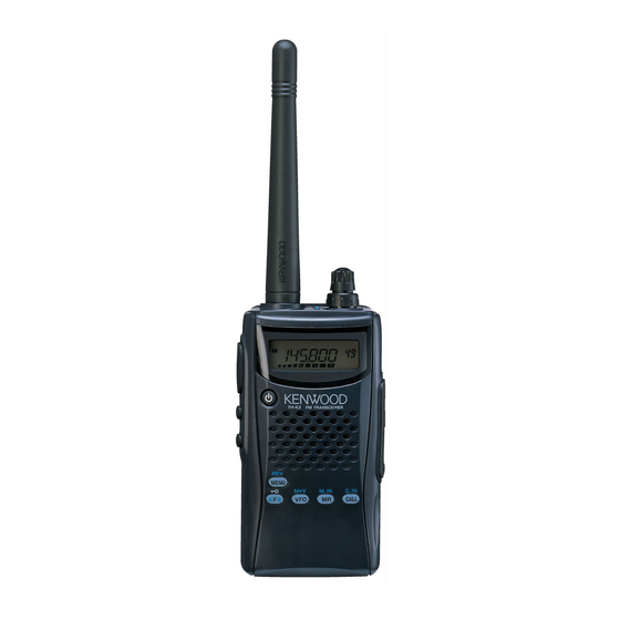
Helical Antenna
(T90-1018-25)
Knob
(PTT/LAMP/MON)
(K29-9274-03)
Key top (16key)
(K29-9272-02)
TH-K2AT/K2ET
DISASSEMBLY FOR REPAIR ................................... 2
CIRCUIT DESCRIPTION ............................................ 6
SEMICONDUCTOR DATA ...................................... 14
COMPONENTS DESCRIPTION .............................. 15
PARTS LIST ............................................................. 17
EXPLODED VIEW .................................................... 23
PACKING ................................................................. 25
ADJUSTMENT ........................................................ 27
TERMINAL FUNCTION ........................................... 43
PC BOARD
TX-RX UNIT (X57-674X-XX) (A/3) ................... 44
TX-RX UNIT (X57-674X-XX) (B/3),(C/3) .......... 48
Knob (ENC)
(K29-5159-03)
Knob (VOL)
(K29-5150-03)
Front glass
(B10-2746-03)
Cap
(SP/MIC/DC IN)
(B09-0675-03)
Cabinet assy
(16key)
(A02-3819-23)
CONTENTS
©
2003-8 PRINTED IN JAPAN
B51-8658-00 (S) 836
Helical Antenna
(T90-1018-25)
Knob
(PTT/LAMP/MON)
(K29-9274-03)
Key top (4key)
(K29-9276-02)
TH-K2E
SCHEMATIC DIAGRAM .......................................... 50
LEVEL DIAGRAM .................................................... 55
BLOCK DIAGRAM ................................................... 56
BC-21 (WALL CHARGER) ....................................... 58
PB-43N (Ni-MH BATTERY PACK) .......................... 58
BT-14 (BATTERY CASE) ......................................... 59
PG-4Y (PROGRAMMING INTERFACE CABLE) ..... 59
MCP-1A (MEMORY CONTROL PROGRAM) ......... 59
SPECIFICATIONS ................................. BACK COVER
Knob (ENC)
(K29-5159-03)
Knob (VOL)
(K29-5150-03)
Front glass
(B10-2746-03)
Cap
(SP/MIC/DC IN)
(B09-0675-03)
Cabinet assy
(4key)
(A02-3818-23)
Advertisement
Table of Contents

Related Manuals for Kenwood 144MHz FM TRANSCEIVER K2E


Summary of Contents for Kenwood 144MHz FM TRANSCEIVER K2E
-
Page 1: Table Of Contents
144MHz FM TRANSCEIVER TH-K2AT/K2E/K2ET SERVICE MANUAL © 2003-8 PRINTED IN JAPAN B51-8658-00 (S) 836 Helical Antenna Helical Antenna (T90-1018-25) (T90-1018-25) Knob (ENC) Knob (ENC) (K29-5159-03) (K29-5159-03) Knob (VOL) Knob (VOL) (K29-5150-03) (K29-5150-03) Front glass Front glass (B10-2746-03) (B10-2746-03) Knob Knob (PTT/LAMP/MON) (PTT/LAMP/MON) (K29-9274-03) -
Page 2: Disassembly For Repair
TH-K2AT/K2E/K2ET DISASSEMBLY FOR REPAIR How to remove the case assembly from the chassis 1. Remove two screws ( ) holding the chassis. 2. Pull out two knobs ( ) and remove two round nuts ( 3. Pull out the SP and MIC parts of the cap from jacks ( 4. - Page 3 TH-K2AT/K2E/K2ET DISASSEMBLY FOR REPAIR Soldering the antenna terminal 4. Apply the tips of soldering irons to all the four pins of the final FET at the same time ( ), heat them sufficiently, and remove 1. With the shield cover removed from the antenna terminal the final FET ( ).
- Page 4 TH-K2AT/K2E/K2ET DISASSEMBLY FOR REPAIR Special care and attention required for assembly (2) By pressing the LCD hardware fixture from the component side of the TX-RX PCB, you must bent all 4 tabs of the LCD 1. Gluing to the key top (MIC element section) hardware fixture being visible from the foil side until the You must also glue on the speaker storage area and heap bases of each tabs are folded at least 45 degrees (Fig.
-
Page 5: Disassembly For Repair
TH-K2AT/K2E/K2ET DISASSEMBLY FOR REPAIR 4. Packing (G53-1572-02) TX/BUSY lamp installation 6. Cautions for installing the chassis on the case assembly procedure (1) Verify that the packing (G53-1572-02) TX/BUSY lamp section (1) To assure waterproofing, install the packing in the chassis is has been past through the hole in the illumination guide groove as shown in Fig. -
Page 6: Circuit Description
TH-K2AT/K2E/K2ET CIRCUIT DESCRIPTION Frequency Configuration A tuning voltage corresponding to the desired signal is applied to each varicap through the BPF/APC terminal (pin 6) The frequency configuration is shown in Figure 1 and of the MPU (IC8) to tune to the receive frequency. Table 1. - Page 7 TH-K2AT/K2E/K2ET CIRCUIT DESCRIPTION IF Circuit FM IC and band-pass filter consisting of R125, R126, R135, The first IF signal (38.85 MHz) amplified by the IF amplifier (Q24) C173, C174. The noise component is rectified in the FM IC to and the second IF signal (38.4 MHz) generated by tripling the 12.8 produce a DC voltage, which is output from the N-REC terminal MHz reference oscillator frequency of the TCXO (X1) by Q23, are (pin 14) of the FM IC as squelch voltage.
- Page 8 TH-K2AT/K2E/K2ET CIRCUIT DESCRIPTION Transmitter System The transmission/reception switching circuit consists of D10, L19, D12 and D13. These diodes are turned ON in transmit Microphone Amplifier Circuit mode and OFF in receive mode to switch signals. The audio signal from the microphone passes through a high-pass filter (IC5) and enters a microphone amplifier (IC16).
- Page 9 TH-K2AT/K2E/K2ET CIRCUIT DESCRIPTION The APC voltage controls the gate voltage of Q11 and Q12, amplifying VCO output with an RF amplifier (Q6) and dividing and keeps transmission output stable. it with the PLL IC. The MPU detects power supply voltage and controls Q58 The PLL synthesizer with 5 kHz and 6.25 kHz step is by transmission power supply voltage and transmission power.
- Page 10 TH-K2AT/K2E/K2ET CIRCUIT DESCRIPTION Power Supply Circuit Power Supply Switching Circuit The voltage supplied through the battery terminal or DC IN Charging Circuit terminal is branched in the power supply switching circuit as When an external power supply is connected to the DC IN shown in Fig.10 and then supplied to the required components.
- Page 11 TH-K2AT/K2E/K2ET CIRCUIT DESCRIPTION Voltage Detection Circuit LED Drive Circuit Various voltages are input to the A/D port of the MPU (IC8) The LCD and key illumination LEDs are lighted by controlling for processing. Q51 for the LCD and Q50 for keys according to the output Battery voltage is divided with resistors (R240, R241) and voltage from the AF/LAMP AVR (Q37).
- Page 12 TH-K2AT/K2E/K2ET CIRCUIT DESCRIPTION Key and Encoder Input Circuit The POWER key is assigned to the interrupt port (pin 95) of Other keys composes a matrix and key presses are detected the MPU. by scanning them by software. The PTT key is assigned to the dedicated port (pins 13, 14) The encoder reads data using the interrupt port (pins 35 of the MPU.
- Page 13 TH-K2AT/K2E/K2ET CIRCUIT DESCRIPTION CTCSS/DCS DTMF The encode signal is generated by the MPU (IC8) and output The DTMF signal is generated by the MPU (IC8) and is from the TONE terminal (pin 41) of the MPU. output from the DTMF/BEEP terminal (pin 40) of the MPU. The unwanted high-frequency components of the encode The DTMF signal is mixed with an audio signal at the input signal output from the MPU are removed with a low-pass filter,...
-
Page 14: Semiconductor Data
TH-K2AT/K2E/K2ET SEMICONDUCTOR DATA MPU : 90522BPFFG139 (IC8) Pin function Function Function Name Name CLOCK Common serial clock output Noise voltage input for squelch (A/D) DATA Common serial data output RSSI voltage input for S-meter (A/D) EEPDI Data input from EEPROM VOXIN Microphone voltage input for VOX (A/D) THERM... -
Page 15: Components Description
TH-K2AT/K2E/K2ET SEMICONDUCTOR DATA / COMPONENTS DESCRIPTION COMPONENTS DESCRIPTION Function Name TX-RX UNIT (X57-674X-XX) DC IN detection interrupt input ( ↓ ) DCDET L:DC IN connected Ref. No. Use/Function Operation/Condition/Compatibility RXLED Busy LED output H:ON PLL IC 100 BSFT Beat shift swiching output H:ON APC differential 101 PLLEN... - Page 16 TH-K2AT/K2E/K2ET COMPONENTS DESCRIPTION Ref. No. Use/Function Operation/Condition/Compatibility Ref. No. Use/Function Operation/Condition/Compatibility Q33 operation Reverse current On when charging Battery switch prevention DC IN detection H: DC IN detection Ni-MH temperature On when temperature detection is constant-voltage detection activated Reverse current Battery AF amplifier/ prevention...
-
Page 17: Parts List
TH-K2AT/K2E/K2ET PARTS LIST ∗ New Parts. indicates safety critical components. L: Scandinavia K: USA P: Canada Parts without Parts No. are not supplied. Y: PX (Far East, Hawaii) T: England E: Europe Les articles non mentionnes dans le Parts No. ne sont pas fournis. Y: AAFES (Europe) X: Australia M: Other Areas... - Page 18 TH-K2AT/K2E/K2ET PARTS LIST TX-RX UNIT (X57-674X-XX) Ref. No. Address Parts No. Description Destination Ref. No. Address Parts No. Description Destination parts parts C92-0002-05 CHIP-TAN 0.22UF 35WV C136 CC73HCH1H100D CHIP C 10PF C92-0714-05 TANTALUM 4.7UF 6.3WV C137 CC73HCH1H050C CHIP C 5.0PF C92-0001-05 CHIP-C 0.1UF...
- Page 19 TH-K2AT/K2E/K2ET PARTS LIST TX-RX UNIT (X57-674X-XX) Ref. No. Address Parts No. Description Destination Ref. No. Address Parts No. Description Destination parts parts C230 CK73FB1C105K CHIP C 1.0UF C359,360 CK73HB1A104K CHIP C 0.10UF K C231,232 CK73HB1H102K CHIP C 1000PF K C366 ∗...
-
Page 20: Parts List
TH-K2AT/K2E/K2ET PARTS LIST TX-RX UNIT (X57-674X-XX) Ref. No. Address Parts No. Description Destination Ref. No. Address Parts No. Description Destination parts parts L41-1078-14 SMALL FIXED INDUCTOR R70-72 RK73EB2ER39K CHIP R 0.39 K 1/4W ∗ L41-2278-14 SMALL FIXED INDUCTOR R74,75 RK73HH1J104D RESISTOR 100K D 1/16W... - Page 21 TH-K2AT/K2E/K2ET PARTS LIST TX-RX UNIT (X57-674X-XX) Ref. No. Address Parts No. Description Destination Ref. No. Address Parts No. Description Destination parts parts R160 RK73HB1J472J CHIP R 4.7K J 1/16W R231 RK73HB1J151J CHIP R J 1/16W R161 RK73HB1J102J CHIP R 1.0K J 1/16W R235,236 RK73HB1J102J...
- Page 22 TH-K2AT/K2E/K2ET PARTS LIST TX-RX UNIT (X57-674X-XX) Ref. No. Address Parts No. Description Destination Ref. No. Address Parts No. Description Destination parts parts MIC1 T91-0580-05 MIC ELEMENT 2SK1215(E) 2SK1830 D1,2 1SV325 VARIABLE CAPACITANCE DIODE 2SC4617(R) TRANSISTOR HSC277 DIODE ∗ RN2105 TRANSISTOR 1SV305 VARIABLE CAPACITANCE DIODE KTC4082...
-
Page 23: Exploded View
TH-K2AT/K2E/K2ET EXPLODED VIEW (TH-K2AT / K2ET) TX-RX Unit (B/3) TX-RX Unit (C/3) TX-RX Unit (A/3) 702. STANDARD LABEL : K, K2 701. STICKER A : N09-1492-05 B : N14-0569-04 C : N14-0573-04 D : N79-2035-46 1 (K2, M2) E : N79-2040-45 F : N82-2007-46 G : N09-2433-05 Parts with the exploded numbers larger than 700 are not supplied. - Page 24 TH-K2AT/K2E/K2ET EXPLODED VIEW (TH-K2E) TX-RX Unit (B/3) TX-RX Unit (C/3) TX-RX Unit (A/3) 701. STICKER A : N09-1492-05 B : N14-0569-04 C : N14-0573-04 D : N79-2035-46 E : N79-2040-45 F : N82-2007-46 G : N09-2433-05 Parts with the exploded numbers larger than 700 are not supplied.
-
Page 25: Packing
TH-K2AT/K2E/K2ET PACKING (K, M, E and E3 types) 703. PAMPHLET (R & TTE) : E, E3 704. PAMPHLET 705. WARRANTY CARD : K, E, E3 11.INSTRUCTION MANUAL (B62-1696-00) (B62-1697-00):K,E,E3 (B62-1699-00):E,E3 41.HELICAL ANTENNA (B62-1702-00):E,E3 (T90-1018-25) 42.CHARGER (230V/13.8V) (B62-1757-00):E,E3 (W08-0959-15) : M, E, E3 (B62-1758-00):E,E3 43.CHARGER (120V/13.8V) (W08-0960-15) : K... - Page 26 TH-K2AT/K2E/K2ET PACKING (K2 and M2 types) 11.INSTRUCTION MANUAL (B62-1695-00):M2 (B62-1696-00) (B62-1697-00):K2 704. PAMPHLET 705. WARRANTY CARD : K2 1.CABINET ASSY 32.HANDSTRAP (BATTERY CASE) (J69-0342-05) : M2 (A02-3817-02) 25.ITEM CARTON CASE (H52-2009-02) 41.HELICAL ANTENNA (T90-1018-25) 30.BELT HOOK ASSY (J29-0709-04) 27.PACKING FIXTURE (H12-3147-03) Parts with the exploded numbers larger than 700 are not supplied.
-
Page 27: Adjustment
TH-K2AT/K2E/K2ET ADJUSTMENT Single Tone Mode G. 7.5V TX M power (Lower limit frequency, center frequency, upper limit frequency) This mode is used to check the DTMF deviation. H. 7.5V TX L power (Lower limit frequency, center frequency, upper limit frequency) Operation I. - Page 28 TH-K2AT/K2E/K2ET ADJUSTMENT Key name [key] [F] key → [key] Transmit while this key is held down. Selecting a TX power (High/Mid/Low) Changes adjustment items. (Forward) LAMP Lamp always ON When this key is pressed on the frequency display, it switches to the adjustment display. Changes adjustment items.
- Page 29 TH-K2AT/K2E/K2ET ADJUSTMENT D. S-meter (Two segments in S-meter light, all segments 2RX BPF (Center frequency) in S-meter light) (1) Press the [LAMP] or [MONI] key on the transceiver to display 1S-meter (Two segments in S-meter light) “BPC” on the LCD. (1) Press the [LAMP] or [MONI] key on the transceiver to display “S1”...
- Page 30 TH-K2AT/K2E/K2ET ADJUSTMENT (8) Press the [MENU] key to write the current APC value into (5) Press the [PTT] key to enable the transmit mode. the EEPROM. (6) Adjust the output voltage from DC power supply until the voltage at the battery terminal becomes 7.5V while the 27.5V TX H power (Center frequency) transceiver is transmitting.
- Page 31 TH-K2AT/K2E/K2ET ADJUSTMENT (2) Press the [VFO], [MR] or [CALL] key to switch to the The current APC value is displayed at the lower digits of frequency display. the frequency display, and the value stored in the EEPROM (3) Turn the encoder to display the lower limit frequency on is displayed on the memory channel number display.
- Page 32 TH-K2AT/K2E/K2ET ADJUSTMENT J. 13.8V TX M power (Lower limit frequency, center (4) Repeat steps (4) to (7) of “113.8V TX M power (Lower frequency, upper limit frequency) limit frequency)” described on page 32. 113.8V TX M power (Lower limit frequency) (1) Press the [LAMP] or [MONI] key on the transceiver to display K.
- Page 33 TH-K2AT/K2E/K2ET ADJUSTMENT 2Tone deviation (Center frequency) (2) Press the [VFO], [MR] or [CALL] key to switch to the frequency display. (1) Press the [LAMP] or [MONI] key on the transceiver to display (3) Turn the encoder to display the upper limit frequency on “DVC”...
- Page 34 TH-K2AT/K2E/K2ET ADJUSTMENT (4) Press the [CALL] key to switch to the adjustment display. (2) Input a specified AG signal to microphone input. (5) When the [PTT] key is pressed to enable transmit mode, a (3) Press the [MENU] key to write the current microphone input preset DCS code (023) is internally generated and level value into the EEPROM.
- Page 35 TH-K2AT/K2E/K2ET ADJUSTMENT Common Section Measurement Adjustment Specifications/ Item Condition Remarks Test equipment Unit Terminal Unit Parts Method 1.Setting and Connect the optional PG-2W LCD total illumination display Initial configuration displayed after resetting DC cable to the power supply. the full-reset. DC IN terminal voltage: 13.8V 1) Total illumination display confirmation...
-
Page 36: Receiver Section
TH-K2AT/K2E/K2ET ADJUSTMENT Receiver section Measurement Adjustment Specifications/ Item Condition Remarks Test equipment Unit Terminal Unit Parts Method 1.RX BPF Squelch level: 0 Adjust 1) Frequency: 145.050MHz TX-RX Turn the VOL knob 0.63V (E, E3) Oscilloscope (A/3) knob to obtain 0.63V AF Frequency: 146.050MHz Distortion meter output. - Page 37 TH-K2AT/K2E/K2ET ADJUSTMENT Measurement Adjustment Specifications/ Item Condition Remarks Test equipment Unit Terminal Unit Parts Method Switch to Adjustment mode and carry out the operations for adjustment item D. (Refer to page 29) S-meter 3) LCD display: S1 TX-RX [MENU] Write Frequency: 145.050MHz (A/3) (E, E3)
- Page 38 TH-K2AT/K2E/K2ET ADJUSTMENT Measurement Adjustment Specifications/ Item Condition Remarks Test equipment Unit Terminal Unit Parts Method 8.AF output 1) Frequency: 145.050MHz TX-RX Check 400mW or more Check (E, E3) Oscilloscope (A/3) Frequency: 146.050MHz Distortion meter (K, K2, M, M2) AF V.M SSG output: –53dBm (501uV) SSG MOD: 1kHz SSG DEV: 3kHz...
- Page 39 TH-K2AT/K2E/K2ET ADJUSTMENT Measurement Adjustment Specifications/ Item Condition Remarks Test equipment Unit Terminal Unit Parts Method 6) LCD display: P7H, Power meter TX-RX Encoder Write Mid power Frequency: 145.995MHz Am meter (A/3) [MENU] PTT: ON Switch to Adjustment mode and carryout the operations for adjustment item H.
- Page 40 TH-K2AT/K2E/K2ET ADJUSTMENT Measurement Adjustment Specifications/ Item Condition Remarks Test equipment Unit Terminal Unit Parts Method 8) LCD display: P13C, Power meter TX-RX Encoder Write 0.5W ±0.05W Frequency: 145.000MHz Am meter (A/3) [MENU] 0.8A or less PTT: ON Low power 9) LCD display: P13H, Encoder Write Frequency: 145.995MHz...
- Page 41 TH-K2AT/K2E/K2ET ADJUSTMENT Measurement Adjustment Specifications/ Item Condition Remarks Test equipment Unit Terminal Unit Parts Method 1)Frequency: 145.000MHz Linear detector TX-RX 4.2kHz ±0.1kHz (E, E3) (A/3) According to the Frequency: 146.000MHz Oscilloscope larger +, –. (K, K2, M, M2) PTT: O N 6.MIC MIC terminal input Change the AG...
- Page 42 TH-K2AT/K2E/K2ET ADJUSTMENT Measurement Adjustment Specifications/ Item Condition Remarks Test equipment Unit Terminal Unit Parts Method 9.VOX Switch to Adjustment mode TX-RX Sensitivity and carry out the operations (A/3) Write for adjustment item O. (Refer to page 34) TX power: Low 1)LCD display: VOX1 [MENU] Write...
-
Page 43: Terminal Function
TH-K2AT/K2E/K2ET ADJUSTMENT / TERMINAL FUNCTION Adjustment points TERMINAL FUNCTION TX-RX unit (A/3) CN No. Pin No. Pin Name Function Component side view TX-RX UNIT (A/3) : TX-RX↔VOL/ENC Vol-OUT RX audio volume output Vol-IN RX audio volume input Encoder 2 Encoder 1 BTEMP TX-RX UNIT (A/3) : TX-RX↔Internal speaker Internal speaker audio... - Page 44 TH-K2AT/K2E/K2ET PC BOARD TX-RX UNIT (X57-674X-XX) (A/3) Component side view (J72-0883-09 A/3) 0-11 : K,K2 0-21 : M,M2 2-71 : E 2-72 : E3 R252 R231 C128 R144 R143 C126 C271 R137 R131 R149 R151 R152 DCS BAL R153 C189 C188 C272 R145...
- Page 45 TH-K2AT/K2E/K2ET PC BOARD TX-RX UNIT (X57-674X-XX) (A/3) Component side view (J72-0883-09 A/3) 0-11 : K,K2 0-21 : M,M2 2-71 : E 2-72 : E3 C310 POWER COM0 R246 R248 COM1 COM2 COM3 R252 SEG0 SEG1 SEG2 SEG3 SEG4 SEG5 R224 R207 SEG6 SEG7...
- Page 46 TH-K2AT/K2E/K2ET PC BOARD TX-RX UNIT (X57-674X-XX) (A/3) Foil side view (J72-0883-09 A/3) 0-11 : K,K2 0-21 : M,M2 2-71 : E 2-72 : E3 C100 C162 C160 R111 C158 R291 R110 R102 R345 C502 C159 CN15 CP32 CP33 R235 C503 C366 R310 R313...
-
Page 47: Pc Board Tx-Rx Unit (X57-674X-Xx) (A/3)
TH-K2AT/K2E/K2ET PC BOARD TX-RX UNIT (X57-674X-XX) (A/3) Foil side view (J72-0883-09 A/3) 0-11 : K,K2 0-21 : M,M2 2-71 : E 2-72 : E3 R100 C145 C500 C501 C136 R102 C137 R341 R347 C325 C134 R346 C129 C131 C130 C503 C366 C326 C327... - Page 48 TH-K2AT/K2E/K2ET TH-K2AT/K2E/K2ET PC BOARD PC BOARD TX-RX UNIT (X57-674X-XX) (A/3) Component side view (J72-0883-09 A/3) TX-RX UNIT (X57-674X-XX) (A/3) Component side view (J72-0883-09 A/3) 0-11 : K,K2 0-21 : M,M2 2-71 : E 2-72 : E3 0-11 : K,K2 0-21 : M,M2 2-71 : E 2-72 : E3 C310 POWER R246...
- Page 49 TH-K2AT/K2E/K2ET TH-K2AT/K2E/K2ET PC BOARD PC BOARD TX-RX UNIT (X57-674X-XX) (A/3) Foil side view (J72-0883-09 A/3) TX-RX UNIT (X57-674X-XX) (A/3) Foil side view (J72-0883-09 A/3) 0-11 : K,K2 0-21 : M,M2 2-71 : E 2-72 : E3 0-11 : K,K2 0-21 : M,M2 2-71 : E 2-72 : E3 R100 C145 C100...
- Page 50 TH-K2AT/K2E/K2ET PC BOARD TX-RX UNIT (X57-674X-XX) (B,C/3) Component side view (J72-0883-09 B,C/3) 0-11 : K,K2 0-21 : M,M2 2-71 : E 2-72 : E3 MIC1 MENU – 2/VFO 3/MR F/CALL CALL J72-0883-09 (B/3) MONI LAMP J72-0883-09 (C/3) Ref. No. Address Component side Layer 1 Layer 2...
- Page 51 TH-K2AT/K2E/K2ET PC BOARD TX-RX UNIT (X57-674X-XX) (B,C/3) Foil side view (J72-0883-09 B,C/3) 0-11 : K,K2 0-21 : M,M2 2-71 : E 2-72 : E3 C243 KIN3 KYO2 KIN0 KYO1 KIN2 KYO0 – LAMP KIN4 KYO3 KIN1 R337 R230 J72-0883-09 (B/3) J72-0883-09 (C/3) Ref.
-
Page 52: Tx-Rx Unit (X57-674X-Xx)(A/3)
TH-K2AT/K2E/K2ET SCHEMATIC DIAGRAM TX-RX UNIT (X57-674X-XX)(A/3) VOLIN VOLIN QT/DQT QT/DQT ENCA ENCA ENCB ENCB 2.08V T:0V R170 R:4.89V TX LED BUSY LED CTCSS/DCS/WX FILTER IC17 R157 NJM2902V 330k T:73mV T:3.29V R158 R:3.39V R:110mV R264 330k R165 C331 820k TX/BUSY 1000p R167 WX1050Hz LED SW... -
Page 53: Schematic Diagram
TH-K2AT/K2E/K2ET SCHEMATIC DIAGRAM TX-RX UNIT (X57-674X-XX)(A/3) VOLIN VOLIN QT/DQT QT/DQT ENCA ENCA TEMP ENCB ENCB FINAL LCD (B38-0881-05) KAPC DATA CLOCK SHIFT PLLLD PLLEN RXLED NOAA TEMP SIGIN 5MS SW LAMP TONE R342 VOXIN 5C SW R282 R283 R343 5R SW 5T SW BATT C336... - Page 54 TH-K2AT/K2E/K2ET SCHEMATIC DIAGRAM TX-RX UNIT (X57-674X-XX)(A/3) VOLIN VOLIN QT/DQT QT/DQT TEMP TEMP FINAL FINAL KAPC KAPC DATA DATA CLOCK CLOCK SHIFT SHIFT PLLLD PLLLD PLLEN PLLEN C316 R237 100k 0.1u EEPROM T:4.95V T:0V 5C SW 5.0V AVR R:0V R:4.90V 5MS SW 5T SW HOLD R238...
- Page 55 TH-K2AT/K2E/K2ET SCHEMATIC DIAGRAM TX-RX UNIT (X57-674X-XX)(A/3) VOLIN QT/DQT TEMP TEMP FINAL FINAL KAPC KAPC DATA CLOCK SHIFT PLLLD PLLEN CN15 CN17 D1,2 150k 6.8k VCO FREQUENCY CONTROL VCO MODULATION RF AMP 2SC5066(O) RF AMP R348 1000p 1SV325 2SC5488 2SC5488 0.5p FREQUENCY SHIFT 1000p HSC277...
- Page 56 TH-K2AT/K2E/K2ET SCHEMATIC DIAGRAM TX-RX UNIT (X57-674X-XX)(A/3) 12.46V T:4.23V T:4.85V RF SW R:0V R:0V C329 C326 TX PATH C65 18p R271 6.8n 1.30V 1000p RF AMP HSC277 1000p 2SK2596 2SC5488 DRIVE R347 1.40V DRIVE HSC277 2SC4926YD RF SW 2.00V 3.3k 2SC4617(R) VOLTAGE DROP 4.90V...
- Page 57 TH-K2AT/K2E/K2ET SCHEMATIC DIAGRAM TX-RX UNIT (X57-674X-XX)(A/3) VOLIN VOLIN VOLIN VOLIN VOLIN VOLIN VOLIN T:4.23V T:4.85V 12.46V RF SW R:0V R:0V C329 TX PATH C65 18p R271 C326 1.30V 1000p 6.8n RF AMP QT/DQT QT/DQT QT/DQT QT/DQT QT/DQT QT/DQT QT/DQT HSC277 1000p 2SK2596 2SC5488...
-
Page 58: Level Diagram
TH-K2AT/K2E/K2ET LEVEL DIAGRAM... -
Page 59: Block Diagram
TH-K2AT/K2E/K2ET BLOCK DIAGRAM TONE DTMF/BEEP IC16 1SV305 NJM2107F NJM2904V LIMITTER AMP SPLATTER FILTER 2SC5066 D1, D2 1SV325 Q29 , D22 , D27 2SC5488 2SK1830 2SC4617 (R) D74,D75 2SC4919 DA221 1SS361 VOX AMP WIDE/NARR RF AMP RB706F-40 LIMITTER MIC AGC PTTE/RXD 2SK1830 MA742 MICM... - Page 60 TH-K2AT/K2E/K2ET BLOCK DIAGRAM D8, D9 HSC277 2SK3476 2SC5488 2SC5488 2SC4926YD 2SK2596 2SC5488 XB15A709 PRE-DRIVE RF AMP RF AMP TX/RX SW DRIVE AMP FINAL AMP ANT SW RF AMP D12,D13 Q4,D7 RN4902 HVC131 2SC4617(R) 2SK1830 ANT SW B57331V APC SW 2103J APC KILL SW LIPPLE FILTER...
-
Page 61: Bc-21 (Wall Charger)
TH-K2AT/K2E/K2ET BC-21 (WALL CHARGER) / PB-43N (Ni-MH BATTERY PACK) BC-21 External View PB-43N External View Photo is K type. BC-21 Specifications Rated output voltage ..DC 13.8V ±5% PB-43N Schematic diagram Rated output current ..150mA Charging time ....Approx. 12 hours (PB-43N) Discharge terminal side Thermister (DTN-103F3H-SYS) -
Page 62: Battery Case)
TH-K2AT/K2E/K2ET BT-14 (BATTERY CASE) / PG-4Y (PROGRAMMING INTERFACE CABLE) / MCP-1A (MEMORY CONTROL PROGRAM) BT-14 (6 AA/LR6) External View PG-4Y External View MCP-1A • Available free for downloading from the Kenwood website: http://www.kenwood.com/i/products/info/amateur.html... -
Page 63: Specifications
13, Boulevard Ney, 75018 Paris, France Sales Marketing Division KENWOOD ELECTRONICS U.K. LIMITED 1 Ang Mo Kio Street 63, Singapore 569110 KENWOOD House, Dwight Road, Watford, Herts., WD18 9EB, United Kingdom KENWOOD ELECTRONICS EUROPE B.V. Amsterdamseweg 37, 1422 AC Uithoorn, The Netherlands...
Need help?
Do you have a question about the 144MHz FM TRANSCEIVER K2E and is the answer not in the manual?
Questions and answers