Table of Contents
Advertisement
Quick Links
Download this manual
See also:
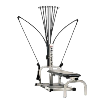
Owner's Manual
Assembly Instructions
For The Bowflex Motivator
Before you begin, you will need three wrenches, a cresent wrench, a 9/16", and a 1/2" open
end wrench, (It is useful to use the cresent wrench to hold one end of a bolt while tightening
with the other) and a phillips head (+) screw driver. Please follow these assembly instructions
carefully. If you experience any difficulty please call a Bowflex customer service representative
and ask for assistance. 1-800-269-3539.
Unpacking Your Motivator
Your Motivator comes in two boxes. One Square box and one long box. See Below
Contents of square box.
1 Base Frame
1 Pulley Frame
1 Lower Mast
1 Rear Legs
1 Standing Platform
1 Bench
1 Seat
2 Handgrips
1 Ankle Cuff
1 Parts and bolt bag
1 Training Manual
1 Set of Assembly Instructions
See Bolt Bag I.D. and size Guide
for Bolt Bag Contents
Please check to make sure all parts are
included. If you are missing any part, please
call a customer service representative at
1-800-269-3539.
Contents of long box.
1 Main Beam (Seat Rail)
1 Verticle, Rod Box, & Rod Pack Assembly
Advertisement
Table of Contents

Subscribe to Our Youtube Channel
Related Manuals for Bowflex Motivator


Summary of Contents for Bowflex Motivator
- Page 1 If you experience any difficulty please call a Bowflex customer service representative and ask for assistance. 1-800-269-3539. Unpacking Your Motivator Your Motivator comes in two boxes. One Square box and one long box. See Below Contents of square box. Contents of long box.
- Page 2 STEP 1. Have the appropriate bolts ready for the appropriate parts. Locate Base Frame and Pulley Frame. (Square box) Pulley Frame Attach pulley frame to base frame with four 3/8"x1" tap bolts and four 3/8" flat washers, tighten with a 9/16" wrench. See 1A. Base Frame Note: Leave pulleys and cables wrapped until assembly is complete.
- Page 3 STEP 3. Locate your Main Beam. (Long Box) This is the longest beam. (The head has a threaded hole on each side. You should also see a caution sticker located on the face of the beam which faces towards the ceiling.) Locate Rear Legs and attach to the bottom of the main beam with two tap bolts and 3/8"...
- Page 4 STEP 5 Locate the Vertical, Rod Box, and Rods. They have been preassembled and can be found in the long box. For identification see 5A Place unit onto upright of pulley frame. Align holes of vertical and upright. Secure vertical and pulley frame together with two 2 1/2" hex head bolts, two, 3/8"...
- Page 5 See 7A Place Standing Platform on base frame as seen in 7A. For instruction on how your Motivator Unwrap pulleys, cables and rods and folds for easy storage, see page 4 of your attach handgrips. See 7A...
- Page 6 Parts Identification and Size Guide Name: 3/8"x 6" Carriage Bolt Name: 3/8" Nylon Lock Nut Name: 3/8" x 4 1/2" Hex Head Bolt Part #: 82060 Part #: 90196 Part #: 82052 Quantity: 1 Quantity: 6 Quantity: 2 Name: 3/8" x 4 1/4" Hex Head Bolt Part #: 82054 Quantity: 1 Name: 1/4"x1"...
- Page 8 Lat Parts and bolts Name: 5/16" x 3/4" Tap Bolt Part #: 90206 Quantity: 2 Name: 3/8" Nylon Lock Nut (Nylock) Part #: 90196 Quantity: 2 Name: Shock Cord Part #: 95180 Quantity: 1...
Need help?
Do you have a question about the Motivator and is the answer not in the manual?
Questions and answers