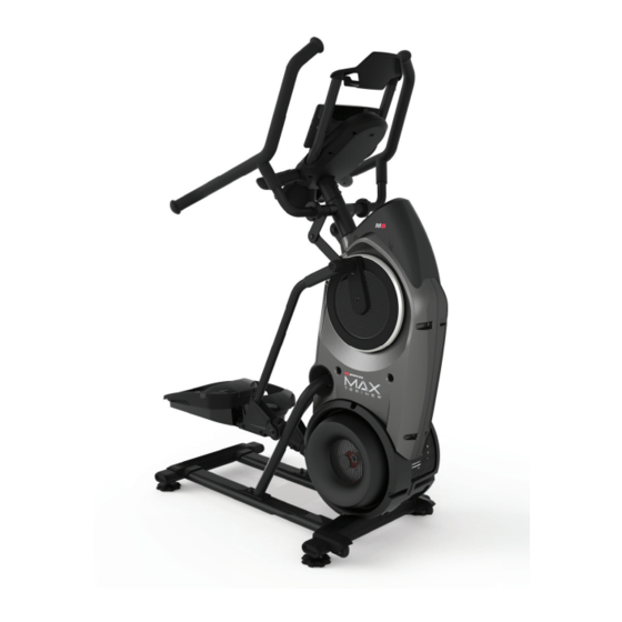
Bowflex MAX TRAINER M8 Owner's Manual
Hide thumbs
Also See for MAX TRAINER M8:
- User manual ,
- Troubleshooting manual (4 pages) ,
- Quick start manual (2 pages)
Advertisement
Quick Links
Advertisement

Summary of Contents for Bowflex MAX TRAINER M8
- Page 1 ™ ™ ™ O WN E R’S / A SSE MBLY MA N UAL O WN E R’S / A SSE MBLY MA N UAL...
- Page 2 | Nautilus (Shanghai) Fitness Equipments Co, Ltd, Room 1701 &1702, 1018 Changning Road, Changning District, Shanghai, China 200042, www.nautilus.cn - 86 21 6115 9668 | outside U.S. www.nautilusinternational.com | Printed in China | © 2018 Nautilus, Inc. | Bowflex, the Bowflex logo, Nautilus, the Nautilus logo, Schwinn, SelectTech, Max Trainer, and JRNY are trademarks owned or licensed by Nautilus, Inc.,...
- Page 3 IMPORTANT SAFETY INSTRUCTIONS When using an electrical appliance, basic precautions should always be followed, including the following: This icon means a potentially hazardous situation which, if not avoided, could result in death or serious injury. Obey the following warnings: Read and understand all warnings on this machine. Carefully read and understand the Assembly instructions.
- Page 4 Before using this equipment, obey the following warnings: Read and understand the complete Manual. Keep the Manual for future reference. Read and understand all warnings on this machine. If at any time the Warning labels become loose, unreadable or dislodged, replace the labels.
- Page 5 Safety Warning Labels and Serial Number WARNING! • Injury or death is possible if caution is not used while using this machine. • Keep children and pets away. • Read and follow all warnings on this machine. • Refer to the Owner’s Manual for additional warnings and safety information.
- Page 6 Specifications / Before Assembly Maximum User Weight: 136 kg ( 300 lbs.) Total Surface Area (footprint) of equipment: 9648.8 cm Maximum Pedal Height: 48.5 cm ( 19.1 inches ) 165.6 cm (65.2”) Machine Weight: 64 kg (141 lbs.) Power Requirements: Input Voltage: 100-240V AC, 50-60Hz, 0.5A Output Voltage: 9V DC, 1.5A 121.5 cm 78.2 cm (47.9”) DO NOT dispose of this product as refuse.
- Page 7 Parts ( 2 Boxes ) Box 1 Item Description Frame Shroud, Rear Foot Pad Insert, Front Foot Pad Insert Foot Pad Hardware Card Box 2 A decal has been applied to all right (“ R ”) and left (“ L ”) parts to assist with assembly. Item Description Item...
- Page 8 Hardware / Tools Item Description Item Description Socket Head Hex Screw, M8x1.25x20 Black Wave Washer, 17.2x22 Lock Washer, M8x14.8 Black Socket Head Hex Screw, M8x1.0x55 Black Washer, Flat M8x18 Black Lock Nut, M8 Black Socket Head Hex Screw, M10x1.5x25 Black Socket Head Hex Screw, M6x1.0x8 Black Washer, Flat M10x23 Black Socket Head Hex Screw, M6x1.0x20 CL10.9 Black...
- Page 9 Assembly 1. Attach Rail Assembly to Frame and then Release the Frame from the Shipping Plate Some components of the machine can be heavy or awkward. Use a second person when doing the assembly steps involving these parts. Do not do steps that involve heavy lifting or awkward movements on your own. NOTICE: Hand tighten hardware.
- Page 10 2. Attach Levelers to the Stabilizer Assembly Assembly / Owner’s Manual...
- Page 11 3. Carefully Lift the Frame Assembly from the Shipping Plate and Attach to the Stabilizer Assembly Some components of the machine can be heavy or awkward. Use a second person when doing the assembly steps involving these parts. Do not do steps that involve heavy lifting or awkward movements on your own. Lift the Frame Assembly from the exterior of the pivot assembly as indicated below.
- Page 12 4. Attach Stabilizer Shroud to the Frame Assembly Assembly / Owner’s Manual...
- Page 13 5. Attach Rear Shroud and Caps to the Frame Assembly NOTICE: Place the inside hook of the Rear Shroud on the Frame Assembly and then pivot it up into place. Assembly / Owner’s Manual...
- Page 14 6. Attach Legs to Frame Assembly Be aware that the Legs are connected and when either of these parts move the other does as well. 6 mm Assembly / Owner’s Manual...
- Page 15 7. Attach Pedals to Frame Assembly In order to avoid possible serious injury, when inserting the tube ends into the Leg Assemblies be careful to avoid fingers or hands being caught or pinched. 6 mm 13mm Assembly / Owner’s Manual...
- Page 16 8. Attach the Foot Platforms and then the Foot Pads to the Pedals Assembly / Owner’s Manual...
- Page 17 9. Cut the Shipping Zip-Tie that Secures the Cables, Connect the Cables, and Attach the Console Assem- bly and Media Capture Bar NOTICE: Do not let the Cables drop into the Frame Assembly. Do not cut or crimp the Console Cables. Once all hardware has been hand tightened, fully tighten the hardware with the 5mm hex wrench.


Need help?
Do you have a question about the MAX TRAINER M8 and is the answer not in the manual?
Questions and answers