Table of Contents
Advertisement
Advertisement
Table of Contents

Related Manuals for Asus VANGUARD B85


Summary of Contents for Asus VANGUARD B85
- Page 1 VANGUARD B85...
- Page 2 Product warranty or service will not be extended if: (1) the product is repaired, modified or altered, unless such repair, modification of alteration is authorized in writing by ASUS; or (2) the serial number of the product is defaced or missing.
-
Page 3: Table Of Contents
Contents Safety information ..................iv About this guide ..................iv Package contents ..................vi VANGUARD B85 specifications summary ..........vi Chapter 1 Product introduction Before you proceed ..............1-1 Motherboard overview ..............1-1 Central Processing Unit (CPU) ........... 1-3 System memory ................1-7 Expansion slots ................ -
Page 4: Safety Information
Safety information Electrical safety • To prevent electrical shock hazard, disconnect the power cable from the electrical outlet before relocating the system. • When adding or removing devices to or from the system, ensure that the power cables for the devices are unplugged before the signal cables are connected. If possible, disconnect all power cables from the existing system before you add a device. -
Page 5: Conventions Used In This Guide
Refer to the following sources for additional information and for product and software updates. ASUS websites The ASUS website provides updated information on ASUS hardware and software products. Refer to the ASUS contact information. Optional documentation Your product package may include optional documentation, such as warranty flyers, that may have been added by your dealer. -
Page 6: Package Contents
® * Due to chipset limitation, memory modules higher than 1600MHz will run at 1600MHz frequency for better stability. ** Refer to www.asus.com or this user manual for the Memory QVL (Qualified Vendors List). Expansion 1 x PCI Express 3.0/2.0 x16 slot Slots 1 x PCI Express 2.0 x16 slot [black] (max. - Page 7 - Supports Jack-Detection, Multi-streaming and Front Panel Jack- Retasking Intel B85 Express Chipset - supports ASUS USB 3.0 Boost ® - 2 x USB3.0/2.0 ports at mid-board for front panel support - 4 x USB3.0/2.0 ports at back panel (blue) - 8 x USB2.0/1.1 ports (6 ports at mid-board, 2 ports at back panel)
- Page 8 Other Special - USB 3.0 Boost featuring speedy USB3.0 transmission Features - Ai Charger - ASUS UEFI BIOS EZ Mode featuring friendly graphics user interface - AI Suite 3 - ASUS Q-Connector - ASUS Q-Shield - ASUS Q-LED (CPU, DRAM, VGA, Boot Device LED)
- Page 9 BIOS 128 Mb Flash ROM, UEFI AMI BIOS, PnP, DMI 2.7, WfM2.0, SM BIOS 2.7, ACPI 5.0, Multi-language BIOS, ASUS EZ Flash 2, ASUS CrashFree BIOS 3, My Favorites, Quick Note, Last Modified log, F12 PrintScreen, F3 Shortcut functions, and ASUS DRAM SPD (Serial...
-
Page 11: Chapter 1 Product Introduction
1.2.2 Screw holes Place eight screws into the holes indicated by circles to secure the motherboard to the chassis. Do not overtighten the screws! Doing so can damage the motherboard. ASUS VANGUARD B85... -
Page 12: Motherboard Layout
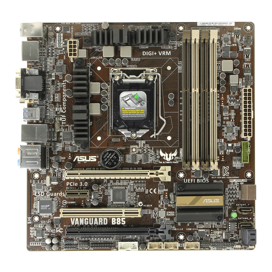
Place this side towards the rear of the chassis 1.2.3 Motherboard layout 24.4cm(9.6in) KBMS_USB34 CPU_FAN CHA_FAN3 DIGI+ DP_HDMI EATX12V CHA_FAN2 USB3_E34 LAN_USB3_5E2 AUDIO BATTERY VGA_LED PCIEX16_1 BOOT_DEVICE_LED Intel I217 V PCIEX1_1 Super Intel ® 1083 PCI1 SATA6G_3 SB_PWR SATA6G_4 16Mb BIOS PCIEX16_2 SPIDF_OUT... -
Page 13: Central Processing Unit (Cpu)
Central Processing Unit (CPU) This motherboard comes with a surface mount LGA1150 socket designed for the Intel ® generation Core™ i7 / Core™ i5 / Core™ i3, Pentium , Celeron processors. ® ® VANGUARD B85 CPU socket LGA1150 ASUS VANGUARD B85... -
Page 14: Installing The Cpu
Contact your retailer immediately if the PnP cap is missing, or if you see any damage to the PnP cap/socket contacts/motherboard components. ASUS will shoulder the cost of repair only if the damage is shipment/ transit-related. -
Page 15: Cpu Heatsink And Fan Assembly Installation
1.3.2 CPU heatsink and fan assembly installation Apply the Thermal Interface Material to the CPU heatsink and CPU before you install the heatsink and fan if necessary. ASUS VANGUARD B85... - Page 16 To install the CPU heatsink and fan assembly To uninstall the CPU heatsink and fan assembly Chapter 1: Product introduction...
-
Page 17: System Memory
CPU’s capabilities and other installed devices. • The maximum 32GB memory capacity can be supported with 8GB or above DIMMs. ASUS will update the memory QVL once the DIMMs are available in the market. ASUS VANGUARD B85... - Page 18 For system stability, use a more efficient memory cooling system to support a full memory load (4 DIMMs) or overclocking condition. • Visit the ASUS website at: www.asus.com for the latest QVL. VANGUARD B85 Motherboard Qualified Vendors Lists (QVL) DDR3 2666 MHz capability...
- Page 19 11-11-11-30 - • • CMX8GX3M2A1600C9 CORSAIR 8GB(2x 4GB ) 9-9-9-24 1.65 • • (Ver3.19)(XMP) CMZ16GX3M2A1600C10 CORSAIR 16GB(2x 8GB ) 10-10-10-27 1.5 • • (Ver.3.24)(XMP) CORSAIR CMZ16GX3M4A1600C9(XMP) 16GB(4x 4GB ) 9-9-9-24 • • continued on the next page ASUS VANGUARD B85...
- Page 20 DDR3 1600 MHz capability DIMM socket Chip support (Optional) Vendors Part No. Size Chip No. Timing Voltage Brand 2 DIMMs 4 DIMMs CMZ32GX3M4X1600C10 CORSAIR 32GB ( 4x 8GB ) DS 10-10-10-27 1.5 • • (Ver2.2)(XMP) CMZ4GX3M1A1600C9 ( CORSAIR 4GB ( 1x 4GB ) 9-9-9-24 •...
- Page 21 • KINGMAX FLFE85F-C8KL9 KINGMAX KFC8FNLXF-DXX-15A • • KINGMAX FLFF65F-C8KL9 KINGMAX KFC8FNLBF-GXX-12A - • KINGMAX FLFF65F-C8KL9 KINGMAX KFC8FNLXF-DXX-15A • • KINGSTON KVR1333D3E9S/4G Elpida J2108ECSE-DJ-F • • KINGSTON KVR1333D3N9H/4G ELPIDA J2108BDBG-GN-F • • continued on the next page ASUS VANGUARD B85 1-11...
- Page 22 Dual-channel memory configuration. • 4 DIMMs: Supports four (4) modules inserted into both the beige and brown slots as two pairs of Dual-channel memory configuration. Visit the ASUS website at www.asus.com for the latest QVL. 1-12 Chapter 1: Product introduction...
-
Page 23: Installing A Dimm
Simultaneously press the retaining clips outward to unlock the DIMM. Support the DIMM lightly with your fingers when pressing the retaining clips. The DIMM might get damaged when it flips out with extra force. Remove the DIMM from the socket. DIMM notch ASUS VANGUARD B85 1-13... -
Page 24: Expansion Slots
Expansion slots Unplug the power cord before adding or removing expansion cards. Failure to do so may cause you physical injury and damage motherboard components. PCIEX16_1 PCIEX1_1 PCI1 PCIEX16_2 Slot No. Slot Description PCIe 3.0/2.0 x16_1 slot PCIe 2.0 x1_1 slot PCI x1 slot PCIe 2.0 x16_1 slot 1-14... - Page 25 – – – – – – – PCIe x1_1 shared – – – – – – – PCI1 – shared – – – – – – Intel LAN – – – – shared – – – ASUS VANGUARD B85 1-15...
-
Page 26: Jumpers
Normal Clear RTC (Default) VANGUARD B85 Clear RTC RAM To erase the RTC RAM: Turn OFF the computer and unplug the power cord. Move the jumper cap from pins 1-2 (default) to pins 2-3. Keep the cap on pins 2-3 for about 5-10 seconds, then move the cap back to pins 1-2. -
Page 27: Connectors
7.1 channel configurations, the function of this port becomes Front Speaker Out. Microphone port (pink). This port connects to a microphone. Side Speaker Out port (gray). This port connects the side speaker in an 8-channel audio configuration. ASUS VANGUARD B85 1-17... - Page 28 Refer to the audio configuration table for the function of the audio ports in 2.1, 4.1, 5.1, or 7.1 channel configuration. Audio 2, 4, 6, or 8-channel configuration Port Headset 4.1 channel 5.1 channel 7.1 channel 2.1 channel Light Blue Line In Line in Line in...
-
Page 29: Internal Connectors
• If you are uncertain about the minimum power supply requirement for your system, refer to the Recommended Power Supply Wattage Calculator at http://support.asus. com/PowerSupplyCalculator/PSCalculator.aspx?SLanguage=en-us for details. Digital audio connector (4-1 pin SPDIF_OUT) This connector is for an additional Sony/Philips Digital Interface (S/PDIF) port. Connect the S/PDIF Out module cable to this connector, then install the module to a slot opening at the back of the system chassis. - Page 30 PIN 1 HD-audio-compliant Legacy AC’97 pin definition compliant definition VANGUARD B85 Front panel audio connector • We recommend that you connect a high-definition front panel audio module to this connector to avail of the motherboard’s high-definition audio capability. • If you want to connect a high-definition front panel audio module to this connector, set the Front Panel Type item in the BIOS setup to [HD].
- Page 31 CHA FAN IN CHA_FAN4 CHA_FAN1 VANGUARD B85 VANGUARD B85 Fan connectors • DO NOT forget to connect the fan cables to the fan connectors. Insufficient air flow inside the system may damage the motherboard components. These are not jumpers! Do not place jumper caps on the fan connectors! •...
-
Page 32: Chassis Intrusion Connector
Remove the jumper caps only when you intend to use the chassis intrusion detection feature. CHASSIS VANGUARD B85 PIN 1 VANGUARD B85 Chassis intrusion connector Intel B85 Serial ATA 6.0Gb/s connector (7-pin SATA6G_1~4 [brown]) ® This connector connects to Serial ATA 6.0 Gb/s hard disk drives via Serial ATA 6.0 Gb/s signal cables. - Page 33 RSATA_RXP5 SATA3G_6 RSATA_TXP6 RSATA_TXN6 RSATA_RXN6 VANGUARD B85 RSATA_RXP6 VANGUARD B85 SATA 3.0Gb/s connectors When using hot-plug and NCQ, set the SATA Mode Selection item in the BIOS to [AHCI]. See section 2.6.3 SATA Configuration for details. ASUS VANGUARD B85 1-23...
- Page 34 USB-chargeable devices, optimized power efficiency, and backward compatibility with USB 2.0. USB3_12 PIN 1 USB3+5V USB3+5V IntA_P1_SSRX- IntA_P2_SSRX- IntA_P1_SSRX+ IntA_P2_SSRX+ IntA_P1_SSTX- IntA_P2_SSTX- IntA_P1_SSTX+ IntA_P2_SSTX+ IntA_P1_D- IntA_P2_D- IntA_P1_D+ IntA_P2_D+ VANGUARD B85 VANGUARD B85 USB3.0 Front panel connector The USB 3.0 module is purchased separately. 1-24 Chapter 1: Product introduction...
-
Page 35: System Panel Connector
PWRSW RESET VANGUARD B85 * Requires an ATX power supply VANGUARD B85 System panel connector • System power LED (2-pin PWR_LED) This 2-pin connector is for the system power LED. Connect the chassis power LED cable to this connector. The system power LED lights up when you turn on the system power, and blinks when the system is in sleep mode. -
Page 36: Onboard Led
USB1314 PIN 1 PIN 1 PIN 1 VANGUARD B85 VANGUARD B85 USB2.0 connectors Never connect a 1394 cable to the USB connectors. Doing so will damage the motherboard! The USB 2.0 module is purchased separately. Onboard LED Standby Power LED The motherboard comes with a standby power LED that lights up to indicate that the system is ON, in sleep mode, or in soft-off mode. -
Page 37: Software Support
Place the Support DVD into the optical drive. If Autorun is enabled in your computer, the DVD automatically displays the Specials screen which lists the unique features of your ASUS motherboard. Click Drivers, Utilities, AHCI Driver, Manual, Contact and Specials tabs to display their respective menus. - Page 38 • Local Administrator rights on the target machine The Intel SBA does not support the 800 x 600 screen resolution. ® Visit the ASUS website at www.asus.com for the latest CPU QVL (Qualified Vendors List). 1-28 Chapter 1: Product introduction...
-
Page 39: Chapter 2 Bios Information
Managing and updating your BIOS Save a copy of the original motherboard BIOS file to a USB flash disk in case you need to restore the BIOS in the future. Copy the original motherboard BIOS using the ASUS Update utility. -
Page 40: Asus Ez Flash
2.1.2 ASUS EZ Flash 2 The ASUS EZ Flash 2 feature allows you to update the BIOS without using an OS-based utility. Before you start using this utility, download the latest BIOS file from the ASUS website at www.asus.com. To update the BIOS using EZ Flash 2: Insert the USB flash disk that contains the latest BIOS file to the USB port. -
Page 41: Asus Crashfree Bios 3 Utility
2.1.3 ASUS CrashFree BIOS 3 utility The ASUS CrashFree BIOS 3 is an auto recovery tool that allows you to restore the BIOS file when it fails or gets corrupted during the updating process. You can restore a corrupted BIOS file using the motherboard support DVD or a USB flash drive that contains the updated BIOS file. - Page 42 Insert the USB flash drive with the latest BIOS file and BIOS Updater to the USB port. Boot your computer. When the ASUS Logo appears, press <F8> to show the BIOS Boot Device Select Menu. Insert the support DVD into the optical drive and select the optical drive as the boot device.
- Page 43 Select the Load Optimized Defaults item under the Exit menu. Refer to section 2.10 Exit menu for details. • Ensure to connect all SATA hard disk drives after updating the BIOS file if you have disconnected them. ASUS VANGUARD B85...
-
Page 44: Bios Setup Program
The BIOS setup screens shown in this section are for reference purposes only, and may not exactly match what you see on your screen. • Visit the ASUS website at www.asus.com to download the latest BIOS file for this motherboard. •... -
Page 45: Advanced Mode
The Advanced Mode provides advanced options for experienced end-users to configure the BIOS settings. The figure below shows an example of the Advanced Mode. Refer to the following sections for the detailed configurations. To access the EZ Mode, click Exit, then select ASUS EZ Mode or press <F7>. ASUS VANGUARD B85... -
Page 46: Menu Bar
Back button Menu items Menu bar Configuration fields General help Last modified settings Pop-up window Submenu item Navigation keys Quick note Scroll bar Menu bar The menu bar on top of the screen has the following main items: My Favorites For saving the frequently-used system settings and configuration Main For changing the basic system configuration... -
Page 47: Submenu Items
The Quick Note function does not support the following keyboard functions: delete, cut, copy and paste. • You can only use the English letters to type your notes. Last Modified button This button shows the items that you last modified and saved in BIOS Setup. ASUS VANGUARD B85... -
Page 48: My Favorites
My Favorites MyFavorites is your personal space where you can easily save and access your favorite BIOS items. Adding items to My Favorites To add frequently-used BIOS items to My Favorites: Use the arrow keys to select an item that you want to add. When using a mouse, hover the pointer to the item. -
Page 49: Main Menu
RAM to clear the BIOS password. See section 1.6 Jumpers for information on how to erase the RTC RAM. • The Administrator or User Password items on top of the screen show the default Not Installed. After you set a password, these items show Installed. ASUS VANGUARD B85 2-11... -
Page 50: Administrator Password
Administrator Password If you have set an administrator password, we recommend that you enter the administrator password for accessing the system. Otherwise, you might be able to see or change only selected fields in the BIOS setup program. To set an administrator password: Select the Administrator Password item and press <Enter>. -
Page 51: Ai Tweaker Menu
Target DMI/PEG Clock : xxxxMHz Displays the target DMI/PEG clock. Target iGPU Speed : xxxxMHz Displays the target iGPU speed. 2.5.1 ASUS MultiCore Enhancement [Auto] [Auto] Set to [Auto] for optimized performance under XMP/Manual/User-defined memory frequency mode. [Disabled] Allows you to set to default core ratio settings. - Page 52 2.5.2 CPU Core Ratio [Auto] Allows you to set the CPU core ratio automatically or manually. [Auto] Sets all CPU Core Ratio to Intel CPU default settings automatically. ® [Sync All Cores] Allows you to set CPU Core Ratio settings for all cores. [Per Core] Allows you to set CPU Core Ratio individually.
-
Page 53: Dram Timing Control
Configuration options: [Auto] [1 DRAM Clock] – [16 DRAM Clock] DRAM READ to PRE Time [Auto] Configuration options: [Auto] [1 DRAM Clock] – [15 DRAM Clock] DRAM FOUR ACT WIN Time [Auto] Configuration options: [Auto] [1 DRAM Clock] – [255 DRAM Clock] ASUS VANGUARD B85 2-15... - Page 54 DRAM WRITE to READ Delay [Auto] Configuration options: [Auto] [1 DRAM Clock] – [15 DRAM Clock] DRAM CKE Minimum pulse width [Auto] Configuration options: [Auto] [1 DRAM Clock] – [15 DRAM Clock] DRAM CAS# Write to Latency [Auto] Configuration options: [Auto] [1 DRAM Clock] – [31 DRAM Clock] RTL IOL control DRAM RTL (CHA_R0D0) [Auto] Configuration options: [Auto] [1] - [63]...
- Page 55 Channel A DIMM Control [Enable Bot...] Configuration options: [Enable Both DIMMS] [Disable DIMM0] [Disable DIMM1] [Disable Both DIMMS] Channel B DIMM Control [Enable Bot...] Configuration options: [Enable Both DIMMS] [Disable DIMM0] [Disable DIMM1] [Disable Both DIMMS] ASUS VANGUARD B85 2-17...
- Page 56 Scrambler Setting [Optimized ...] Configuration options: [Optimized (ASUS)] [Default (MRC)] MCH Full Check [Auto] Allows you to enable, disable or automatically set the MCH Full Check function. Configuration options: [Auto] [Enabled] [Disabled] Skew Control Adjust these items may enhance the DRAM overclocking capability and stability.
-
Page 57: Cpu Power Management
The following first three items appear only when you set the Turbo Mode to [Enabled]. Turbo Mode Parameters Long Duration Package Power Limit [Auto] Allows you to limit the turbo ratio’s long duration package power. Use the <+> and <-> keys to adjust the value. ASUS VANGUARD B85 2-19... - Page 58 Package Power Time Window [Auto] Allows you to set the package power time window. Use the <+> and <-> keys to adjust the value. Short Duration Package Power Limit [Auto] Allows you to limit the turbo ratio’s long duration power. Use the <+>...
- Page 59 [Adaptive Mode] and allows you to set the CPU core voltage offset. The values range from 0.001V to 0.999V with a 0.001V interval. The following two items appear only when you set the CPU Core Voltage to [Adaptive Mode]. ASUS VANGUARD B85 2-21...
- Page 60 Additional Turbo Mode CPU Core Voltage [Auto] This item allows you to set the additional turbo mode CPU core voltage. The values range from 0.001V to 1.920V with a 0.001V interval. Total Adaptive Mode CPU Core Voltage [Auto] This item allows you to set the total adaptive mode CPU core voltage. The values range from 0.001V to 1.920V with a 0.001V interval.
- Page 61 DRAM frequency. The values range from 0.001V to 0.999V with a 0.001V interval. 2.5.18 CPU Analog I/O Voltage Offset Mode Sign [+] This item allows you to set the CPU analog I/O voltage offset mode sign. Configuration options: [+] [-]. ASUS VANGUARD B85 2-23...
- Page 62 CPU Analog I/O Voltage Offset [Auto] This item allows you to set the CPU analog I/O voltage offset. Increase the value when increasing DRAM frequency. The values range from 0.001V to 0.999V with a 0.001V interval. 2.5.19 CPU Digital I/O Voltage Offset Mode Sign [+] This item allows you to set the CPU digital I/O voltage offset mode sign.
-
Page 63: Advanced Menu
The items shown in submenu may be different due to the CPU you installed. Intel Adaptive Thermal Monitor [Enabled] ® [Enabled] Enables the overheated CPU to throttle its clock speed to cool down. [Disabled] Disables the CPU thermal monitor function. ASUS VANGUARD B85 2-25... - Page 64 Hyper-threading [Enabled] The Intel Hyper-Threading Technology allows a hyper-threading processor to appear as two logical processors to the operating system, allowing the operating system to schedule two threads or processes simultaneously. [Enabled] Two threads per activated core are enabled. [Disabled] Only one thread per activated core is enabled.
-
Page 65: Pch Configuration
Allows you to control the Active State Power Managemennt on both NB and SB side of the DMI Link. Configuration options: [Auto] [Enabled] [Disabled] ASPM Support [Disabled] Allows you to set the ASPM support. Configuration options: [Disabled] [Auto] [L0s] [L1] L0sL1]. ASUS VANGUARD B85 2-27... -
Page 66: Intel Rapid Start Technology
PCIe Speed [Auto] Allows you to select the PCI Express port speed. Configuration options: [Auto] [Gen1] [Gen2] Intel Rapid Start Technology ® Intel Rapid Start Technology [Disabled] ® Allows you to enable or disable Intel Rapid Start Technology. Configuration options: ®... -
Page 67: System Agent Configuration
Allows you to select the amount of system memory allocated to DVMT 5.0 used by the iGPU. Configuration options: [Auto] [32M] [64M] [96M] [128M] [160M] [192M] [224M] [256M] [288M][320M] [352M] [384M] [416M] [448M] [480M] [512M] [1024M] ASUS VANGUARD B85 2-29... -
Page 68: Dmi Configuration
Render Standby [Auto] Allows you to enable or disable Intel Graphics Render Standby support to reduce ® iGPU power use when the system is idle. Configuration options: [Auto] [Disabled] [Enabled] iGPU Multi-Monitor [Disabled] Allows you to enable the iGPU Multi-Monitor. For LucidLogix Virtu MVP function support, set this item to [Enabled] to empower both integrated and discrete graphics. -
Page 69: Usb Configuration
USB Single Port Control USB3_1/2/5/E2/E3/E4 [Enabled] Allows you to enable or disable an individual USB port. Refer to the section 1.2.3 Motherboard layout in this user manual for the locations of the USB ports. Configuration options: [Enabled] [Disabled]. ASUS VANGUARD B85 2-31... -
Page 70: Platform Misc Configuration
USB3, 4, 9~14 [Enabled] Allows you to enable or disable an individual USB port. Refer to the section 1.2.3 Motherboard layout in this user manual for the locations of the USB ports. Configuration options: [Enabled] [Disabled]. 2.6.7 Platform Misc Configuration The items in this menu allow you to configure the Platform Misc. - Page 71 Enables Ring to generate a wake event. Power On By RTC [Disabled] [Disabled] Disables RTC to generate a wake event. [Enabled] When set to [Enabled], the items RTC Alarm Date (Days) and Hour/ Minute/Second will become user-configurable with set values. ASUS VANGUARD B85 2-33...
-
Page 72: Monitor Menu
2.6.10 Network Stack Network Stack [Disabled] This item allows user to disable or enable the UEFI network stack. Configuration options: [Disabled] [Enabled] The following two items appear only when you set the previous item to [Enabled]. Ipv4 PXE Support [Enabled] This item allows user to disable or enable the Ipv4 PXE Boot support. - Page 73 Use the <+> and <-> keys to adjust the maximum CPU fan duty cycle. The values range from 20% to 100%. When the CPU temperature reaches the upper limit, the CPU fan will operate at the maximum duty cycle. CPU Lower Temperature [20] Displays the lower limit of the CPU temperature. ASUS VANGUARD B85 2-35...
- Page 74 CPU Fan Min. Duty Cycle(%) [20] Use the <+> and <-> keys to adjust the minimum CPU fan duty cycle. The values range from 20% to 100%. When the CPU temperature is under the lower limit, the CPU fan will operate at the minimum duty cycle. 2.7.5 Chassis Fan 1/2/3/4 Q-Fan Control [Enabled] [Disabled]...
-
Page 75: Boot Menu
Only hard drives connected to SATA ports will be detected during POST. Any hardware change will disable fast boot. [Boot Drive Only] Only boot drive connected to SATA ports will be detected during POST. Any hardware change will disable fast boot. ASUS VANGUARD B85 2-37... - Page 76 USB Support [Partial Initialization] [Disabled] All USB devices will not be available until OS boot up for a fastest POST time. [Full Initialization] All USB devices will be available during POST. This process will extend the POST time. [Partial Initialization] For a faster POST time, only the USB ports with keyboard and mouse connections will be detected.
- Page 77 Windows UEFI mode. ® [Disabled] Disable the CSM to fully support the Windows Security Update and ® Security Boot. The following four items appear when you set Launch CSM to [Enabled]. ASUS VANGUARD B85 2-39...
-
Page 78: Secure Boot
Boot Devices Control [UEFI and L...] Allows you to select the type of devices that you want to boot up. Configuration options: [UEFI and Legacy OPROM] [Legacy OPROM only] [UEFI only] Boot from Network Devices [Legacy OPR...] Allows you to select the type of network devices that you want to launch. Configuration options: [Legacy OPROM first] [UEFI driver first] [Ignore] Boot from Storage Devices [Legacy OPR...] Allows you to select the type of storage devices that you want to launch. - Page 79 Append db from file Allows you to load the additional db from a storage device so that more images can be loaded securely. The DB file must be formatted as a UEFI variable structure with time-based authenticated variable. ASUS VANGUARD B85 2-41...
-
Page 80: Boot Option Priorities
• To select the boot device during system startup, press <F8> when ASUS Logo appears. • To access Windows OS in Safe Mode, do any of the following: •... -
Page 81: Tools Menu
<Enter> to display the submenu. 2.9.1 ASUS EZ Flash 2 Utility Allows you to run ASUS EZ Flash 2. Press [Enter] to launch the ASUS EZ Flash 2 screen. For more details, see section 2.1.2 ASUS EZ Flash 2. 2.9.2 ASUS Overclocking Profile This item allows you to store or load multiple BIOS settings. -
Page 82: Exit Menu
This option allows you to exit the Setup program without saving your changes. When you select this option or if you press <Esc>, a confirmation window appears. Select Yes to discard changes and exit. ASUS EZ Mode This option allows you to enter the EZ Mode screen. Launch EFI Shell from filesystem device This option allows you to attempt to launch the EFI Shell application (shellx64.efi) from one of... -
Page 83: Appendices
Cet appareil est conforme aux normes CNR exemptes de licence d’Industrie Canada. Le fonctionnement est soumis aux deux conditions suivantes : (1) cet appareil ne doit pas provoquer d’interférences et (2) cet appareil doit accepter toute interférence, y compris celles susceptibles de provoquer un fonctionnement non souhaité de l’appareil. VANGUARD B85... -
Page 84: Canadian Department Of Communications Statement
ASUS Recycling/Takeback Services ASUS recycling and takeback programs come from our commitment to the highest standards for protecting our environment. We believe in providing solutions for you to be able to responsibly recycle our products, batteries, other components as well as the packaging materials. -
Page 85: Asus Contact Information
+1-812-282-3777 +1-510-608-4555 Web site usa.asus.com Technical Support Telephone +1-812-282-2787 Support fax +1-812-284-0883 Online support support.asus.com ASUS COMPUTER GmbH (Germany and Austria) Address Harkort Str. 21-23, D-40880 Ratingen, Germany +49-2102-959911 Web site www.asus.de Online contact www.asus.de/sales Technical Support Telephone +49-1805-010923* Support Fax... - Page 86 Appendices...
Need help?
Do you have a question about the VANGUARD B85 and is the answer not in the manual?
Questions and answers