Asus B85M-E Manual
Hide thumbs
Also See for B85M-E:
- User manual (76 pages) ,
- Quick start manual (12 pages) ,
- E-manual (75 pages)
Table of Contents
Advertisement
Advertisement
Table of Contents

Related Manuals for Asus B85M-E


Summary of Contents for Asus B85M-E
- Page 1 B85M-E B85M-E/CSM...
- Page 2 Product warranty or service will not be extended if: (1) the product is repaired, modified or altered, unless such repair, modification of alteration is authorized in writing by ASUS; or (2) the serial number of the product is defaced or missing.
-
Page 3: Table Of Contents
Contents Safety information ..................iv About this guide ..................iv Package contents ..................vi B85M-E specifications summary ............... vi Product introduction Before you proceed ..............1-1 Motherboard overview ..............1-1 Central Processing Unit (CPU) ........... 1-3 System memory ................1-7 Expansion slots ................ -
Page 4: Safety Information
Safety information Electrical safety • To prevent electrical shock hazard, disconnect the power cable from the electrical outlet before relocating the system. • When adding or removing devices to or from the system, ensure that the power cables for the devices are unplugged before the signal cables are connected. If possible, disconnect all power cables from the existing system before you add a device. -
Page 5: Conventions Used In This Guide
Refer to the following sources for additional information and for product and software updates. ASUS websites The ASUS website provides updated information on ASUS hardware and software products. Refer to the ASUS contact information. Optional documentation Your product package may include optional documentation, such as warranty flyers, that may have been added by your dealer. -
Page 6: Package Contents
4 x DIMM, max. 32GB, DDR3 1600 / 1333 / 1066 MHz, non-ECC, un- buffered memory Dual-channel memory architecture * Refer to www.asus.com for the latest Memory QVL (Qualified Vendors List). ® ** Due to Intel chipset limitation, the DDR3 1600MHz and higher memory modules on XMP mode will run at the maximum transfer rate of DDR3 1600MHz. - Page 7 ASUS Exclusive Features: ASUS unique features - ASUS USB 3.0 Boost - ASUS Network iControl - ASUS GPU Boost - ASUS UEFI BIOS (EZ Mode) ASUS Quiet Thermal Solution: - ASUS Fan Xpert 2 ASUS EZ DIY: - ASUS CrashFree BIOS 3 - ASUS EZ Flash 2 - ASUS MyLogo 2™...
- Page 8 1 x 4-pin ATX 12V power connector BIOS features 128 Mb Flash ROM, EFI BIOS, PnP, DMI v2.0, WfM2.0, SM BIOS v2.7, ACPI v2.0a, SLP 3.0, EUP-ready, Multi-language BIOS, ASUS EZ Flash 2, ASUS CrashFree BIOS 3 Manageability WOL by PME, WOR by PME, PXE...
-
Page 9: Product Introduction
1.2.2 Screw holes Place six screws into the holes indicated by circles to secure the motherboard to the chassis. Do not overtighten the screws! Doing so can damage the motherboard. ASUS B85M-E... -
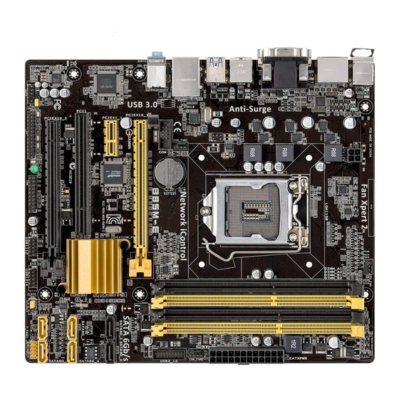
Page 10: Motherboard Layout
Place this side towards the rear of the chassis B85M-E 1.2.3 Motherboard layout 21.3cm(8.4in) KBMS CPU_FAN ATX12V 1255 HDMI_DP USB_34 USB3_56 CHA_FAN1 8111F LAN_USB910 BATTERY AUDIO B85M-E PCIEX16_1 SATA3G_1 SATA3G_2 PCIEX1_1 1083 Super Intel ® 16MB BIOS PCI1 SATA6G_3 SATA6G_4... -
Page 11: Central Processing Unit (Cpu)
Central Processing Unit (CPU) This motherboard comes with a surface mount LGA1150 socket designed for the Intel ® generation Core™ i7 / Core™ i5 / Core™ i3, Pentium , Celeron processors. ® ® B85M-E B85M-E CPU socket LGA1150 ASUS B85M-E... -
Page 12: Installing The Cpu
Contact your retailer immediately if the PnP cap is missing, or if you see any damage to the PnP cap/socket contacts/motherboard components. ASUS will shoulder the cost of repair only if the damage is shipment/ transit-related. -
Page 13: Cpu Heatsink And Fan Assembly Installation
1.3.2 CPU heatsink and fan assembly installation Apply the Thermal Interface Material to the CPU heatsink and CPU before you install the heatsink and fan if necessary. ASUS B85M-E... - Page 14 To install the CPU heatsink and fan assembly To uninstall the CPU heatsink and fan assembly Chapter 1: Product introduction...
-
Page 15: System Memory
CPU’s capabilities and other installed devices. • The maximum 32GB memory capacity can be supported with 8GB or above DIMMs. ASUS will update the memory QVL once the DIMMs are available in the market. ASUS B85M-E... -
Page 16: Installing A Dimm
For system stability, use a more efficient memory cooling system to support a full memory load (4 DIMMs) or overclocking condition. • Visit the ASUS website at: www.asus.com for the latest QVL. 1.4.3 Installing a DIMM Unplug the power supply before adding or removing DIMMs or other system components. -
Page 17: Expansion Slots
When using PCI cards on shared slots, ensure that the drivers support “Share IRQ” or that the cards do not need IRQ assignments. Otherwise, conflicts will arise between the two PCI groups, making the system unstable and the card inoperable. ASUS B85M-E... -
Page 18: Pci Slot
B85M-E Normal Clear RTC (Default) B85M-E Clear RTC RAM To erase the RTC RAM: Turn OFF the computer and unplug the power cord. Move the jumper cap from pins 1-2 (default) to pins 2-3. Keep the cap on pins 2-3 for about 5-10 seconds, then move the cap back to pins 1-2. -
Page 19: Connectors
Line In port (light blue). This port connects to the tape, CD, DVD player, or other audio sources. Line Out port (lime). This port connects to a headphone or a speaker. In the 4, 6 and 8-channel configurations, the function of this port becomes Front Speaker Out. ASUS B85M-E 1-11... - Page 20 Microphone port (pink). This port connects to a microphone. Refer to the audio configuration table for the function of the audio ports in 2, 4, 6, or 8- channel configuration. Audio 2, 4, 6, or 8-channel configuration Headset Port 4-channel 6-channel 8-channel 2-channel...
-
Page 21: Internal Connectors
The system may become unstable or may not boot up if the power is inadequate. • If you are uncertain about the minimum power supply requirement for your system, refer to the Recommended Power Supply Wattage Calculator at http://support.asus. com/PowerSupplyCalculator/PSCalculator.aspx?SLanguage=en-us for details. ASUS B85M-E 1-13... - Page 22 B85M-E HD-audio-compliant Legacy AC’97 pin definition compliant definition B85M-E Front panel audio connector • We recommend that you connect a high-definition front panel audio module to this connector to avail of the motherboard’s high-definition audio capability. • If you want to connect a high-definition front panel audio module to this connector, set the Front Panel Type item in the BIOS setup to [HD].
- Page 23 The CPU_FAN connector supports a CPU fan of maximum 2A (24 W) fan power. Only the 4-pin CPU fan supports the ASUS Fan Xpert 2 feature. Speaker connector (4-pin SPEAKER) The 4-pin connector is for the chassis-mounted system warning speaker. The speaker allows you hear system beeps and warnings.
- Page 24 This connector is for a serial (COM) port. Connect the serial port module cable to this connector, then install the module to a slot opening at the back of the system chassis. PIN 1 B85M-E B85M-E Serial port (COM) connector The COM module is purchased separately. Intel B85 Serial ATA 6.0Gb/s connector (7-pin SATA6G_1~4 [yellow]) ®...
- Page 25 PIN 1 B85M-E +HD_LED RESET B85M-E System panel connector • System power LED (2-pin PWR_LED) This 2-pin connector is for the system power LED. Connect the chassis power LED cable to this connector. The system power LED lights up when you turn on the system power, and blinks when the system is in sleep mode.
- Page 26 IntA_P1_SSRX- Vbus Vbus PIN 1 B85M-E USB3.0 Front panel connector The USB 3.0 module is purchased separately. USB 2.0 connectors (10-1 pin USB1112, USB1314) These connectors are for USB 2.0 ports. Connect the USB module cable to any of these connectors, then install the module to a slot opening at the back of the system chassis.
-
Page 27: Onboard Leds
Remove the jumper caps only when you intend to use the chassis intrusion detection feature. CHASSIS B85M-E B85M-E Chassis intrusion connector Onboard LEDs Standby Power LED The motherboard comes with a standby power LED that lights up to indicate that the system is ON, in sleep mode, or in soft-off mode. -
Page 28: Software Support
Place the Support DVD into the optical drive. If Autorun is enabled in your computer, the DVD automatically displays the Specials screen which lists the unique features of your ASUS motherboard. Click Drivers, Utilities, AHCI Driver, Manual, Contact and Specials tabs to display their respective menus. - Page 29 Management Engine Interface must be installed and running.) ® • Local Administrator rights on the target machine The Intel SBA does not support the 800 x 600 screen resolution. ® Visit the ASUS website at www.asus.com for the latest CPU QVL (Qualified Vendors List). ASUS B85M-E 1-21...
-
Page 30: Bios Information
Managing and updating your BIOS Save a copy of the original motherboard BIOS file to a USB flash disk in case you need to restore the BIOS in the future. Copy the original motherboard BIOS using the ASUS Update utility. -
Page 31: Asus Ez Flash
2.1.2 ASUS EZ Flash 2 The ASUS EZ Flash 2 feature allows you to update the BIOS without using an OS-based utility. Before you start using this utility, download the latest BIOS file from the ASUS website at www.asus.com. To update the BIOS using EZ Flash 2: Insert the USB flash disk that contains the latest BIOS file to the USB port. -
Page 32: Asus Crashfree Bios 3 Utility
2.1.3 ASUS CrashFree BIOS 3 utility The ASUS CrashFree BIOS 3 is an auto recovery tool that allows you to restore the BIOS file when it fails or gets corrupted during the updating process. You can restore a corrupted BIOS file using the motherboard support DVD or a USB flash drive that contains the updated BIOS file. - Page 33 Insert the USB flash drive with the latest BIOS file and BIOS Updater to the USB port. Boot your computer. When the ASUS Logo appears, press <F8> to show the BIOS Boot Device Select Menu. Insert the support DVD into the optical drive and select the optical drive as the boot device.
- Page 34 Ensure to load the BIOS default settings to ensure system compatibility and stability. Select the Load Optimized Defaults item under the Exit menu. Refer to section 2.10 Exit menu for details. • Ensure to connect all SATA hard disk drives after updating the BIOS file if you have disconnected them. ASUS B85M-E...
-
Page 35: Bios Setup Program
The BIOS setup screens shown in this section are for reference purposes only, and may not exactly match what you see on your screen. • Visit the ASUS website at www.asus.com to download the latest BIOS file for this motherboard. •... -
Page 36: Advanced Mode
The Advanced Mode provides advanced options for experienced end-users to configure the BIOS settings. The figure below shows an example of the Advanced Mode. Refer to the following sections for the detailed configurations. To access the EZ Mode, click Exit, then select ASUS EZ Mode. ASUS B85M-E... -
Page 37: Menu Items
Back button Menu items Menu bar Configuration fields General help Pop-up window Submenu item Navigation keys Scroll bar Menu bar The menu bar on top of the screen has the following main items: Main For changing the basic system configuration Ai Tweaker For changing the overclocking settings Advanced... -
Page 38: My Favorites
A configurable field is highlighted when selected. To change the value of a field, select it and press <Enter> to display a list of options. My Favorites MyFavorites is your personal space where you can easily save and access your favorite BIOS items. ASUS B85M-E... -
Page 39: Main Menu
Adding items to My Favorites To add frequently-used BIOS items to My Favorites: Use the arrow keys to select an item that you want to add. When using a mouse, hover the pointer to the item. Press <F4> on your keyboard or right-click on your mouse to add the item to My Favorites page. -
Page 40: Administrator Password
To clear the user password, follow the same steps as in changing a user password, but press <Enter> when prompted to create/confirm the password. After you clear the password, the User Password item on top of the screen shows Not Installed. ASUS B85M-E 2-11... -
Page 41: Ai Tweaker Menu
Ai Tweaker menu The Ai Tweaker menu items allow you to configure overclocking-related items. Be cautious when changing the settings of the Ai Tweaker menu items. Incorrect field values can cause the system to malfunction. The configuration options for this section vary depending on the CPU and DIMM model you installed on the motherboard. - Page 42 Memory Profile (X.M.P.) Technology, select this item to set the profiles supported by your memory modules for optimizing the system performance. 2.5.2 ASUS MultiCore Enhancement [Enabled] [Enabled] Default set to [Enabled] for maximum performance under XMP/Manual/ User-defined memory frequency mode.
- Page 43 The following two items appear only when you set the CPU Core Ratio to [Sync All Cores] or [Per Core]. 1-Core Ratio Limit [Auto] Select [Auto] to apply the CPU default Turbo Ratio setting or manually assign a 1-Core Limit value, which should be higher than or equal to the 2-Core Ratio Limit. 2-/3-/4-Core Ratio Limit [Auto] These items become configurable only when you set the CPU Core Ratio item to [Per Core].
-
Page 44: Dram Timing Control
Configuration options: [Auto] [1 DRAM Clock] – [15 DRAM Clock] DRAM CKE Minimum pulse width [Auto] Configuration options: [Auto] [1 DRAM Clock] – [15 DRAM Clock] DRAM CAS# Write to Latency [Auto] Configuration options: [Auto] [1 DRAM Clock] – [31 DRAM Clock] ASUS B85M-E 2-15... - Page 45 RTL IOL control DRAM RTL (CHA) [Auto] Configuration options: [Auto] [1 DRAM Clock] – [63 DRAM Clock] DRAM RTL (CHB) [Auto] Configuration options: [Auto] [1 DRAM Clock] – [63 DRAM Clock] DRAM IO-L (CHA) [Auto] Configuration options: [Auto] [Delay 1 Clock] - [Delay 15 Clock] DRAM IO-L (CHB) [Auto] Configuration options: [Auto] [Delay 1 Clock] - [Delay 15 Clock] Third Timings...
-
Page 46: Cpu Power Management
Configuration options: [Enable Both DIMMS] [Disable DIMM0] [Disable DIMM1] [Disable Both DIMMS] Scrambler Setting [Optimized ...] Configuration options: [Optimized (ASUS)] [Default (MRC)] 2.5.12 CPU Power Management The subitems in this menu allow you to set the CPU ratio and features. - Page 47 CPU Internal Power Switching Frequency Frequency Tuning Mode [Auto] Allows you to set the frequency tuning mode. Configuration options: [Auto] [+] [-] CPU Internal Power Fault Control Thermal Feedback [Auto] When enabled, it allows CPU to take precautionary actions when the thermal of the external regulator exceeds the limit.Configuration options: [Auto] [Disabled] [Enabled] CPU Integrated VR Fault Management [Auto] Allows you to manage the CPU Integrated VR fault.
- Page 48 CPU Cache voltage override. The values range from 0.001V to 1.920V with a 0.001V interval. Offset Mode Sign [+] This item appears only when you set the CPU Cache Voltage to [Offset Mode] or [Adaptive Mode] and allows you to set the offset mode sign. Configuration options: [+] [-] ASUS B85M-E 2-19...
- Page 49 CPU Cache Voltage Offset [Auto] This item appears only when you set the CPU Cache Voltage to [Offset Mode] or [Adaptive Mode] and allows you to set the CPU cache voltage offset. The values range from 0.001V to 0.999V with a 0.001V interval. Additional Turbo Mode CPU Cache Voltage [Auto] This item appears only when you set the CPU Cache Voltage to [Adaptive Mode] and allows you to set the additional turbo mode CPU cache voltage.
- Page 50 Allows you to set the DRAM CTRL REF Voltage. The values range from 0.3950V to 0.6300V with a 0.0050V interval. 2.5.23 DRAM DATA REF Voltage on CHA [Auto] Allows you to set the DRAM DATA REF Voltage on CHA. The values range from 0.3950V to 0.6300V with a 0.0050V interval ASUS B85M-E 2-21...
-
Page 51: Advanced Menu
2.5.24 DRAM DATA REF Voltage on CHB [Auto] Allows you to set the DRAM DATA REF Voltage on CHB. The values range from 0.3950V to 0.6300V with a 0.0050V interval • The values of the CPU Core Voltage Override, CPU Core Voltage Offset, Adtional Turbo Mode CPU Core Voltage, Total Adaptive Mode CPU Core Voltage, CPU Cache Voltage Override, CPU Cache Voltage Override, CPU Cache Voltage Offset, Adtional Turbo Mode CPU Cache Voltage, Total Adaptive Mode CPU... -
Page 52: Cpu Configuration
Allows a hardware platform to automatically analyze the requirements and prefetch data and codes for the CPU. [Disabled] Disables this function. Adjacent Cache Line Prefetch [Enabled] [Enabled] Allows a hardware platform to perform adjacent cache line prefetching. [Disabled] Disables this function. ASUS B85M-E 2-23... -
Page 53: Cpu Power Management Configuration
Boot performance mode [Max Non-Tu...] This item allows you to select the boot performance mode. Configuration options: [Max Non- Turbo Performance] [Max battery] [Turbo Performance] CPU Power Management Configuration This item allows you to manage and configure the CPU’s power. Enhanced Intel SpeedStep Technology [Enabled] ®... -
Page 54: Pch Configuration
Hybrid Hard Disk Support [Disabled] Allows you to enable or disable hybrid hard disk support. Configuration options: [Enabled] [Disabled] Intel Smart Connect Technology [Disabled] ® ICST Configuration [Disabled] Allows you to enable or disable the ISCT configuration. Configuration options: [Enabled] [Disabled] ASUS B85M-E 2-25... -
Page 55: Sata Configuration
2.6.3 SATA Configuration While entering Setup, the BIOS automatically detects the presence of SATA devices. The SATA Port items show Not Present if no SATA device is installed to the corresponding SATA port. SATA Mode Selection [AHCI] Allows you to set the SATA configuration. [Disabled] Disables the SATA function. -
Page 56: Graphics Configuration
L0s] [ASPM L1] [ASPM L0sL1] Memory Configuration Memory Scrambler [Enabled] Allows you to enable or disable Memory Scrambler support. Memory Remap [Enabled] Allows you to enable or disable remapping the memory above 4GB. [Enabled] Enables the function. [Disabled] Disables this function. ASUS B85M-E 2-27... -
Page 57: Amt Configuration
2.6.5 AMT Configuration The items in this menu allow you to change the Intel Active Management Technology (AMT) ® feature. Intel AMT [Enabled] ® Allow you to enable or disable the Intel Active Management Technology (AMT) in the BIOS ® extension. -
Page 58: Platform Misc Configuration
This item appears only when you set the previous item to [Enabled] and allows you to enable or disable the PXE OptionRom of the Realtek LAN controller. Configuration options: [Enabled] [Disabled] Serial Port Configuration The sub-items in this menu allow you to set the serial port configuration. ASUS B85M-E 2-29... -
Page 59: Parallel Port Configuration
Serial Port [Enabled] Allows you to enable or disable the serial port (COM).Configuration options: [Enabled] [Disabled] Change Settings [IO=3F8h; IRQ=4] This item appears only when you set the Serial Port to [Enabled] and allows you to select the Serial Port base address. Configuration options: [IO=3F8h; IRQ=4] [IO=2F8h;... -
Page 60: Network Stack
This item allows user to disable or enable the Ipv4 PXE Boot support. Configuration options: [Disable Link] [Enabled] Ipv6 PXE Support [Enabled] This item allows user to disable or enable the Ipv6 PXE Boot support. Configuration options: [Disable Link] [Enabled] ASUS B85M-E 2-31... -
Page 61: Monitor Menu
Monitor menu The Monitor menu displays the system temperature/power status, and allows you to change the fan settings. Scroll down to display the following items: 2.7.1 CPU Temperature [xxxºC/xxxºF] The onboard hardware monitor automatically detects and displays the CPU temperature. Select Ignore if you do not wish to display the detected temperature. - Page 62 Chassis1/2 Fan Speed Low Limit [600 RPM] This item appears only when you enable the Chassis1/2 Q-Fan Control feature and allows you to disable or set the chassis1/2 fan warning speed. Configuration options: [Ignore] [200RPM] [300 RPM] [400 RPM] [500 RPM] [600 RPM] ASUS B85M-E 2-33...
- Page 63 Chassis1/2 Fan Profile [Standard] This item appears only when you enable the Chassis1/2 Q-Fan Control feature and allows you to set the appropriate performance level of the chassis1/2 fan. [Standard] Sets to [Standard] to make the chassis1/2 fan automatically adjust depending on the chassis1/2 temperature.
-
Page 64: Boot Menu
POST time. [Full Initialization] All USB devices will be available during POST. This process will extend the POST time. [Partial Initialization] For a faster POST time, only the USB ports with keyboard and mouse connections will be detected. ASUS B85M-E 2-35... - Page 65 Display the boot logo during POST. [Disabled] Hide the logo during POST. Set this item to [Enabled] to use the ASUS MyLogo 2™ feature. Boot Logo Size Control [Auto] This item appears only when you set Boot Logo Display to [Enabled] and allows you to adjust the boot logo size.
- Page 66 Boot from Storage Devices [Legacy OpROM first] Allows you to select the type of storage devices that you want to launch. Configuration options: [Both, Legacy OpROM first] [Both, UEFI first] [Legacy OpROM first] [UEFI driver first] [Ignore] ASUS B85M-E 2-37...
-
Page 67: Secure Boot
Boot from PCIe/PCI Expansion Devices [Legacy OpROM first] Allows you to select the type of PCIe/PCI expansion devices that you want to launch. Configuration options: [Legacy OpROM first] [UEFI driver first] 2.8.9 Secure Boot Allows you to configure the Windows Secure Boot settings and manage its keys to protect ®... - Page 68 Append DBX from file Allows you to load the additional DBX from a storage device so that more db’s images cannot be loaded. The DBX file must be formatted as a UEFI variable structure with time-based authenticated variable. ASUS B85M-E 2-39...
-
Page 69: Boot Option Priorities
• To select the boot device during system startup, press <F8> when ASUS Logo appears. • To access Windows OS in Safe Mode, do any of the following: •... -
Page 70: Tools Menu
<Enter> to display the submenu. 2.9.1 ASUS EZ Flash 2 Utility Allows you to run ASUS EZ Flash 2. Press [Enter] to launch the ASUS EZ Flash 2 screen. For more details, see section 2.1.2 ASUS EZ Flash 2. 2.9.2 ASUS O.C. -
Page 71: Exit Menu
This option allows you to exit the Setup program without saving your changes. When you select this option or if you press <Esc>, a confirmation window appears. Select Yes to discard changes and exit. ASUS EZ Mode This option allows you to enter the EZ Mode screen. Launch EFI Shell from filesystem device This option allows you to attempt to launch the EFI Shell application (shellx64.efi) from one of... -
Page 72: Appendices
Cet appareil est conforme aux normes CNR exemptes de licence d’Industrie Canada. Le fonctionnement est soumis aux deux conditions suivantes : (1) cet appareil ne doit pas provoquer d’interférences et (2) cet appareil doit accepter toute interférence, y compris celles susceptibles de provoquer un fonctionnement non souhaité de l’appareil. B85M-E... -
Page 73: Canadian Department Of Communications Statement
ASUS Recycling/Takeback Services ASUS recycling and takeback programs come from our commitment to the highest standards for protecting our environment. We believe in providing solutions for you to be able to responsibly recycle our products, batteries, other components as well as the packaging materials. -
Page 74: Asus Contact Information
+1-812-282-3777 +1-510-608-4555 Web site usa.asus.com Technical Support Telephone +1-812-282-2787 Support fax +1-812-284-0883 Online support support.asus.com ASUS COMPUTER GmbH (Germany and Austria) Address Harkort Str. 21-23, D-40880 Ratingen, Germany +49-2102-959911 Web site www.asus.de Online contact www.asus.de/sales Technical Support Telephone +49-1805-010923* Support Fax... - Page 75 Appendices...
Need help?
Do you have a question about the B85M-E and is the answer not in the manual?
Questions and answers