Haier DW-86L288 Service Manual
Ultra-low temperature refrigerator
Hide thumbs
Also See for DW-86L288:
- User manual (14 pages) ,
- User manual (15 pages) ,
- Service manual (88 pages)
Table of Contents
Advertisement
Quick Links
Advertisement
Table of Contents

Related Manuals for Haier DW-86L288


Summary of Contents for Haier DW-86L288
- Page 1 Service e Manua a l FILE No : HMRSM ‐001‐01 Ultra‐l ow Tem mperatur re Refrig gerator DW-86L2 288•DW-86 L338•DW-8 86L388•DW- -86L388A DW-86L L486•DW-86 6L628•DW-8 86L728•DW W-86L828 DW-86W W1006•DW- -86W420 Haier M edical & L Laboratory y Product ts Co., Ltd . ...
- Page 2 Effective models This service manual is effective for following models Model name Product code Voltage(V) Frequency(Hz) Plug-type DW-86L288 BE06S8E1T All DW-86L338 BE0FU3E1T All DW-86L388 BE06RCE1T All DW-86L388A BE0FV3E1T All DW-86L486 BE06RJE1T All DW-86L490 BE06QGE1T All DW-86L626 BE03D2E1T All DW-86L628 BE06QLE1T All ...
-
Page 3: Table Of Contents
Content ●● Designation ............................5 ●● Introduction to product features ......................6 ●●Product appearance ..........................7 ●●Parts layout ............................14 1. Display structure ........................... 14 2. Box structure ..........................14 3. Electronic structure ........................17 4. System architecture........................20 ●●Cooling unit parts .......................... - Page 4 5.Requirements of battery control ..................... 41 6. Meanings of fault codes ........................ 41 7 Precautions ............................ 42 ●●Fault code ............................43 The main fault codes ......................... 43 ●●Product use and maintenance ......................46 1. Principle of work: ........................... 46 2.
-
Page 5: Designation
Designation Regulations for type naming: Design No. is expressed with pinyin character sequence Rated volume value is shown with L Classification of low temperature cabinet (W is horizontal and L is vertical) It shows the temperature at the characteristic point ... -
Page 6: Introduction To Product Features
Introduction to product features 1.1 Temperature inside the ultralow temperature cabinet: ‐10~‐86 , adjustable temperature set arrange ‐40 ‐86 1.2 Balanced pressure design inside and outside the cabinet, the door is easily opened and closed 1.3 Temperature inside the cabinet, high and low temperature setting, ambient temperature and input voltage can be displayed on the display screen High and low temperature alarm and temperature inside the cabinet can be set. -
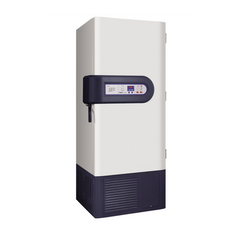
Page 7: Product Appearance
Product appearance DW‐86L388/486/628/728/828 7 / 88 ... - Page 8 DW‐86L288 DW‐86L338/388A 8 / 88 ...
- Page 9 DW‐86L490 DW‐86W100 9 / 88 ...
- Page 10 DW‐86W420 10 / 88 ...
- Page 11 Dimensions DW-86W100 11 / 88 ...
- Page 12 DW-86L490 12 / 88 ...
- Page 13 Other Modles 13 / 88 ...
-
Page 14: Parts Layout
Parts layout Locked Buzzer cancel Low temp High temp network alarm alarm Run Sensor failure regulator Low battery Condenser dirty High ambient temperature Back system Power failue Improper ... - Page 15 Main s senser: The f fixed cover of the main senso r in the box Stainle ess steel Inner colo or: Cream yel llow shelvin ng fixed clam mp Material: electro‐galva anized steel shee et ox beams deco orated bar Inner door h handle: replace dism mantled handle the c center of rotation of th he screw Cabinet mou uth ...
- Page 16 Test hole CO2 backup s system Senser hole Cabin guard p plate Power code Door h inge (under) Batte ry swtich Powe r swtich The ca bin right guar rd Name eplate and serial numb ber The ca abin left guar rd 16 / 88 ...
-
Page 17: Electronic Structure
Remote Elec ctrical control box alarm R232/4 485 serial wiring port m module ain control boa Low tem mperature pressuriz zed AC contac ctor Battery y Switch The high h temperature e Buck AC contactor Switch Transform mer Wiring board Relay Condense er Conden nser Batte ery ... - Page 18 Mother Board High temperature Condensation Standby Pressure compressor decrease Induced draft temperature Pressure compressor increase 18 / 88 ...
- Page 19 Master sensor Voltage Network Display Temperature adjustment connection panel regulation Screw connection screw Mother Board Heat exchanger sensor Condenser sensor Computer panel test key: under the condition of power ON, press down the test key and see if all relay lamps are lighting in continuous cycle, otherwise, check if the relays that are not lighting ...
-
Page 20: System Architecture
Compressor: look from the back Anti‐dew tube The left: High temperature stage The right: Low Temperature stage High temperature condenser Condenser fan High-stage gas-liquid separator Oil separator High‐temperature filter Low Temperature pressure control Low‐temperature valve filter 20 / 88 ... -
Page 21: Cooling Unit Parts
DW‐86L338/388A / Ф9.52X0.75 gas‐liquid separator All the ULT‐freezer 0.130XФ60X1.2 / M4Q045-CA03-51, AC230V/50/60Hz, 36/34W Fan motor All the ULT‐freezer Display panel All the ULT‐freezer Haier HY‐DLB PCB‐220V/120V Control board All the ULT‐freezer Haier HY‐DLB PCB‐220V/120V Danfoss DML 083S Dry‐filter All the ULT‐freezer gas‐liquid separator All the ULT‐freezer / Temprite 900G ... -
Page 22: Refrigeration Circuits
Refrigeration circuits Diagram of refrigerating system Dry filter Capillary tube Dry filter Evaporator Heat exchanger Capillary tube Gas-liquid separator Condenser High temperature temperature compressor compressor Pressure control Valve Oil separator 22 / 88 ... -
Page 23: Circuit Diagram
Circuit diagram Mother board Bottom Test-P oint Bottom Test-Point Display panel 23 / 88 ... - Page 24 Display Rechargeable board battery Heat prober Power panel Heat prober Booster 24 / 88 ...
-
Page 25: Connections On Main Pcb
Connections on Main PCB Connector Connect to Usage CN1 wiring board Power supply Compressor realy Control compressor battery Battery power Main sensor Main sensor Two fans and heater Control fans and heater Condenser sensor Condenser sensor Heat exchanger sensor Heat exchanger sensor For display panel backup CN10 For display panel backup CN12 AC cantactor Control the voltage ... -
Page 26: Specifications Of Sensor
Specifications of sensor temperature Resistance temperature Resistance temperature Resistance temperature Resistance KΩ KΩ KΩ KΩ ‐40 63.3 ‐19 17.8 2 5.8 23 2.1 ‐39 59.4 ‐18 16.8 3 5.5 24 2.0 ‐38 ... -
Page 27: The Value Of The Probe Resistance Varies With Temperature (Probe Type: Pt100)
temperature Resistance temperature Resistance temperature Resistance temperature Resistance KΩ KΩ KΩ KΩ ‐130 48 ‐80 68.3 ‐30 88.2 20 107.8 ‐120 52.1 ‐70 72.3 ‐20 92.2 30 111.7 ‐110 56.2 ‐60 76.3 ... -
Page 28: Detailed Technical Data Of The Product
Detailed technical data of the product Overall dimensions Inner dimensions Effective Input Compre Inner Type Rated voltage (depth*width*height) (depth*width*height) volume(L) power(W) ssor door (mm) (mm) DW‐86 L288/28 288/286L 220V50Hz 930W 1641*915*870 971*620*550 SC21CL 3 6 DW‐86 L388/38 388/386L 220V50Hz 1000W 1980*915*870 1310*620*550 ... -
Page 29: Product Nameplate
product nameplate For example: DW‐86L338 29 / 88 ... -
Page 30: Transportation And Installation
Transportation and Installation 1.1 Transportation: the product is heavy, so fork or hydraulic jack will be used during transportation, to avoid damaging the personnel and product. 1.2 Removal of package: packing method of the product: wooden support+EPE During transportation, the fork or hydraulic jack is required to insert into the bottom of the wooden support to transport the product. Packing scheme is shown as the following figure: Notes: Removal of packing refers to “Single Page for Removal” sticked to the inside of packing carton. Please note that the connecting pieces front and rear must be removed before the wooden ... -
Page 31: The Product Enters The Placement Room
Figure 1: Connecting pieces of the wooden base Figure 2 Fastening pieces of low temperature cabinet 2.1 It is difficult to enter the door: if the product can’t enter the room height required by the client and its access is unavailable without the bottom base, the front cover of the cabinet can be removed and open the door to 180 degree. Removal of the front cap of cabinet and the notes for attention are shown as: Notes: In general, we don’t recommend removing the front cap of cabinet. 2.2 Remove two screws below the front cap of cabinet. Remove the front cap. ... -
Page 32: Product Installation And Matters Needing Attention
... - Page 33 Height of the working position of the equipment: less than 2000m Operating humidity: less than80%RH. If the maximum operating temperature is 32 the humidity shall be less than 57%RH. Input voltage: Within 220±10%. Notes: Because the ultralow equipment is sensitive to the ambient temperature, if the machine can’t operate normally if it is installed in the environment other than the above ones, then it can be applied again after the environment is improved. 3.2 Matters needing attention of the product At least a 20cm clearance shall be reserved between the wall and the back of equipment Ground of the installation site must be level, whose ambient temperature shall not exceed 30 . The equipment shall be applied under an environment of 25 . If the temperature is too high, then the air conditioner is required for solution. Fix the machine well with fixed bolts. Good ventilation indoor. Don't’ use the same socket with the plug of other equipment, the plug and socket must be connected securely. Please note that the power line shall not be twisted or pressed. If the wire shall be lengthened, standard of the feeder line will be 230V and 15A, and the lengthened part shall not exceed 3m. The equipment is especially used for 208~230V 50/60Hz power. Please check the operating voltage before use, if it is lower than 180V, then the transformer will be used to boost, and the ...
- Page 34 underground.( burial depth is 25cm at least). Notes: The earth wire shall not be connected to the gas pipe, telephone line or lighting line. 3.3 Method of application after completion of installation For the ultralow temperature cabinet firstly used, or after the ultralow temperature cabinet is handled, or the ultralow temperature cabinet experiences power failure (including outage) for more than 10 hours, then the equipment must be verified before use (or before energization) . The verification shall confirm that The equipment shall be energized only after the refrigerator has been rested for more than 24h. The articles shall not be put in the empty cabinet. Turn on it after energization, and then cool it by stages. Firstly cool it to ‐40 , then to ‐60 after normal startup and shutdown. Then cool to ‐80 8 hours after its normal startup and shutdown. Observe the refrigerator for ...
-
Page 35: Specifications Of Lcd Panel
Specifications of LCD panel For adjusting the setting values, firstly they must be unlocked. Press “ ”or” ”, temperature setting values will flash, press “ ”or” ”, and input the number 06, then hold “Function Selection” for 5 seconds, “Lock” lamp goes out, to enter unlock status. After that the settings as follows can be done, press “Function Selection” to repeatedly choose temperature set, high temperature alarm set and low temperature alarm set inside the refrigerator, and the corresponding indicating lamps will be lighten. 1 2 3 For “Temperature Set”, the display area will flash, to display the temperature setting value. At this time, press “ ” and “ ” to change the setting values. If no operation is done within 10 seconds after adjustment, then it will enter locking status automatically. If temperature display flashing stops, it shows that the values have been input to the computer, otherwise they are invalid. Temperature ... -
Page 36: High Temperature Alarm
When set “High Temperature Alarm”, if temperature set display area flashes, it indicates the temperature setting value, at this time press shifting and adjusting key to adjust the alarm setting value. If no operation is done within 10 seconds after adjustment, then it will enter locking status automatically. If temperature display flashing stops, it indicates that the values have been input to the computer, otherwise they are invalid. The temperature set shall not exceed the maximum limit temperature or be less than the setting temperature by +5 when setting the high temperature When setting “Low Temperature Alarm”, if setting temperature display area flashes, it indicates that the temperature setting values. At this time, press “ ”and “ ”to adjust the alarm setting value. If no operation is done within 10 seconds after adjustment, then it will enter locking status ... -
Page 37: Indicating Of Working Status Of Display Panel
Indicating of working status of display panel 1. The refrigerator will enter starting status after it is switched on, and all parameters on the display screen will be saved as those before the last power interruption. The displayer will display the actual temperature, setting temperature and current voltage. Indication of working status of the display panel: “Lock” indicating lamp: if the lamp lights, indicating all settings are locked, to prevent misoperation. “Network” lamp: if it lights, indicating the network system has been in operating status. “Operating” lamp: if it lights, indicating the compressor is operating. “Stabilization” lamp: if it lights, indicating the voltage booster is boosting or reducing the voltage. 115V When the refrigerator is applied to 115V circuit, when the input voltage drops to 98V, the booster will be connected to boost. When the input voltage increases to 113V, the booster will be disconnected, with boosting amplitude 12V; when the input voltage increases to 125V, the booster will be connected to reduce voltage. When the input voltage ... -
Page 38: Indication Of Alarm Status
Indication of alarm status “High temperature” indicating lamp: if the lamp lights, indicating the alarm display when the temperature inside the refrigerator is higher than the setting value. “Low temperature” indicating lamp: if the lamp lights, indicating the alarm display when the temperature inside the refrigerator is lower than the setting value. “Over voltage” lamp lights, indicating the voltage is lower than 184V (95V) or higher than 253V (136V), buzzing. ... - Page 39 ambient temperature, when the ambient temperature exceeds 38 (excluding 38 ), “too high ambient temperature” indicating lamp in the alarm display area will light and send alarm, accompanied with buzzer alarm. Light flashing alarm can’t be cancelled, until the fault is removed. While the buzzer audible alarm can be silent when press “buzzing cancel”, with mute period of 30 minutes. 30 minutes later, the buzzer audible alarm will ...
-
Page 40: Setting Of Special Functions
Setting of special functions When the low temperature refrigerator is firstly used, unlock password is 06. After unlocking, press “Function Selection” and “Buzzer Cancel” for 5 seconds simultaneously, 06 will be displayed on the display, then press “▲” and “▼”to adjust the password values. Password value can be chosen among 05, 06, 07……29, 30. No operation will be done within 5 seconds after the password value is set, then it will enter the lock status automatically, indicating the password value set is valid. When unlock the password value, ... -
Page 41: Requirements Of Battery Control
two fans will be turned off. There is a battery power switch on the equipment, which will be turned on before normal start. The equipment will enter normal operating status only it is connected to AC power satisfying the equipment requirement. When AC power can provide the normal power supply, the equipment can charge the battery as required. When AC power is interrupted due to accident, the battery can supply the display screen, to realize normal display. When the battery discharge is less than or equals 10.5V, then the battery will stop supplying the display screen, without any display. If the power will be completely disconnected when the battery can provide the normal power, it only needs to pull out AC power wire and shut off the battery on equipment, and nothing will be displayed on the display screen. ... -
Page 42: Precautions
display fault on the display screen is E5. Alternate display time: the actual temperature display is 6 seconds and fault code display is 2 seconds (since Nov. 2009). 7.1 After initial installation or moving equipment, clockwise rotation of the horizontal leg horizontal feet support the ground to ensure that the freezer does not move when you use need to stand for 24 hours after the power use after you install the fixed place 7.2 The room temperature should be kept below 28 (If the ambient temperature is higher than 32, the cooling efficiency will decline rapidly, and ambient temperature for a long time is higher than 32 may result in compressor damage or reduced life, therefore, to use the product environment is recommended to install air conditioning) 7.3 Single piece of equipment should be independent and use a socket and power socket withstand current should be greater than 16A, and reliable ground 7.4 Energized when you first open the battery switch on the machine electrical control box, take a long time to shut down the power to turn off this switch. 7.5 The cryogenic refrigerator door every time the time to try to not more than 1 minute, before closing the door seals on the ice water to wipe clean to ensure good sealing effect. ... -
Page 43: Fault Code
ault cod rception co ondenser te mperature minus amb bient tempe erature diffe erence ≥ 13 3 ° C (for five e minu utes), the c ondenser is s dirty "ind dicator light t, and acco ompanied b by a buzzer r alarm, the e initia l on electric city within t two hours, t the indicato or and buzz er not alarm m ... - Page 44 Conden nser probe Type: N hen the ri ng temper rature sens sor failure, the displa ay alternat tely shows the actua al temp perature an d the main sensor faul t code "E0" ". Prob e Type NTC hen heat ex xchanger se ensor failure e, sensor fa ault code in ...
- Page 45 The heat exchanger sensor probes foam box inside of the bottom Heat exchanger sensor terminal When , heat exchanger sensor senses the temperature ≥ 90 alarm display Remarks: (Model ‐25 ° C and ‐50 heat exchanger sensor so no E3, E4, fault) (Model: independent backup system no E0, E1, E3, E4 fault) Alternately display time: the actual temperature display 6 seconds, the fault code is displayed for 2 seconds. ...
-
Page 46: Product Use And Maintenance
Product use and maintenance The design of overlaying‐type freezing medium system is used for freezing mediums with different boiling points; this system needs two independent cooling systems. It is shown as above, each system can work synchronously; first level system is used for the high temperature section of second level cooling. Second level is the main system, which is used to maintain the temperature in low temperature cabinet. Freezing medium is compressed by first level compressor ... -
Page 47: Pressure Switch And Infusion Of Freezing Medium
hours prior to use (or powered up again before use) inspection machine. Qualified to confirm the testing machine The use of the cryogenic cabinet 1) Must stand for the freezer for at least 24 hours to energize. 2) empty containers not put items power on in stages so that the freezer before cooling to ‐40 ° C the normal open stop and then dropped to ‐60 degrees, normally open to stop eight hours and then transferred to ‐80 degrees, observed freezer there are normally open to stop more than 24 hours. Prove freezer performance is normal. 3) Press operation after 2 confirm the freezer normal freezers memory to place items. ‐60 ... - Page 48 decreases to 1.35MPa, contact connects, low temperature cabinet starts up; when pressure exceeds 2.1MPa again, contact disconnects again, and it circulates in order. Note: When pressure switch is being welded, put a wet towel on it to keep temperature below 100 . The parameters of pressure switch cannot be adjusted. Parameters: voltage 220V, 50Hz, contact capacity: 6A. Freezing medium Freezing medium is mixture, part of it is inflammable and explosive freezing medium, ventilation is required at infusion place. In case of leakage, avoid fire and spark near the place. When refrigerating system has a problem, it shall be judged by local after‐sale service ...
- Page 49 the systems. For the machine that its system has already been opened, the pipe welding shall be finished at once. As the machines have strict requirement for system moisture content, so, when a machines pipe is opened, the opening of pipe shall be sealed with tape at once to prevent air from entering in system, and pipe welding of opening shall be finished within 20 minutes. As the system of DW‐86L386 series of ultra‐low temperature cabinet products has very strict ...
-
Page 50: Fan Parameters
Product model SL‐490C2W Parameter Special No. / / Fan application Evaporation fan Condensation fan Manufacturer EBM EBM Fan model / / Rated voltage 230V 230V Input power 10W 10W Fan type Induced draft type Induced draft type Dimension Fan blade diameter 200 Fan blade diameter 230 50 / 88 ... -
Page 51: Gas Collection And Charge
Gas collection and charge High temperature level compressor Low temperature level compressor Oil separator Condensation fan Product model DW‐86L386/288/388, DW‐86W420 Compressor model SC21CL Voltage range(V) 208~230 Refrigerating 3/4 HP Rated frequency(Hz) 50 output(W) Input power(W) 800W ... -
Page 52: The Characteristics Of The Refrigerant
1) Refrigerant mixed working quality, some flammable, explosive refrigerant perfusion spaces should be ventilated, once the leak, not in the vicinity of the ignition or sparking. Refrigeration system problems, feedback issues point by the local aftermarket judgment and guidance of the local after‐sales maintenance, depending on the situation by the Medical Division technical staff. ... - Page 53 open, and let go of the refrigerant in the system. 2) in the system, the opening 20 minutes, the open pipe with a pressure gauge welding is completed Note 1) This model is a two refrigeration, sub‐high temperature and low temperature level, two separate sets of system maintenance, do not avoid two systems at the same time to open, must understand that the open set of system 2) the maintenance shop humidity can not be too large, in case of cloudy rainy weather, prohibiting the opening of the system, should immediately open system machine pipe welding completed ...
- Page 54 high h pressur e the tim e and qu ickly high tempera ture perf usion tub be welding g ling mach hine refrig geration h high press sure (refri igerant pr ressure is too high , n not seal the mout th), low pr ressure co ontinues t...
- Page 55 PICTURE 2 PICTURE 3 3Pa Unit: Pa PICTURE 4 55 / 88 ...
- Page 56 Perfusion refrigerant high temperature level perfusion, the machine should be in a stopped state before perfusion R134A refrigerant and then perfusion R404A refrigerant. Perfusion was performed in accordance with the attached table! Note 1) To ensure the refrigerant once reperfusion in place, the above refrigerant is required when the cylinder is inverted perfusion liquid perfusion in Figure 5 2) Low‐level refrigerant reperfusion, the same machine should be in a stopped state, first perfusion HRA refrigerant, then perfusion HRB refrigerant, because of higher the HRB refrigerant pressure. Perfusion was performed in accordance with the attached table! Irrigation after the infusion process tube sealing, sealing effect is shown in Figure 6 ...
- Page 57 refrigerant necessary, using the above export perfusion, the above infusion refrigerant cylinders upright perfusion, the perfusion gas. 4) In order to ensure the accuracy of refrigerant perfusion, perfusion of all refrigerant necessary electronic weighing scales perfusion. 5) Evacuation and refrigerant perfusion is not in accordance with the above requirements and operating process execution lead to machines refrigeration poor or no refrigeration, and returned machine outlets. ...
-
Page 58: Infusion Flow Of Freezing Medium
PICTURE 6 The schematic diagram of each freezing medium cylinder Infusion flow of freezing medium When infusing high temperature level freezing medium, machine shall be under the status of stop, firstly, infuse R134Afreezing medium, then infuse R404Afreezing medium; to ensure that freezing medium can be infused successfully at one time, at the time of infusing above freezing mediums, cylinders must be placed upside down to infuse liquid. As the infusion quantity of low temperature level freezing medium is small, and the requirement for the infusion quantity of freezing medium is very strict, if infusion quantity is ... - Page 59 medium, at the time of infusion, you must turn on cylinder valve a little to avoid wasting freezing medium and affecting maintenance progress. When infusing low temperature level freezing medium, machine shall also be under the status of stop, firstly, infuse HRA freezing medium, then infuse HRB freezing medium; as HRB freezing medium has very high pressure, ordinary cylinders cannot bear very high pressure, so oxygen cylinders are used to contain HRB freezing medium; at the time of using, the exit at the bottom of cylinder must be plugged up with a screw to prevent freezing medium from leaking. ...
-
Page 60: Refrigerant Perfusion Details
The refrigerant (type / Type The refrigerant (type / amount) 2 amount) 1 Improved date R134A g R404A g R508B g R290 g R23 g DW-86W100 DW-86W420 DW-86L288/286 DW-86L338 DW-86L386 DW-86L388 DW-86L486 DW-86L490 DW-86L626/628 DW-86L728 DW-86L828 DW-86W420 2012.4.1 (old type) DW-86L288 2011.1.10... -
Page 61: Troubleshooting
Troubleshooting Fault Analysis Maintenance Measures 1. User’s fuse burns out Change the fuse 2. Machine storehouse wiring connector plugs s are Change the connector plugs damaged Check contact and make in good 3. Bas wire contact condition. 1.High temperature level Checking if it is due to bad 4. - Page 62 Fault Analysis Maintenance Measures Change the location of the 1. Uneven placement freezing cabinet. Clear up pipeline or add a shock pad under compressor 2. When compressor is running, there is resonance baseboard 6.Freezing cabinet noise is between pipeline and cabinet. high To avoid resonance.
- Page 63 Fault Analysis Maintenance Measures 1. The user's test instrument is not accurate Change the test instrument under locked state press down "temperature" button until temperature calibration value 2. Temperature probe of sensor is not accurate displays flickeringly on the displaying 8.
- Page 64 1.E0 alarm Ring temperature sensor input voltage 1.Check the ambient temperature sensor terminal plug bad or ≥ 4.9V, the sensor open; ≤ 0.1V, the falling; sensor for damage short‐circuit 2 Check the display board sensor connector terminals are loose or poor contact; whether the display panel damage 2.E1 alarm When the condenser sensor input 1.Check the ambient temperature sensor terminal plug bad or voltage ...
-
Page 65: How To Deal With High Temperature Alarm
How to deal with High temperature alarm Refrigerator temperature ≥ high temperature alarm set temperature (high temperature alarm set temperature ≥ run set temperature +5 ° C) Check the display board LED High temperature alarm lights and control circuit Lights flashing Check the control panel After 15 minutes flashing buzzer and control circuits alarm, sound alarm Test Input voltage display is Check the power is normal normal Check the compressor and Low‐temperature stage control circuit ... -
Page 66: How To Deal With Low Temperature Alarm
How to deal with Low temperature alarm Refrigerator temperature ≥ high temperature alarm set temperature (high temperature alarm set temperature ≥ run set temperature +5 ° Check the display board Low temperature alarm Lights LED lights and control flashing circuit ... -
Page 67: Points Needing Attention During Normal Use Of The Product
Points needing to pay attention ●When the refrigerator is firstly used or the storage box hasn’t been used for a long time, the alarm “Low battery” will appear, because the charged battery has been completely discharged. But it doesn’t mean that there is a fault. In this case, the empty battery will be charged adequately, to make the storage box to continuously run for about 6 days. ●When the storage box runs, areas around the door frame of the outside case of the refrigerator ... - Page 68 inner door of the refrigerator body. If it is too thick, freezing effect of the storage box will be influenced, to increase the power consumption. Therefore, when the frost layer reaches 5mm thick, it shall be removed with the shovel attached at intervals. ●Prior to defrosting, please take out the articles from the box and put them into another one for freezing, to avoid damaging the articles due to temperature rise inside the storage box. ●There are many cooling coils on the back of inner wall and the side, don’t remove the frost on inner wall with knife, ice chisel or screwdriver. During defrosting, the inner wall shall not be scratched; otherwise it will produce the equipment fault. ●When the storage box hasn’t been used for a long time, the power shall be shut off and the battery switch shall be switched off at the same time. ...
-
Page 69: Points Needing Attention During Normal Use-Safety Requirement
Please apply the special power (AC220V‐/50Hz) marked on the equipment nameplate. If the voltage applied is less than 198V or higher than 242V, the automatic stabilizer exceeding 4000W shall be provided. If the power wire needs to be lengthened, section and length of the lengthened part shall not be less than 2mm2 and greater than 3m respectively. Application of the power with other voltage or frequency which isn’t marked on the nameplate will possibly cause fire or electric shock. Power wire of the storage box is equipped with 3‐wire (earthing) plug, meeting 16A standard 3‐wire (earthing) socket. Under no circumstances, earthing pins of the power wire shall not be cut off or removed. Plug and socket of the power wire must be guaranteed to be connected securely, otherwise it will produce fire. The power socket with earth wire shall be used, to avoid electric shock. If the power socket isn’t ... - Page 70 explosion or fire. The corrosive articles such as acid and alkali shall not be stored in the equipment; otherwise its inner components or electric parts will be damaged. The metal object such as iron nail or iron wire shall not be inserted into any port or clearance of this equipment, or any exhaust port for inner air circulation, otherwise the electric shock or damage will be produced due to the contact between above object and running part. When the equipment is used to store the poison, harmful or radioactive articles, it shall be used in the safe area. Otherwise it will cause personal injury or environmental harm due to improper use. When the inflammable gas such as gas leaks, the leakage valve shall be shut off. Then open the doors and windows for ventilation and exhaust. Don’t pull out or insert the power plug of the storage box. The equipment power shall be disconnected prior to its any repair or maintenance, to avoid electric shock or personal injury. ...
- Page 71 equipment damage will be caused due to equipment turnover. Close the box door with your hand holding the handle, to avoid the fingers being clamped. Don’t put the glass bottle or canned goods into the box, since personal injury will be caused due to their frost cracking. Don’t touch the goods stored. Direct touch of the freezing articles or inner wall of the equipment may produce cold injury. The gloves shall be worn during repair, to avoid damaging the hands by the sharp edge or corner. ...
- Page 72 later, so as not to damage the compressor or system. The power plug must be pulled out during maintenance. Don’t roll or damage the power wire. Disposal of the discarded equipment must be carried out by the relative personnel. The box door shall be dismantled, to avoid the accidents such as suffocation. ...
-
Page 73: Points Needing Attention During Normal Use-Disposal Of Special Circumstances
If the equipment has any fault, please check the following faulty points before maintenance: The equipment can’t be started ●Check the power is normally connected or the mains switch is switched on or not? ●Is the voltage is too low? ●Is there too much articles stored in the storage box one time? Bad cooling ●Is the ambient temperature too high? ●The inside and the outside door are opened tightly? (Frost between the box body and the door seal will damage the sealing of door). ●Is the filter net of the condenser blocked by dirt? ●Is the temperature setting is correct? ●Is the storage box far away the direct sunshine? ●Is the storage box close to heat source? ●Are the rubber cover and heat insulating material used by the testing through hole placed correctly? ●Is there too much unfrozen articles placed in the storage box within several hours? (Under this case, ... - Page 74 hence the equipment temperature shall be reduced by steps, to avoid too much temperature reduction within a short time. Warning In order to prevent electric shock or personal injury, the equipment shall be disconnected from the power prior to any repair or maintenance. Ensure that the chemicals or suspended particles around the equipment shall not be absorbed during maintenance; otherwise it will endanger your health. ...
-
Page 75: Other Maintenance And Repair
Other maintenance and repair Storage box shall be cleaned once a month. Regular cleaning can make storage box keep clean appearance. Use a dry cloth to wipe off dirt on box shell, inner chamber, and all attached bodies. If storage box is very dirty, dip a clean cloth into neutral detergent and remove dirt, and then use a wet cloth to remove residual detergent; at last, use a dry cloth to wipe dry. (Undiluted detergent may damage plastic parts, please refer to the instructions for diluting detergent. Don’t pour water on storage box shell or in storage chamber, otherwise, electrical insulation may be damaged, which may cause failure. Compressor and other mechanical parts are under totally‐seal state, they need not to be lubricated. Frost or ice on inner wall shall be removed once a month; condenser filter screen shall also be cleaned once a month. When “condenser is dirty” alarm lamp on storage box display panel is flashing, filter screen needs to be cleaned. Even the lamp is not flashing; filter screen shall be cleaned once a month. ... -
Page 76: Defrost Inner Wall
Generally, frost occurs on the upper part of refrigerator body and inner door. Frost may cause gap between refrigerator body and door sealing strip, which may cause bad refrigerating effect. Defrost on inner door with a defrosting shovel, which is provided together with the equipment. Empty refrigerator body, and then defrost according to the following method: Note: Don’t defrost with the tools that have sharp edge and corner, for example, a knife or a screw driver. 1. Take out objects in refrigerator and put them into another storage box, or a container with freezing liquid‐state carbon dioxide. 2. If there is an aided cooling device, turn off the device. 3. Turn off the power. 4. Open outer door and inner door, let refrigerator outer door naturally open for a period of time to melt frost. 5. Use a dry cloth to wipe off the water on refrigerator bottom. ... - Page 77 storage may be affected. It is suggested that the battery shall be replaced as soon as possible. If you need to replace battery, please contact Haier after‐sale service personnel. Warning: To avoid electric shock or personal injury, before equipment maintenance or repair, the power must be cut off. When maintaining the equipment, make sure not to breathe in drugs or suspended particulates around the equipment, which may be harmful to your health. ...
-
Page 78: Faq
Question: Displayed temperature is not the same as actual test temperature: Answer: As the displayed temperature is the temperature at one point in refrigerator, while a user is testing the temperature of another point in refrigerator, as position is different, temperature must be different, meanwhile, the user’s testing tool may have certain measurement error with our temperature detector. Question: The temperature difference between upper part and lower part in refrigerator is too large: Answer: As our machines start refrigerating from up to down, the upper part temperature is lower than lower part, meanwhile, the temperature difference is large. The temperature difference ... -
Page 79: Alarm Of Battery Low Electric Quantity
Question: Why is it displaying E0 and other signs? Answer: Main sensor failure: E2 condenser sensor failure:E1, ambient temperature sensor failure:E0, check if above wiring is normal or not, if is not normal, please contact after‐sale service personnel for maintenance or replacement. Question: If the machine is moving when I open its doors, what shall I do? Answer: Our machines have casters, which are flexible, moveable, lockable, and supportable, and can be slightly adjusted according to request. After a machine is installed on the position appointed by a user, the two front casters shall be fixed to prevent the machine from moving when its doors are opened. Question: Why the door of low temperature cabinet can not be opened? ... -
Page 80: Alarm Of Dirty Condenser
6, it shall be over 7.5V) so model machine computer panel can recharge battery; if battery electric quantity is lower than 10.5(for old products with mode of 6, when it is lower than 7.5V), a machine starts to recharge the battery, it takes about 5 days to finish recharging battery; if the machine still meets the problem of battery alarm, the battery needs to be replaced. When the machine is not used, battery switch must be turned off, otherwise, after ... -
Page 81: Used Spare Parts Photo Gallery
Used Spare Parts Photo Gallery DW-86L628 Whether Sn Part code Spares Name picture wearing parts 1 0070701061 Filter dryer 1 pressure control switch for 2 0070700606 1 2nd stage 3 0070701865 Suction accumulator 1 4 0270200538 Outer gasket for outer door 1 Y 5 0270200322B ... - Page 82 7 0070101872 duplex all‐round caster 1 8 0074091318 Display board 1 Y Condenser temperature 9 0074091225 1 sensor 10 0074090884 Ambient sensor 1 Y 11 0070204295 Cover for access port 1 12 0070204827 Inner door handle 1 Y 13 / Defrost shovel 1 ...
- Page 83 Outer gasket for inner door 14 0270800385 1 Y (Interior door assembly) Inner gasket for inner door 16 0270800385 1 Y (Interior door assembly) 17 0070401235 Battery power switch 1 Y 18 0070106373 Inner door hinge 1 Y 19 0070107087 Outer door hinge 2 Y 20 0070107112 Outer door handle 1 Rechargeable battery of 21 ...
- Page 84 22 00707 700552 Oil sep arator 1 Cabinet tem mperature 23 00740 091183 control sensor 4 100 24 02707 700027 Air cooled c condenser 1 Door switch for backup 25 / 1 Y system c control 26 00740 090871 AC contactor ...
- Page 85 Power re elay for 30 00240 000070 1 Y compressor( 220V/60Hz) Catch assem bly for latch 31 00708 815591 1 Y mecha anism 32 00740 090752 Circuit b breaker 1 ...
-
Page 86: Testing Date
Testing Date Cooling Rate Ambient temp The third floor center temperature Cooling Rate SN Model Power supply Ambient temp Cooling time(from ambient temp to ‐80 )min 1 DW‐86L288 220‐240V/50Hz 360 2 DW‐86L388 220‐240V/50Hz 420 220‐240V/50Hz 3 DW‐86L486 208‐230V /60Hz 420 115V60Hz 220‐240V/50Hz 4 DW‐86L628 208‐230V /60Hz 450 115V60Hz 220‐240V/50Hz 5 DW‐86L728 480 208‐230V /60Hz ... - Page 87 Temperature of the cooling system parts Temperature of the parts Cooling system temperature Ambient sn model Power supply temp H‐IN H‐OUT L‐IN E‐IN E‐OUT 1 DW‐86L288 220‐240V/50Hz 2 DW‐86L388 220‐240V/50Hz 220‐240V/50Hz 3 DW‐86L486 208‐230V /60Hz 115V60Hz 220‐240V/50Hz 4 DW‐86L628 208‐230V /60Hz 115V60Hz 220‐240V/50Hz 5 DW‐86L728 208‐230V /60Hz ...
- Page 88 Inspired living Haier Medical & Laboratory Products Co., Ltd. Room 403D, Brand Building, Haier Industrial Park, No.1 Haier Road Qingdao China Website: www.haiermedical.com ...
Need help?
Do you have a question about the DW-86L288 and is the answer not in the manual?
Questions and answers
El compresor no arranca, no está dañado, que puede ser ?