GE Spacemaker WSM2780 Installation Instructions Manual
Gas
Hide thumbs
Also See for Spacemaker WSM2780:
- Use and care manual (24 pages) ,
- Installation instructions manual (9 pages) ,
- Installation instructions manual (9 pages)
Table of Contents
Advertisement
Quick Links
WARNING-
POTENTIAL
FIRE AND SHOCK
HAZARD
•
Use only rigid metal or flexible metal 4" diameter
ductwork inside the dryer cabinet or for exhausting
to the outside.
Use of plastic or other combustible
ductwork
can cause a fire. Foil or other
easily
punctured ductwork can cause a fire if it collapses or becomes restricted in use or during installation.
• This appliance must be properly grounded and installed as described in these instructions.
Important
•
Exhausting
the dryer to the outside is required
to prevent
large amounts
of moisture,
lint and other products of
combustion
from being blown into the room.
•
Service information
and wiring diagram
located in dryer
access panel.
Tools
Required
Slip joint pliers
Phillips
head and flat blade screwdrivers
Ratchet
with 3/8" socket
Carpenter's
level
Adjustable
wrenches
Pipe thread
sealer
Contents:
PROCEDURE-
Page
2
--
Page 4
--
Page
5
--
Page
5
INFORMATION
--
Page
6
--
Page
6
--
Page
7
MISCELLANEOUS
--
Page
7
INSIDE
--
Page
7
31-1832
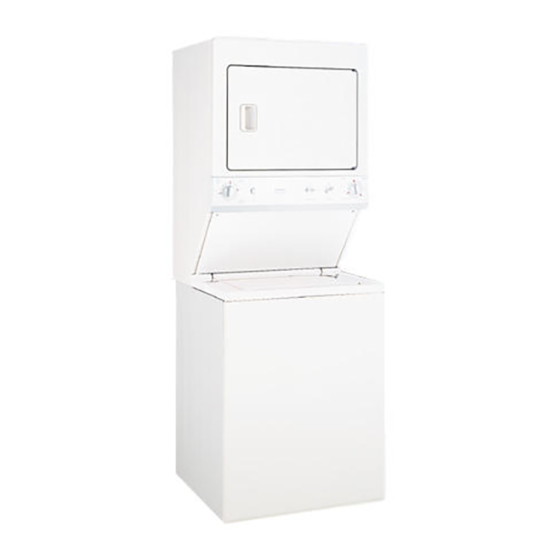
Product Dimensions
®
®
___m
3 3/1"
s S_JPP_. _
--
43"
l
41
29
7/16*
I/IS"
Advertisement
Table of Contents

Related Manuals for GE Spacemaker WSM2780


Summary of Contents for GE Spacemaker WSM2780
-
Page 1: Table Of Contents
WARNING- POTENTIAL FIRE AND SHOCK HAZARD • Use only rigid metal or flexible metal 4" diameter ductwork inside the dryer cabinet or for exhausting to the outside. Use of plastic or other combustible ductwork can cause a fire. Foil or other easily punctured ductwork can cause a fire if it collapses or becomes restricted in use or during installation. - Page 2 INSTALLATION (cont.) NOTE: The tub blocking pad, shipping bolt and Installation plastic spacer should be retained for use if the Unpacking Spacemaker appliance is transported at a later date. STEP l -- Remove tape and two comer pads STEP 8 -- Remove clips holding the following: from rear bottom comers...
- Page 3 INSTALLATION (cont.) INSTALLATION (cont.) Connecting to Plumbing Facilities: STEP 14B-- Ensure the shutoff valve handle the dryer is open. CAUTION: Be sure water supply lines have been thoroughly flushed to remove particles that STEP 14C m Open the shutoff valve in the gas supply line.
-
Page 4: Installation
INSTALLATION (cont.) PlumbingInformation Final Appliance Leveling: CAUTION: ALL WEIGHT MUST BE Water Supply Requirements REMOVED FROM APPLIANCE LEVELING • HOT COLD WATER FAUCETS must LEG WHILE ADJUSTING. THREADS be within 42" of the appliance water inlet LEG WILL BE DAMAGED OTHERWISE. -
Page 5: Electrical
(cont.) I_LI_J INIIJAL ElectricalConnection Information • Installation must meet American National Standard, National Fuel Code ANSI Caution,For PersonalSafety: 223.1--1988 and local codes and ordinances. TURN ELECTRICITY AT POWER • The gas supply line should be 1/2" pipe. A 1/2" SOURCE (CIRCUIT BREAKER / FUSE... -
Page 6: Exhaust
EXHAUST (cont.) EXHAUST (cont.) Sealing of Joints Exhaust Duct Length Information • All joints should be tight to avoid leaks. • The MAXIMUM ALLOWABLE length of the exhaust system depends upon the type of NOTE: The male end of each section of duct duct, number of turns, the type of exhaust must point away from the dryer. -
Page 7: Alcove & Closet Installation
Alcove or Closet Installation Door Ventilation Opening A minimum of 120 square inches of opening, equally divided at top and bottom is required. openings are required to be unobstructed when a door is installed. A louvered door with equivalent SQ. IN. air openings for the full length of door...
Need help?
Do you have a question about the Spacemaker WSM2780 and is the answer not in the manual?
Questions and answers