
Subscribe to Our Youtube Channel
Related Manuals for Garmin Sounder GPSMAP 135


Summary of Contents for Garmin Sounder GPSMAP 135
- Page 1 OWNER’S MANUAL AND REFERENCE ZOOM ZOOM ZOOM OPTION MENU EDIT ENTER GPSMAP 135 Sounder ®...
- Page 2 GARMIN. Information in this document is subject to change without notice. GARMIN reserves the right to change or improve its products and to make changes in the content without oblig- ation to notify any person or organization of such changes or improvements.
-
Page 3: Warning
Warning The GPSMAP 135 Sounder should not be used as a navigational aid or depth sounder to prevent collision, grounding, boat damage, or personal injury. The digital depth displayed is the depth under the back of your boat and not the front. By the time a depth is displayed most of your boat has already passed over that area. - Page 4 (NAVAID), any NAVAID can be misused or misinterpreted and, therefore, become unsafe. Use the GPSMAP 135 Sounder at your own risk. To reduce the risk of unsafe operation, carefully review and understand all aspects of this Owner’s Manual—and thoroughly practice operation using the simulator mode prior to actual use. When in...
- Page 5 Designed for detailed electronic charting and complete depth sounding capabil- ity, the GARMIN GPSMAP 135 Sounder is a powerful navigation device that can also give you the fishfinding information you need in fresh or saltwater: Precision Performance • High-contrast, four-level gray, LCD screen •...
-
Page 6: Warranty
GARMIN warrants this product to be free from defects in materials and work- manship for one year from the date of purchase. GARMIN will, at its sole option, repair or replace any components which fail in normal use. Such repairs or replace- ment will be made at no charge to the customer for parts or labor. - Page 7 This manual is broken down into two parts for your convenience. Part One introduces you to the GPSMAP 135 Sounder and provides a Getting Started tour so that you may become more familiar with the unit. This section will provide you with a basic working knowledge necessary to use the unit to its fullest potential.
-
Page 8: Packing List
Before installing and getting started with your unit, please check to see that your package includes the following items. If any parts are missing, please see your GARMIN dealer immediately. Standard Package * : • GPSMAP 135 Sounder Unit • External Antenna and 30’ cable • Power/Data Cable • Mounting Bracket •... -
Page 9: Table Of Contents
Appendix A: ......82-85 GPSMAP 135 Sounder Installation Appendix B: ......86-87 Wiring and Specifications Appendix C: . -
Page 10: Table Of Contents/Keypad Usage
The Getting Started Tour will introduce you to the keypad and provide a ‘hands-on’ lesson in using the GPSMAP 135 Sounder. We strongly encourage you to take the Getting Started tour before using your unit for actual navigation and fishing. -
Page 11: Getting Started
Intializing the Receiver The first time you power up your new GPSMAP 135 Sounder is an important step in getting the best possible GPS performance. The receiver must be given an oppor- tunity to collect satellite data and establish its present position. To ensure proper ini- tialization, the GPSMAP 135 Sounder is shipped from the factory in AutoLocate mode, which will allow the receiver to “find itself”... - Page 12 Once the receiver has collected information from at least three satellites, the flashing satellite icon on the status bar will glow steadily, and the GPSMAP 135 Sounder is ready for use. key to zoom in to a...
- Page 13 GPSMAP 135 Sounder Getting Started Tour The GARMIN GPSMAP 135 Sounder is a powerful electronic navigation and depth sounding system that provides detailed chart coverage and convenient con- trol of many advanced features right from the screen display. This tour is designed to take you through the basic pages and functions of the system using the simula- tor mode.
- Page 14 Each page of the GPSMAP 135 Sounder’ s system also features an options page, which gives you access to other functions and fea- tures that relate to the specific page you are viewing.
- Page 15 The satellite status page is one of five main pages used in the GPSMAP 135 Sounder’ s system. All five pages are linked together in a simple chain, which allows you to scroll through the pages in either direction using the J and Q keys.
-
Page 16: To Mark Your Present Position
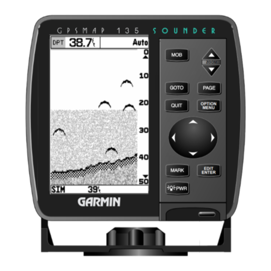
Each of these techniques is described in the reference section of the manual and/or on your GPSMAP 135 Sounder quick reference guide. To continue our tour, let’ s move on to the sounder page. - Page 17 Thermocline Whiteline The sounder page lets you use the GPSMAP 135 as a fishfinder. The top of the screen contains any of seven selectable data field options, while the middle of the page contains a right-to-left moving sonar image of the water beneath your boat.
- Page 18 B. The digital depth of the waypoint is captured with the underwater waypoint function. The GPSMAP 135 Sounder uses three range modes: auto, manual, and window. Auto mode displays the most information possible while continuously showing the bottom. Manual mode lets you select the displayed depth. Window mode allows you to define a starting depth and length of the range window.
- Page 19 The bottom half shows a portion of the original picture at 1/2 depth scale. • 2X Full Screen––Displays the 2X zoomed picture on the full GPSMAP 135 Sounder screen and does not show the original scale picture.
- Page 20 Let’ s continue the Getting Started Tour with the map page. 1. Press the J key. The GPSMAP 135 Sounder’ s map page combines digital chartplotting with a user-selectable display of navigation data and a built-in worldwide database to 64 nm.
-
Page 21: Using The Map Cursor
Now that you have a feel for how the cursor works, let’ s move on and see how the GPSMAP 135 Sounder works on the water. To help you practice using the map page and other features, we’ve stored a practice route in the receiver’ s perma- nent memory so you can see exactly what you’ll experience when you’re navigat-... -
Page 22: Going To A Destination
This will also give us an idea of how the O key is used throughout the GPSMAP 135 Sounder system to provide context-sensitive options and func- tions. Let’ s give it a try by activating the practice route stored in memory for navi- gation: 1. - Page 23 A data field at the top of the page will now display the bearing and distance to the second route waypoint. To get started, let’ s enter a speed for our vessel, which we can do from the ‘Setup Simulator?’ listing on the options page. The setup sim- ulator page is also available from any other page in the main page sequence.
- Page 24 GETTING STARTED Reviewing and Creating Waypoints on the Map A. Waypoints can be created from the map display by moving the cursor to the desired position and press- ing the EDIT/ENTER key. B. The create new waypoint page will automatically assign the next available three-digit number as the default waypoint name.
- Page 25 Whenever the GPSMAP 135 Sounder is in simulator mode, you can adjust your speed and course from the navigation page using the R keypad. As you head toward each waypoint in the tour route, try adjusting your boat speed and course to get a feel for how the highway works.
-
Page 26: Using The Navigation Page
GETTING STARTED Using the Navigation Page A. To reset the simulator to steer the desired course automatically, select the ‘Auto COG’ setting from the options page. B. The highway scale can be set to a 1/4-, 1/2-, 1-, 2-, or 4-nm/mi/km range with the ZOOM keys. To adjust the simulated boat speed: 1. -
Page 27: Active Route Page
As you’ve seen, the primary pages provide status, position, fishfinding, naviga- tion and map information. The tour’ s last page is the main menu page, which allows access to the GPSMAP 135 Sounder’ s waypoint, route and planning func- tions, as well as various operational and navigation setup features. - Page 28 Congratulations! You’ve now gone through the basic operation of the GARMIN GPSMAP 135 Sounder. Your new digital chartplotter is a powerful tool with many advanced features not covered in the Getting Started tour. For detailed instructions on using these features or performing a specific task, please refer to the quick ref- erence guide or the appropriate reference section of this manual.
-
Page 29: Getting Started
3 seconds, until the screen is blank. The next section of the manual describes the pages and functions of the GPSMAP 135 Sounder in detail. If you are unable to locate a specific option or function, please refer to the index on pages 96-98. -
Page 30: Section 1: Gpsmap Status Page
Dilution of Precision Status Bar The GPSMAP 135 Sounder status page provides a visual reference of various receiver functions, including current satellite coverage, receiver operating mode and current receiver accuracy. The status information will give you an idea of what the receiver is doing at any given moment. - Page 31 Receiver Status, EPE & DOP Receiver status is indicated at the top of the page, with the current estimated position error (EPE) and dilution of precision (DOP) to the left of the sky view. DOP is an indication of satellite geometry quality measured on a scale of one to ten (lowest numbers the best, highest numbers the poorest).
-
Page 32: Section 2: Position
(see page 16). Status Page Options The GPSMAP 135 Sounder’ s status page features a context-sensitive options page that provides access to functions and features relating to the status page. To display the status page options: 1. -
Page 33: Section 2: Position Page
Day Status Bar The GPSMAP 135 Sounder position page shows you where you are, what direc- tion you are heading and how fast you are going. The top of the page features a compass tape to indicate the direction you’re heading (while you’re moving), and four user selectable data fields: course over ground (COG), speed over ground (SOG), distance traveled (TRP) and altitude (ALT). -
Page 34: Section 3: Sounder
Position Page Options The GPSMAP 135 Sounder’ s position page features a context-sensitive options page that provides access to functions and features relating to the position page. To display the position page options: 1. -
Page 35: Section 3: Sounder Page
Whiteline Thermocline The sounder page is where your GPSMAP 135 Sounder becomes a powerful fishfinder. The top of the screen contains any of seven selectable data field options, while the middle of the page contains a right-to-left moving sonar image of the water beneath your boat. - Page 36 Range Modes The GPSMAP 135 Sounder uses three depth range modes: auto, manual, and window. Auto is the default and continually adjusts the screen display to show the maximum amount of data possible, while always showing the bottom; manu- al allows you to adjust the sonar display’...
- Page 37 The bottom half shows the original picture at 1/2 depth scale. • 2X Full Screen - Displays the 2X zoomed picture on the full GPSMAP 135 Sounder screen and does not show the original scale picture.
-
Page 38: Moving The Zoom Window
SECTION SOUNDER PAGE Zoom Window A. Auto zoom will show the most information pos- sible while continually showing the bottom on each half of the split screen. B. You can switch from manual to auto mode even while in the zoom mode, by pressing and hold- ing the arrow keypad up or down until you hear a triple beep, and then pressing it once more. - Page 39 Map/Sounder Page Split Screen The GPSMAP 135 Sounder can be configured to display a split screen display of a sounder window and map page simultaneously to let you see cartography and sounder information at the same time. The split screen is activated from the map page only.
- Page 40 SECTION SOUNDER PAGE Sounder Options A. Use the sounder options page to change the sounder page display to fit your needs. B. Three range modes may be selected. Sounder Page Options The sounder options page lets you customize the sounder to your needs. To display the sounder page options: 1.
- Page 41 • Setup Page Display?–– allows you to select the fields displayed in the data section of the sounder page. The following options are available: • 1 Field • 3 Fields & Compass • 1 Field & Compass • 3 Fields & CDI •...
-
Page 42: Sounder Setup
To access sounder setup: 1. Highlight the ‘Sounder Setup?’ option and press appear. determines how the GPSMAP 135 Sounder identifies and labels • Fish ID— sonar targets on the viewing screen. Three settings are available: • Off–is the default setting and shows all sonar target information as arches. - Page 43 2. Select from OFF, AUTO, or ON and press • Keel Offset - allows you to set the point from which the GPSMAP 135 Sounder will measure depth. This makes it possible to measure depth from the bottom of your keel instead of from the transducer's location.
-
Page 44: Section 3: Sounder
• Speed Calibration - If you are using a transducer equipped to display speed through water (STW), calibration is required to ensure that the STW displayed by your GPSMAP 135 Sounder will be accurate. The unit may be calibrated automatically or manually, but auto calibration is recommended and is the default setting. -
Page 45: Section 4: Map
To use Manual Calibration: 1. Ensure manual calibration mode is selected in the speed calibration field, if not, press , highlight ‘Manual Calibrate?’, and press 2. Press . The slider bar will turn black and the calibration range bar will turn to white. -
Page 46: Section 4: Map Page
Boat Icon Status The GPSMAP 135 Sounder’ s map page provides a comprehensive display of electronic cartography, plotting and navigational data. The map display shows your boat on a digital chart, complete with geographic names, navaids, depth con- tours and a host of other chart features. It also plots your track and displays any routes and waypoints you create. - Page 47 • If the boat icon attempts to go off the display, the zoom level may need to be adjusted to keep cartography on screen. Whenever the R keypad is pressed, the GPSMAP 135 Sounder will enter cur- sor mode. In cursor mode: •...
-
Page 48: Using The Cursor
SECTION MAP PAGE Using the Cursor A. To create a new waypoint at the cursor, move the cursor to the desired position and press EDIT/ENTER. B. The create new waypoint page will appear, where you may change the waypoint name, symbol and comment before saving the waypoint. - Page 49 1. Press the up key to zoom out and the down The GPSMAP 135 Sounder’ s system has a built-in worldwide database to 64 n.m.(see Appendix D for a built-in coverage map), with more detailed coverage available through the use of G-chart...
-
Page 50: Map Page Options
Map Page Options The GPSMAP 135 Sounder map page is designed to be a flexible tool that can be custom-tailored to your exact navigation needs. The map options page pro- vides access to many of the features and functions that will help you configure the map page to your own preferences. -
Page 51: Map Configuration
• Configure the Map?— allows you to determine what chart features are displayed on a particular map scale to prevent excessive clutter. The map configuration page features an on/off grid with a list of chart features down the left side. The zoom scales are displayed across the top of the grid with the chart scale currently in use also indicated. - Page 52 MAP PAGE SECTION Map Configuration & Map Colors A. To calibrate the map, highlight the ‘Calibrate the Map?’ option and press EDIT/ENTER. B. A satellite icon will remain on the map to indi- cate the GPS position, while the boat marker will reflect the calibration changes.
-
Page 53: Section 5: Navigation
• Setup Page Display?— allows you to specify the fields displayed in the data win- dow section of the map page by selecting one of the following display options: Note: The last two display options make it possible to display both the map page and sounder page simultaneously as a split screen. - Page 54 SECTION MAP PAGE Options • Change Data Fields?— allows you to specify the data displayed in each data field used on the map display. The following options are available: • BRG- bearing to active wpt • DIS- distance to active wpt •...
-
Page 55: Section 5: Navigation Page
GPSMAP 135 Sounder Navigation Page Compass Tape Graphic Highway Pointer to Waypoint Whenever a GOTO, MOB, TracBack or route has been activated, the GPSMAP 135 Sounder will provide digital and graphic steering guidance to the destination with the navigation page. The top half of the nav page features four user-selectable data fields that display the bearing (BRG) and distance (DIS) to waypoint, along with your current course (COG) and speed over ground (SOG). - Page 56 1. Press the up or down arrow of the key to select the desired setting. Navigation Page Options The GPSMAP 135 Sounder’ s navigation options page allows you to define the nav data fields and select what waypoints are displayed on screen. To display the navigation page options: 1.
- Page 57 The following options are available for the navigation page: • Change Data Fields?— allows you to define the data displayed in any of the six user-selectable data fields. Thirteen data options are available: • BRG • DIS • SOG • COG •...
-
Page 58: Section 7: Waypoints
The GPSMAP 135 Sounder’ s main menu page provides access to various way- point, system, navigation and interface management and setup menus. The main menu page is available from any page in the GPSMAP 135 Sounder’ s system, and is accessed through the O key. -
Page 59: Creating And Using Waypoints
Mark Key The GARMIN GPSMAP 135 Sounder’ s M key lets you quickly capture your present position— or cursor or navaid position— in order to create a new way- point. You must have a valid position fix to mark your present position. - Page 60 The mark key may also be used on the map page to mark the cursor position or an on-screen navaid. To mark a navaid, select the desired navaid with the cursor. The GPSMAP 135 Sounder will use the navaid text shown on the cartography as the default comment.
-
Page 61: Creating Waypoints Graphically
Creating Waypoints Graphically Waypoints may also be quickly created from the map display, which allows you to ‘point and shoot’ at any map position to create a new waypoint. To create a new waypoint graphically: 1. Use the keypad to move the cursor to the desired map position. If you want to create the new waypoint at an on-screen navaid, highlight the navaid on the map display. - Page 62 A new waypoint may also be created without knowing position coordinates by entering its range and bearing from an existing waypoint or your present position. The GPSMAP 135 Sounder will then calculate the position coordinates for you, using the reference selected.
- Page 63 Reviewing & Editing Waypoints Once you have created and stored a waypoint, it may be modified, reviewed, renamed or deleted at any time through the waypoint definition page. The way- point definition page is available for any stored waypoint by highlighting the desired waypoint from the map display or selecting it from waypoint or nearest waypoint lists and pressing the T key once.
- Page 64 WAYPOINTS SECTION Waypoint Definition Page Options A. To review or edit a waypoint on the map display, select the ‘Edit Wpt On Map?’ option. B. To move the selected waypoint, press EDIT/ENTER. Use the arrow keypad to select the new position, and press EDIT/ENTER to finish. Waypoint Definition Page Options The waypoint definition page also features an options page that allows you to edit the selected waypoint on the map display, rename the selected waypoint or...
-
Page 65: Nearest Waypoints
Waypoint Submenus The GPSMAP 135 Sounder’ s main menu page features four waypoint submenus that let you manage a large number of waypoints quickly and efficiently. The sub- menus also provide a continuously updated nearest waypoints list and a proximity waypoint alarm function that can be used to define an alarm circle around sub- merged hazards, shallow waters, etc. -
Page 66: Section 7: Waypoints
SECTION WAYPOINTS Proximity Waypoints A. Whenever you enter a proximity waypoint’s alarm circle, a ‘PRX’ indicator will appear in the status bar (the alarms option must be set to the ‘On’ position). Once you’ve left the alarm circle, the proximity indicator will automatically reset. B. -
Page 67: Create Waypoint
Create Waypoint The third waypoint submenu available from the main menu page is the ‘Create Waypoint’ submenu, which allows you to create a new waypoint by manually entering coordinates. Instructions for using the create waypoint submenu are pro- vided on page 36. Waypoint List The last waypoint category available from the main menu is the waypoints list, which displays a master list of all waypoints currently stored in memory. -
Page 68: Selecting A Goto Graphically
39. Going to a Destination The GPSMAP 135 Sounder provides four ways to navigate to a destination: GOTO, MOB, TracBack and route navigation. The easiest method for select- ing a destination is the GOTO function, which lets you select a destination way- point and quickly sets a direct course from your present position. - Page 69 GOTO Key Options The GOTO options page provides a list of additional GOTO options that let you start a TracBack route, select a destination waypoint from the nearest way- points list, select a route to navigate, or cancel the current GOTO destination. To display the GOTO options: 1.
- Page 70 2. Select the ‘Cancel GOTO’ option and press TracBack Navigation The third method of navigating to a destination is by using the GPSMAP 135 Sounder’ s TracBack feature. The TracBack function allows you to retrace your path using the track log automatically stored in the receiver’ s memory, which will eliminate the need to store waypoints along the way.
-
Page 71: Tracback Navigation
2. Highlight the ‘Start TracBack?’ option and press Once a TracBack has been activated, the GPSMAP 135 Sounder will take the track log currently stored in memory and divide it into segments called ‘legs’. Up to 30 temporary waypoints (e.g. T001) will be created to mark the most significant features of the track log in order to duplicate your exact path as closely as possi- ble. -
Page 72: Section 9: Routes
The last way to navigate to a destination is to create a user-defined route. The GARMIN GPSMAP 135 Sounder system lets you create and store up to 20 reversible routes (numbered 1-20), with up to 30 waypoints each. Routes can be created and modified right from the map page, allowing you to see each route graphically on-screen as you create, review, modify or navigate the route. - Page 73 Once a route has been created graphically (and the Q key has been pressed to finish), the map display will automatically enter the route review mode. The arrow pointer will be replaced by the map cursor, located at the last route waypoint. The route edit mode allows you to review and modify the route displayed through a pop-up window menu for each waypoint.
- Page 74 B. The ‘Edit As Text?’ option allows you to review and modify waypoints by text entry. The GPSMAP 135 Sounder’ s route edit mode also allows you to insert a new route waypoint in any route leg using the map cursor.
-
Page 75: Edit Options
To insert a new waypoint before the selected route waypoint: 1. Highlight the ‘Insert?’ option and press 2. Enter the name of the new waypoint using the the new waypoint from the nearest list, waypoint list, or map display. 3. Press to finish. - Page 76 Route List Page The GPSMAP 135 Sounder’ s route list page numerically lists all the routes cur- rently stored in memory, with the route number and comment displayed. Route 00 is always reserved for the TracBack route, while routes 1-20 serve as storage routes (route 20 is stored as the GPSMAP tour route, which may be deleted at any time).
- Page 77 Route List Page Options (cont.) • Clear Route?— allows you to clear all waypoints from the selected route. To clear the selected route: 1. Highlight the ‘Clear Route?’ option and press 2. Press to confirm the clear route warning. • Copy Route?— allows you to copy the waypoints of a selected route to another route.
- Page 78 EDIT/ENTER. Active Route Page Whenever you have activated a route in the GPSMAP 135 Sounder system, the active route page will appear in the main page sequence. The active route page shows each waypoint of the active route, with the waypoint name, desired track, cumulative distance and ETE or ETA for each waypoint from your present position.
- Page 79 Active Route Page Options The following options are available from the active route page: • Invert Route?— activates the active route in reverse order and begins navigation. • Activate Route?— reactivates the active route and selects the route leg closest to your current position as the new active leg.
-
Page 80: Section 10: Setup Menus
Track Log Submenu The GPSMAP 135 Sounder’ s main menu page’s track submenu lets you speci- fy whether or not to record a track plot (an electronic recording of your path) and define how it is recorded. It also provides an indicator of the track memory used and selects functions to clear the track memory and start a TracBack route. -
Page 81: Setup Menus
Trip and Fuel Planning The GPSMAP 135 Sounder’ s trip and fuel planning submenu lets you plan and review distance, fuel, and ETE/ETA information between any two waypoints; your present position and a stored waypoint; or any part of a stored route. Sunrise and sunset information is also provided. - Page 82 SECTION SETUP MENUS Route & Trip Planning A. To plan cumulative totals for an entire route, select the ‘All’ option from the leg field. B. To plan cumulative totals through a particular leg, select the ‘Hold First Waypoint?’ option from the Trip and Fuel Planning options page.
-
Page 83: Sunrise/Sunset Planning
The sounder only and GPS only modes allow you to determine what type of information the GPSMAP 135 Sounder will give you. GPS only mode is useful when using the unit for land navigation while enroute to the water. -
Page 84: Setup Options
• Display Contrast provides a slide bar to adjust the LCD screen contrast in order to compensate for changes in temperature or lighting conditions. • Backlight Timeout provides an automatic shutoff for the GPSMAP 135 Sounder’s screen backlighting. Six settings are available: No Timeout (the backlight will stay on until it is turned off), 15 seconds (default setting);... - Page 85 . Select the ‘User Mag Var’ SECTION SETUP MENUS Navigation Setup A. The GPSMAP 135 Sounder will also display posi- tion coordinates in eight grid formats. B. To enter a user magnetic variation, select the ‘User Mag Var’ option and enter a direction and...
-
Page 86: Navigation Setup
135 Sounder system. For a list of the available map datums, see Appendix D. The default setting is WGS 84. • Velocity Filter allows you to select the GPSMAP 135 Sounder’s response time to changes in track or ground speed. Three settings are available: automatic, on, or off. - Page 87 Timers & Alarms Setup The timer & alarms submenu is used to control various alarm/timer settings. • Timer sounds an alarm when an entered interval (up to 99:59:59) has expired, or provides a continuous running clock timer to 99:59:59. To use the countdown timer: 1.
-
Page 88: Section 10: Setup Menus
Data Transfer is a proprietary interface that allows you to exchange data such as way- points, routes and track logs between GPSMAP units or a GARMIN PC kit. No In/NMEA Out provides navigation information to a compatible NMEA device such as an autopilot or radar. - Page 89 Using NMEA & DGPS Interface Settings If you are using an NMEA interface format, the NMEA format must be specified in the NMEA format field that will automatically appear when an NMEA option is selected. The appropriate baud rate will be set automatically. To select a NMEA format: 1.
-
Page 90: Section 11: Using G-Chart Cartridges
3. Use your thumb to firmly push the cartridge into place (until the cartridge will not go any further into the unit). If your GPSMAP 135 Sounder is on, a confirmation tone will sound when the cartridge has been properly installed and accepted. - Page 91 When you leave the area covered by the main map of a cartridge, the GPSMAP 135 Sounder will default back to using the built-in 64 nm database if it is available at the current scale.
-
Page 92: Appendix C
3. Once the GPSMAP 135 Sounder unit has been installed, connect the cable to the anten- na connector on the back of the display unit. Make sure that you turn the antenna cable... - Page 93 2. Mark and drill the four mounting holes for the fastener you are using. 3. Fasten the bracket to the surface using the appropriate fastener. 4. Insert the GPSMAP 135 Sounder into the mounting bracket. The bracket is designed for a tight fit to provide additional support when swiveling the unit.
-
Page 94: Transducer Installation
To flush mount the GPSMAP 135 Sounder: 1. Cut a 4.15” W x 4.67” H (105.4 x 118.6mm) hole in panel. 2. Place GPSMAP 135 Sounder into hole from the front until its flange rests against the mounting surface. 3. From the back side of the panel, loosely attach the bracket so that the slot in the ratchet area points away from the mounting panel. - Page 95 In order to filter Radio Frequency Interference (RFI) radiation which would possibly interfere with items such as televisions, radios, or other depth sounders which are operating in close proximity to the GPSMAP 135 Sounder, two ferrite bead filter clamps are included for attachment to the unit’ s cables. The clamps attach to your transducer and power cables near the point at which they connect to the back of your GPSMAP 135 Sounder.
-
Page 96: Specifications
Specifications Connecting the Power/Data Cable The power/data cable connects the GPSMAP 135 Sounder to a 10-40 volt DC system and provides interface capabilities for connecting external devices, includ- ing an external alarm. The color code in the diagram below indicates the appro- priate harness connections. -
Page 97: Wiring & Specifications
Usage: 10 watts max. Specifications subject to change without notice. * With optional GARMIN GBR 21 Beacon Receiver Input. ** Subject to accuracy degradation to 100m 2DRMS under the U.S. DOD-imposed Selective Availability Program. Note: For transducer specifications, see the booklet included with your... - Page 98 SECTION APPENDIX Messages The GPSMAP 135 Sounder uses an on-screen message prompt to alert you to important informa- tion. Whenever a message appears, press the key to view the message. Alarm Clock—The alarm clock has sounded. Anchor Drag Alarm—You have drifted out of the specified distance range.
- Page 99 Wypt Already Exists—The waypoint name Route Memory is Full—You have attempted to you’ve entered already exists in memory. create more than 20 routes. Waypoint Memory is Full—You have used all 250 waypoints in the GPSMAP 135 Sounder sys- tem. SECTION APPENDIX Messages...
-
Page 100: Appendix D
SECTION APPENDIX Map Datums The GPSMAP 135 Sounder’s built-in worldwide database includes chart coverage down to 64 nm (120 km) for the areas outlined above. Note that the database is only valid to 68º15’ of latitude. The maximum cursor latitude is 85º05’, and the maxi- mum waypoint latitude is 89º24.543 north or south. - Page 101 Corrego Alegr Corrego Alegre- Brazil Kerguelen Islnd Djakarta Djakarta (Batavia)- Sumatra Kertau 1948 Island (Indonesia) L. C. 5 Astro Dos 1968 Dos 1968- Gizo Island Liberia 1964 (New Georgia Islands) Luzon Mindanao Easter Isld 67 Easter Island 1967 Luzon Philippine European 1950 European 1950- Austria, Belgium,...
- Page 102 SECTION APPENDIX Map Datums NAD27 Greenland North American 1927- Rome 1940 Greenland (Hayes RT 90 Peninsula) Santo (Dos) NAD27 Mexico N. American 1927- Mexico Sao Braz NAD27 San Salvadr North American 1927- San Salvador Island Sapper Hill ‘43 NAD83 North American 1983- Alaska, Canada, Central Schwarzeck America, CONUS, Mexico...
- Page 103 SECTION Almanac Data—The satellite constellation information (including location and health of satellites) APPENDIX that is transmitted to your receiver from every GPS satellite. Almanac data must be acquired before GPS navigation can begin. Glossary Bearing (BRG)—The compass direction from your position to a destination. Course Over Ground (COG)—Direction of movement relative to a ground position.
- Page 104 SECTION APPENDIX Thermocline— A layer of water separating warmer water above from cooler water below. Glossary Turn (TRN)— The difference and direction in degrees between the bearing to your destination and your course over ground. The TRN value is used to indicate what direction, and how many degrees, to turn to get back on course.
- Page 105 The chart below gives an approximate UTC time offset for the various longitudinal zones. Check with local charts for more detailed information. If you are in daylight savings time, add one hour to the offset. Longitudinal Zone W180.0º to W172.5º W172.5º...
- Page 106 SECTION APPENDIX Index Definitions Alarm Setup Desired Track (DTK) Anchor Drag Alarm Depth Contours Antenna Installation Depth Units Arrival Alarm Dilution of Precision (DOP) AutoLocate 1,21-22 DGPS Setup DGPS Status Backlight Level Beacon Receiver Setup 78-79 Entering Initial Position Bearing Estimated Position Error (EPE) Bearing/Distance Calculation Estimated Time of Arrival (ETA)
-
Page 107: Appendix G
Keypad Tone Packing List Keypad Usage viii Page Sequence Physical Specifications Local Time Offset Point-to-Point Planning Position Format Magnetic Variation 75-76 Position Mode Main Menu Position Page Man Overboard Function Velocity Filters Map Calibration Power Off Map Configuration 41-42 Power On Map Datum List 90-92 Proximity Alarm... - Page 108 SECTION APPENDIX Index Satellite Sky View Track Log Signal Strength Bars 2,20 Track Memory Simulator Mode Track Plot Resolution Simulator Tour 4-19 Track Recording Sounder Page 7-9,25-35 Trip Odometer Chart Speed Turn (TRN) Fish Id Keel Offset Map/Sounder Split Screen 29,43 Units of Measure Noise Rejection...
- Page 109 ® © 1997 GARMIN Corporation 1200 E. 151st Street, Olathe, KS 66062 USA GARMIN (Europe) LTD Unit 5, The Quadrangle, Abbey Park Industrial Estate, Romsey SO51 9AQ UK Part Number 190-00107-00 Rev. C Printed in Taiwan...
Need help?
Do you have a question about the Sounder GPSMAP 135 and is the answer not in the manual?
Questions and answers