Table of Contents
Advertisement
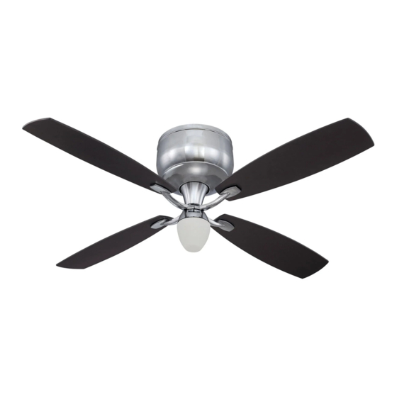
Installation Guide
For Model:
DE52CH4
E192641
net weight of fan: 20.94 lb (9.5 kg)
READ THESE INSTRUCTIONS AND
AND SAVE THEM FOR FUTURE USE
Table of Contents:
Safety Tips. pg. 1
Unpacking Your Fan. pg. 2
Parts Inventory. pg. 2
Installation Preparation. pg. 3
Fan Assembly. pg. 4
Wiring. pgs. 5 - 6
Activating Code. pgs. 6 - 7
Motor Housing Assembly. pg. 7
Blade Assembly. pg. 7
Wall Control Operation. pg. 10
Remote Control Operation. pg. 10
Testing Your Fan. pg. 10
Troubleshooting. pg. 11
Warranty. pg. 11
Parts Replacement. pg. 11
PRINTED IN CHINA
Advertisement
Table of Contents

Related Manuals for Craftmade DE52CH4


Summary of Contents for Craftmade DE52CH4
-
Page 1: Table Of Contents
READ THESE INSTRUCTIONS AND AND SAVE THEM FOR FUTURE USE Installation Guide For Model: DE52CH4 Table of Contents: Safety Tips. pg. 1 Unpacking Your Fan. pg. 2 Parts Inventory. pg. 2 Installation Preparation. pg. 3 Mounting Plate Installation. pgs. 3 - 4 Fan Assembly. -
Page 2: Safety Tips
SAFETY TIPS. WARNING: To reduce the risk of electrical shock, turn off the electricity to the fan at the main fuse box or circuit panel before you begin the fan installation or before servicing the fan or installing accessories. READ ALL INSTRUCTIONS AND SAFETY INFORMATION CAREFULLY BEFORE INSTALLING YOUR FAN AND SAVE THESE INSTRUCTIONS. -
Page 3: Unpacking Your Fan
1. Unpacking Your Fan. Carefully open the packaging. Remove items from Styrofoam inserts. Remove motor housing and place on carpet or Styrofoam to avoid damage to finish. Do not discard fan carton or Styrofoam inserts should this fan need to be returned for repairs. -
Page 4: Installation Preparation
3. Installation Preparation. blade edge To prevent personal injury and damage, ensure that the hanging location allows the blades a 7 feet inches (2.13m) (76cm) clearance of 7ft. (2.13m) from the floor and 30in. (76cm) from any wall or obstruction. This fan is suitable for room sizes up to 400 12ft. -
Page 5: Fan Assembly
4. Mounting Plate Installation. (cont.) Secure mounting plate to outlet box using original screws, spring washers and flat washers provided with new or original outlet box.* Pull electrical wiring from outlet box through center hole in the mounting plate. mounting plate *Note: It is very important that you use the proper hardware when installing the mounting plate as this will support the fan. - Page 6 ground (green or bare) 6. Wiring. white supply wire ground (green or bare) CAUTION: Be sure outlet box is properly grounded black supply wire and that a ground wire (GREEN or Bare) is present. Make sure all electrical connections comply with Local Codes or Ordinances and the National Electrical Code.
-
Page 7: Wiring. Pgs
6. Wiring. (cont). It is advisable to check that the wiring has been done correctly before proceeding. Connect WHITE wire from motor assembly to WHITE wire from light kit fitter. Connect receiver BLACK (or BLUE) wire from motor assembly to BLACK wire from light kit fitter. -
Page 8: Motor Housing Assembly
7. Automated Learing Process./ Activating Code. (cont.) IMPORTANT: Store the transmitter away from excess heat or humidity. To prevent damage to transmitter, remove the battery if transmitter will not used for long periods. Restore electrical power and then set slider switch on wall control to the ON position. -
Page 9: Blade Assembly
9. Blade Assembly. motor housing Time Saver: Washers for blade screw attachment can be set on each blade screw prior to installing blades. Locate 12 blade attachment screws and fiber blade attachment washers in one of the hardware packs. Hold screws and washers blade arm up to blade and align holes. - Page 10 10. Light Kit Assembly (Optional). (cont.) Remove 1 screw from post on underside of fitter plate and partially loosen the other 2 screws. Connect WHITE wire from motor assembly to WHITE wire from light kit fitter. Connect BLACK (or BLUE) wire from motor assembly to BLACK wire from light kit fitter.
-
Page 11: Wall Control Operation
11. Wall Control Operation. ON/OFF slider switch - turns wall control ON or OFF HI button - turns fan to HIGH speed MED button - turns fan to MEDIUM speed LOW button - turns fan to LOW speed FAN OFF button - turns fan OFF REV button - used to REVERSE blade direction (fan must be set on low before reversing blade direction) LIGHT button - (for use with optional light kit) turns light... -
Page 12: Troubleshooting
Return fan, shipping prepaid, to transmitter and wall control are set properly. Craftmade/Ellington. We will repair or ship you a 3. Verify that receiver is wired properly. replacement fan, and we will pay the return shipping cost.
Need help?
Do you have a question about the DE52CH4 and is the answer not in the manual?
Questions and answers