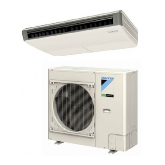
Daikin RZQ18PVJU (9) Installation Manual

Daikin RZQ18PVJU (9) Installation Manual

Split system air conditioners

Advertisement

SPLIT SYSTEM Air Conditioners
MODELS
RZQ18PVJU (9)
RZQ24PVJU (9)
RZQ30PVJU
RZR18PVJU
RZR24PVJU
RZR30PVJU
Read these instructions carefully before installation.
Keep this manual in a handy place for future reference.
This manual should be left with the equipment owner.
Lire soigneusement ces instructions avant l'installation.
Conserver ce manuel à portée de main pour référence ultérieure.
Ce manuel doit être donné au propriétaire de l'équipement.
Lea cuidadosamente estas instrucciones antes de instalar.
Guarde este manual en un lugar a mano para leer en caso de tener alguna duda.
Este manual debe permanecer con el propietario del equipo.

INSTALLATION MANUAL

English
Français
Español

Advertisement

Table of Contents
loading
Need help?

Need help?

Do you have a question about the RZQ18PVJU (9) and is the answer not in the manual?

Questions and answers

Summary of Contents for Daikin RZQ18PVJU (9)

  • Page 1: Installation Manual

    INSTALLATION MANUAL SPLIT SYSTEM Air Conditioners English MODELS RZQ18PVJU (9) RZQ24PVJU (9) Français RZQ30PVJU RZR18PVJU RZR24PVJU Español RZR30PVJU Read these instructions carefully before installation. Keep this manual in a handy place for future reference. This manual should be left with the equipment owner. Lire soigneusement ces instructions avant l’installation.
  • Page 2: Table Of Contents

    SPLIT SYSTEM Air Conditioners Installation manual CONTENTS DANGER 1. SAFETY CONSIDERATIONS ........... 1 • Refrigerant gas is heavier than air and replaces oxygen. 2. INTRODUCTION ............... 3 A massive leak can lead to oxygen depletion, especially in basements, and an asphyxiation hazard could occur 3.
  • Page 3 • Indoor units are for indoor installation only. Outdoor than those specifi ed by Daikin are used, fi re or explo- units can be installed either outdoors or indoors. sion may occur.
  • Page 4: Introduction

    • This air conditioner is an appliance that should not be Technical specifi cations accessible to the general public. (∗<a> and ∗<b> in the table indicate the operating condition • The wall thickness of fi eld-installed pipes should be (shown in the left fi gure).) selected in accordance with the relevant local, state, RZQ18PVJU RZQ24PVJU...
  • Page 5: Before Installation

    Main components • If strong wind whose velocity is 11 mph or more blows to the outdoor unit from the air outlet side, the air fl ow For main components and function of the main components, rate of the outdoor unit is reduced, the outlet air is refer to the Engineering Data Book.
  • Page 6 When two or more outdoor units are installed side Branch switch Branch switch and overcurrent and overcurrent by side protective device protective device • When an obstruction is present on the both sides Indoor unit Indoor remote controller (in.) • When an obstruction is present also in the upward area DANGER When one outdoor unit is installed individually...
  • Page 7 (B) When an obstruction is present on the air outlet side • When the upward area is open • When the upward area is open When one outdoor unit is installed individually When one outdoor unit is installed individually L>H When two or more outdoor units are installed side When two or more outdoor units are installed side by side...
  • Page 8 When only two outdoor units are installed side by • When an obstruction is present also in the upward area side When one outdoor unit is installed individually The dimensional relationship between H, L and A is as shown in the table below. The dimensional relationship between H, L and A is as shown in the table below.
  • Page 9: Cautions On Installation

    (D) When outdoor units are stacked When two or more outdoor units are installed side When an obstruction is present on the air outlet by side side The dimensional relationship between H, L and A is as NOTE shown in the table below. Only two outdoor units can be stacked.
  • Page 10: Refrigerant Piping Work

    REFRIGERANT PIPING WORK Location Working period Protection method 1 month or more Pinch pipes CAUTION Outdoor Less than 1 month Pinch or tape pipes <To piping technician> Indoor Regardless of period • Make sure to open the stop valves after fi nishing the piping work.
  • Page 11 Cautions on connecting the connection piping Tightening Flare dimension Pipe size Flare shape (in.) torque (ft·lbf) A (in.) • When it is expected that water condensed in the stop valve will reach the indoor unit through the gap between the heat R0.016 φ3/8”...
  • Page 12 • Vacuum drying - Use a vacuum pump which can evacuate • Charge the refrigerant to the liquid pipe in its liquid state. up to –14.6 psi or less. Since R410A is a mixed refrigerant, its composition changes [Procedure] Operate the vacuum pump for evacuation for if charged in a state of gas and normal system operation 2 hours or more using both liquid pipe and gas pipe until the would no longer be assured.
  • Page 13: Electric Wiring Work

    [Stop valve operation method] Stop valve operation Prepare hexagon wrenches (whose size is 4 mm and 6 mm). Cautions on handling the stop valve How to open the stop valve • The fi gure below shows the name of each part required in Insert a hexagon wrench into the valve stem, and turn the handling the stop valve.
  • Page 14 〈Precautions when knocking out knockout holes〉 • Perform the electric wiring work in accordance with the “electric wiring diagram label”. • To punch the knockout hole, hit it with a hammer. Make sure to turn OFF the branch switch and overcurrent •...
  • Page 15 CAUTION • After fi nishing the electric wiring work, confi rm that all the wirings are connected securely. Screw 〈〈Precautions when laying power wiring〉〉 (accessory) • Two electric wires of different thickness cannot be connected Lock nut Cover to the power terminal block. Cover (Handle) (Slack in the electric wires may generate abnormal heat.) Conduit...
  • Page 16: Checks After Completion Of Work

    Transmission wiring connection procedure Piping size and heat insulation: Refer to “6-1 Selection of piping material”, “6-5 Heat • If an excessive force is applied while connecting a cable insulation of piping”. to the terminal block on the PC board, the PC board may Check of stop valve: be damaged.
  • Page 17 • In the check operation, the status of the outdoor unit is <Cautions on check operation> checked, and incorrect wiring is checked for. • If the air conditioner is started within about 12 minutes after the power of the indoor/outdoor unit is turned on, the H2P (1) •...
  • Page 18: Caution For Refrigerant Leaks

    When a malfunction code is displayed in the remote When nothing is displayed in the remote controller controller • There might be a problem with the connection or transmis- (Check a malfunction code in the remote controller connected sion between the indoor unit and the remote controller. to the indoor unit.) Check connections, and check for wire breakage.
  • Page 19 Pay a special attention to the place, such as a basement, etc. where refrigerant can stay, since refrigerant is heavier than air. Procedure for checking maximum concentration Check the maximum concentration level in accordance with steps 1 to 4 below and take whatever action is necessary to comply.
  • Page 20 3P281953-2A EM08A096D (1102) HT...

Table of Contents