Honeywell T7351 Installation Instructions Manual
Commercial programmable thermostat for single- or multi-stage conventional/heat pump systems
Hide thumbs
Also See for T7351:
- Product data (21 pages) ,
- User manual (13 pages) ,
- Information (4 pages)
Table of Contents
Advertisement
Quick Links
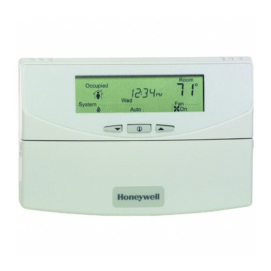
T7351 Commercial Programmable
Thermostat
FOR SINGLE- OR MULTI-STAGE CONVENTIONAL/HEAT PUMP
SYSTEMS
APPLICATION
The T7351 Commercial Programmable Thermostat
controls 24 Vac commercial single zone heating,
ventilating and air conditioning (HVAC) equipment. The
T7351 consists of a thermostat and subbase. The
thermostat includes the display and keypad for 7-day
programming. The subbase includes equipment control
connections. The subbase mounts on the wall and the
thermostat mounts to the subbase.
MERCURY NOTICE
If this control is replacing a control that contains
mercury in a sealed tube, do not place your old
control in the trash. Dispose of properly.
Contact your local waste management authority
for instructions regarding recycling and the
proper disposal of an old control. If you have
questions, call Honeywell Customer Care Center
at 1-800-468-1502.
INSTALLATION
When Installing this Product...
1. Read these instructions carefully. Failure to follow
them could damage the product or cause a hazard-
ous condition.
2. Check ratings given in instructions and on the
product to ensure the product is suitable for your
application.
3. Installer must be a trained, experienced service
technician.
4. After installation is complete, check out product
operation as provided in these instructions.
CAUTION
Electrical Shock or Equipment Damage
Hazard. Can shock individuals or short
equipment circuitry.
Disconnect power supply before installation.
INSTALLATION INSTRUCTIONS
Location
Do not install the thermostat where it can be affected by:
— drafts, or dead spots behind doors and in corners.
— hot or cold air from ducts.
— radiant heat from sun or appliances.
— concealed pipes and chimneys.
— unheated (uncooled) areas such as an outside wall
behind the thermostat.
IMPORTANT
To avoid electrical interference, which can
cause erratic performances, keep wiring runs as
short as possible and do not run thermostat
wires adjacent to the line voltage electrical dis-
tribution systems. Use shielded cable. The
cable shield must be grounded only at the con-
trolled equipment case.
Subbase
WHEN USED TO SENSE ROOM TEMPERATURE
Install the thermostat about 5 ft. (1.5m) above the floor in
an area with good air circulation at average temperature.
(See Fig. 1.)
WHEN NOT USED TO SENSE ROOM TEMPERATURE
When using the remote-mounted temperature (and
humidity) sensor(s) to sense ambient conditions, install
the thermostat in an area that is accessible for setting
and adjusting the temperature and settings.
Install the remote-mounted sensor(s) about 5 ft. (1.5m)
above the floor in an area with good air circulation at
average temperature (See Fig. 1).
If multiple remote sensors are required, they must be
arranged in a temperature averaging network consisting
of four sensors (See Fig. 2).
NOTE: Only T7770 models with no setpoint adjustment
can be used for temperature averaging.
62-0258
Advertisement
Table of Contents

Related Manuals for Honeywell T7351


Summary of Contents for Honeywell T7351
- Page 1 — radiant heat from sun or appliances. ventilating and air conditioning (HVAC) equipment. The — concealed pipes and chimneys. T7351 consists of a thermostat and subbase. The — unheated (uncooled) areas such as an outside wall thermostat includes the display and keypad for 7-day behind the thermostat.
-
Page 2: Mounting Subbase
M19606A Mounting Subbase Fig. 2. Four T7770A Sensors providing temperature The subbase mounts horizontally. averaging network for T7351 Thermostat. IMPORTANT • When using the internal temperature or humidity sensor, the device must be mounted horizontally (with the LCD facing upwards). Precise leveling is not needed. -
Page 3: System Settings
T7351 COMMERCIAL PROGRAMMABLE THERMOSTAT SETTINGS ENGAGE TABS AT TOP OF THERMOSTAT AND SUBBASE OR WALLPLATE. Using Thermostat Keys The thermostat keys are used to: • set current time and day, • program times and setpoints for heating and cooling, • override the program temperatures, •... -
Page 4: Installer Setup
75° F (24° C) 85° F (29° C) 78° F (26° C) press NOTE: Pressing Run/Copy again while in this Temporary Standby Set Schedule Room mode displays the T7351 firmware version Not Occupied12 StartTime number. MinsDays MonTueWedThuFri SatSunHol 3. To return to a Setup item, cycle through the options. - Page 5 T7351 COMMERCIAL PROGRAMMABLE THERMOSTAT Table 3. Installer Setup. Text Default Choices Notes DEGREES 0 0 -1 Degree Temperature Format 0: Degrees F 1: Degrees C CLOCK 0 - 1 Clock Display Format 0: 12 hour 1: 24 hour KEYLOCK 0...
- Page 6 T7351 COMMERCIAL PROGRAMMABLE THERMOSTAT Table 3. Installer Setup. (Continued) Text Default Choices Notes XFAN HT YES or NO Extended Fan on Heat NO: None YES: 90 seconds XFAN CL YES or NO Extended Fan on Cool NO: None YES: 40 seconds...
- Page 7 T7351 COMMERCIAL PROGRAMMABLE THERMOSTAT Table 3. Installer Setup. (Continued) Text Default Choices Notes MAXHTOA 40° F -20° - 120° F Maximum Heat Outdoor Air Temperature (Only Displayed if Outdoor Sensor is (4° C) (-29° - 49° C) Selected) MINCLRT 0 - 20 DDF/HR Minimum Cool Recovery Ramp Rate...
-
Page 8: Special Functions
T7351 COMMERCIAL PROGRAMMABLE THERMOSTAT Table 5. T7351 Key Function Summary. Grouping Button Definition Information Down Arrow Lowers setpoint, day, or time. When setting times or temperatures, hold key " down to continuously decrease value. Also can make temporary change in temperature setpoint. - Page 9 Get Factory Schedule (Info/Clear) Performing this operation reverts the schedules to the factory defaults: There are five methods through which the T7351 can 1. Press both Info and Clear Start Time. control for dehumidification. Three of them modify the 2. The display gives the option to revert to FAC SCH.
-
Page 10: Wiring Diagrams
T7351 COMMERCIAL PROGRAMMABLE THERMOSTAT Options Utilizing Auxiliary Output Dehumid Hot Gas BP The auxiliary output operates as shown in Table 6. There are two dehumidification options that utilize the auxiliary output. They are: Table 6. Hot Gas Bypass Dehumidification Logic. - Page 11 Bad thermostat location. Relocate the thermostat. Display shows three dashes and a T7351 is set for remote sensing and sensor is missing or circuit degree sign (all systems shut is either open or shorted. down). Temperature Upper or lower temperature limits...
- Page 12 T7351 COMMERCIAL PROGRAMMABLE THERMOSTAT Table 7. Troubleshooting Information. (Continued) Symptom Possible Cause Action Heat will not No power to the thermostat. Check that X terminal is connected to the system transformer. come on. Check for 24 Vac between X and RH terminals.
Need help?
Do you have a question about the T7351 and is the answer not in the manual?
Questions and answers