Honeywell T7350 Installation Instructions Manual
Commercial programmable thermostat
Hide thumbs
Also See for T7350:
- System engineering (44 pages) ,
- Product data (40 pages) ,
- User manual (40 pages)
Table of Contents
Advertisement
Quick Links
T7350 Commercial Programmable
Thermostat
FOR SINGLE- OR MULTI-STAGE CONVENTIONAL/
HEAT PUMP SYSTEMS
APPLICATION
The T7350 Commercial Programmable Thermostat
controls 24 Vac commercial single zone heating,
ventilating and air conditioning (HVAC) equipment. The
T7350 consists of a thermostat and subbase. The
thermostat includes the display and keypad for 7-day
programming. The subbase includes equipment control
connections. The subbase mounts on the wall and the
thermostat mounts to the subbase.
MERCURY NOTICE
If this control is replacing a control that contains
mercury in a sealed tube, do not place your old
control in the trash. Dispose of properly.
Contact your local waste management authority
for instructions regarding recycling and the
proper disposal of an old control. If you have
questions, call Honeywell Customer Care Center
at 1-800-468-1502.
INSTALLATION
When Installing this Product...
1. Read these instructions carefully. Failure to follow
them could damage the product or cause a
hazardous condition.
2. Check ratings given in instructions and on the
product to ensure the product is suitable for your
application.
3. Installer must be a trained, experienced service
technician.
4. After installation is complete, check out product
operation as provided in these instructions.
CAUTION
Electrical Shock or Equipment Damage
Hazard.
Can shock individuals or short equipment
circuitry.
Disconnect power supply before installation.
INSTALLATION INSTRUCTIONS
Location
Do not install the thermostat where it can be affected by:
— drafts or dead spots behind doors and in corners.
— hot or cold air from ducts.
— radiant heat from sun or appliances.
— concealed pipes and chimneys.
— unheated (uncooled) areas such as an outside wall
behind the thermostat.
IMPORTANT
To avoid electrical interference, which can
cause erratic performances, keep wiring runs as
short as possible and do not run thermostat
wires adjacent to the line voltage electrical
distribution systems. Use shielded cable. The
cable shield must be grounded only at the
controlled equipment case.
Subbase
WHEN USED TO SENSE ROOM TEMPERATURE
Install the thermostat about 5 ft. (1.5m) above the floor in
an area with good air circulation at average temperature.
(See Fig. 1.)
WHEN NOT USED TO SENSE ROOM TEMPERATURE
When using the remote-mounted temperature (and
humidity) sensor(s) to sense ambient conditions, install
the thermostat in an area that is accessible for setting
and adjusting the temperature and settings.
CAUTION
Equipment Damage Hazard.
Can damage the TIM connection beyond
repair.
Disconnect the TIM cable prior to opening or
closing the thermostat cover.
NOTE: Allow sufficient clearance below the thermostat
to plug in the TIM cable.
Install the remote-mounted sensor(s) about 5 ft. (1.5m)
above the floor in an area with good air circulation at
average temperature. (See Fig. 1.)
If multiple remote sensors are required, they must be
arranged in a temperature averaging network consisting
of four sensors. (See Fig. 2.)
Place Bar Code Here
62-0195-08
Advertisement
Table of Contents

Related Manuals for Honeywell T7350


Summary of Contents for Honeywell T7350
- Page 1 — radiant heat from sun or appliances. ventilating and air conditioning (HVAC) equipment. The — concealed pipes and chimneys. T7350 consists of a thermostat and subbase. The — unheated (uncooled) areas such as an outside wall thermostat includes the display and keypad for 7-day behind the thermostat.
-
Page 2: Mounting Subbase
M29184 Mounting Thermostat on Subbase (Fig. 4) Fig. 2. Four TR21 sensors providing temperature averaging network for T7350 Thermostat. With the subbase installed, mount the thermostat: 1. Engage top subbase tabs into the thermostat top. Mounting Subbase 2. Swing the thermostat down. -
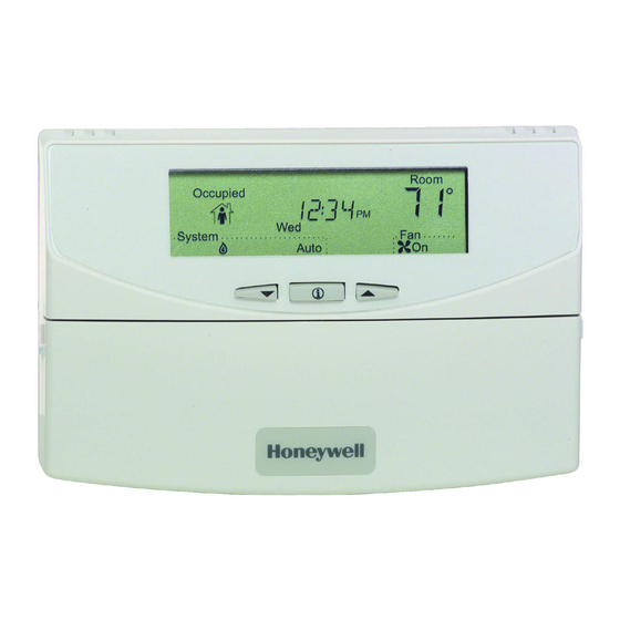
Page 3: Using Thermostat Keys
T7350 COMMERCIAL PROGRAMMABLE THERMOSTAT Setting System and Fan ENGAGE TABS AT TOP OF THERMOSTAT AND SUBBASE OR WALLPLATE. System default setting is Auto. Fan default setting is On. NOTE: Use System and Fan keys to change settings. System Settings — Auto: Thermostat automatically changes between heating and cooling based on indoor temperature. -
Page 4: Installer Setup
If you want to save the new configuration, use the up or down key to change NO to YES NOTE: The T7350 has serial communications to before pressing Run Schedule. facilitate use of an installer configuration tool. b. If you want the configuration to remain as it was... - Page 5 T7350 COMMERCIAL PROGRAMMABLE THERMOSTAT 5. Display prompts SAV CFG. If you want to save it, use the up or down key to change NO to YES before pressing Run Schedule again. Table 3. T7350 Key Function Summary. Grouping Button Definition Information Down Arrow Lowers setpoint, day, or time.
-
Page 6: Special Functions
Press both Run Schedule and Copy, then reconfigure display. the display. Bad thermostat location. Relocate the thermostat. Display shows three dashes and a degree T7350 is set for remote sensing and sensor is missing sign (all systems shut down). or circuit is either open or shorted. 62-0195—08... - Page 7 T7350 COMMERCIAL PROGRAMMABLE THERMOSTAT Table 4. Troubleshooting Information. (Continued) Symptom Possible Cause Action Temperature Upper or lower temperature limits were Check the temperature setpoints: settings will not reached. • Heating limits are 40 to 90°F (7 to 31°C) change. • Cooling limits are 45 to 99°F (9 to 37°C)
- Page 8 T7350 COMMERCIAL PROGRAMMABLE THERMOSTAT WIRING DIAGRAMS (FIG. 7-14) SUBBASE HEAT RELAY RELAY 1 COMPRESSOR HEAT CONTACTOR 1 RELAY 2 (HOT) (HOT) HEATING COOLING TRANSFORMER TRANSFORMER POWER SUPPLY. PROVIDE DISCONNECT MEANS AND OVERLOAD PROTECTION AS REQUIRED. WHEN INSTALLED ON A SYSTEM WITH TWO TRANSFORMERS, REMOVE THE FACTORY-INSTALLED JUMPER.
- Page 9 T7350 COMMERCIAL PROGRAMMABLE THERMOSTAT TR23 REMOTE SENSOR OUTDOOR HEAT SENSOR RELAY 2 10 11 12 DISCHARGE COMPRESSOR SENSOR CONTACTOR 2 SUBBASE HEAT RELAY RELAY 1 COMPRESSOR HEAT CONTACTOR 1 RELAY 3 (HOT) (HOT) HEATING COOLING TRANSFORMER TRANSFORMER POWER SUPPLY. PROVIDE DISCONNECT MEANS AND OVERLOAD PROTECTION AS REQUIRED.
- Page 10 T7350 COMMERCIAL PROGRAMMABLE THERMOSTAT TR23-H REMOTE SENSOR OUTDOOR HEAT SENSOR RELAY 2 10 11 12 DISCHARGE COMPRESSOR COMPRESSOR CONTACTOR 4 CONTACTOR 2 SENSOR SUBBASE W3/Y4 Y3 COMPRESSOR CONTACTOR 3 HEAT HUMIDITY MOTION RELAY RELAY 1 SENSOR SENSOR COMPRESSOR CONTACTOR 1...
- Page 11 T7350 COMMERCIAL PROGRAMMABLE THERMOSTAT TR23-H REMOTE SENSOR MODULATING OUTDOOR COOL – (4-20 mA) SENSOR MODULATING 10 11 12 DISCHARGE HEAT – (4-20 mA) SENSOR SUBBASE LONWORKS ® HEAT HUMIDITY MOTION RELAY RELAY 1 SENSOR SENSOR LONWORKS ® COMPRESSOR CONTACTOR 1...
- Page 12 T7350 COMMERCIAL PROGRAMMABLE THERMOSTAT DEHUMIDIFICATION (T7350D,H,M) There are five methods through which the T7350 can Reset Temp SetPt control for dehumidification. Three of them modify the The room temperature setpoint resets to a specified control algorithm, thus providing limited dehumidification number of degrees below the actual setpoint when room through cooling.
Need help?
Do you have a question about the T7350 and is the answer not in the manual?
Questions and answers