Table of Contents
Advertisement
Copyright and Warranty Notice
The information in this document is subject to change without notice and does not
represent a commitment on part of the vendor, who assumes no liability or
responsibility for any errors that may appear in this manual.
No warranty or representation, either expressed or implied, is made with respect to
the quality, accuracy or fitness for any particular part of this document. In no event
shall the manufacturer be liable for direct, indirect, special, incidental or
consequential damages arising from any defect or error in this manual or product.
Product names appearing in this manual are for identification purpose only and
trademarks and product names or brand names appearing in this document are
property of their respective owners.
This document contains materials protected under International Copyright Laws. All
rights reserved. No part of this manual may be reproduced, transmitted or
transcribed without the expressed written permission of the manufacturer and
authors of this manual.
If you do not properly set the motherboard settings causing the motherboard to
malfunction or fail, we cannot guarantee any responsibility.
Advertisement
Table of Contents

Related Manuals for Abit BE6-II


Summary of Contents for Abit BE6-II
- Page 1 Copyright and Warranty Notice The information in this document is subject to change without notice and does not represent a commitment on part of the vendor, who assumes no liability or responsibility for any errors that may appear in this manual. No warranty or representation, either expressed or implied, is made with respect to the quality, accuracy or fitness for any particular part of this document.
-
Page 3: Table Of Contents
BE6-II Motherboard User’s Manual Table of Contents CHAPTER 1. INTRODUCTION OF BE6-II FEATURES 1-1. F EATURES OF OTHERBOARD 1-2. S PECIFICATIONS 1-3. L AYOUT IAGRAM 1-4. T YSTEM LOCK IAGRAM CHAPTER 2. INSTALLING THE MOTHERBOARD 2-1. I NSTALLING THE OTHERBOARD TO THE HASSIS 2-2. - Page 4 APPENDIX A BIOS FLASHING USER INSTRUCTIONS APPENDIX B INSTALLING HIGHPOINT XSTORE UTILITY APPENDIX C HARDWARE MONITORING FUNCTION (INSTALLING THE WINBOND HARDWARE DOCTOR UTILITY) APPENDIX D INSTALLING THE DRIVER FOR ULTRA ATA/66 APPENDIX E THE THERMAL CABLE APPENDIX F BX 133 OVERCLOCKING GUIDE APPENDIX G HOW TO GET TECHNICAL SUPPORT APPENDIX H TROUBLESHOOTING (NEED ASSISTANCE?)
-
Page 5: Features Of This Motherboard
The BE6-II has the HPT366 Ultra ATA/66 Chipset built-in. This means, the BE6-II will support Ultra ATA/66 IDE devices. Ultra ATA/66 is the new standard for IDE devices. It enhances existing Ultra ATA/33 technology by increasing both performance and data integrity. -
Page 6: Specifications
! Three 168-pin DIMM sockets support SDRAM modules ! Supports up to 768MB MAX. (8, 16, 32, 64, 128, 256 MB SDRAM) ! Supports ECC 4. System BIOS ! CPU SOFT MENU ™ III, can easily set the processor parameters ! AWARD 6.0 Version BIOS BE6-II... - Page 7 Introduction of BE6-II Features ! Supports Plug-and-Play (PnP) ! Supports Advanced Configuration Power Interface (ACPI) ! Supports Desktop Management Interface (DMI) ! Year 2000 compliant 5. Multi I/O Functions ! 2x Channels of Bus Master IDE Ports supporting up to four Ultra DMA 33/66 devices...
- Page 8 States and certain other countries. Sound Blaster - LINK and SB-LINK trademarks of Creative Technology Ltd. # Specifications and information contained in this manual are subject to change without notice. Note All brand names and trademarks are the property of their respective owners. BE6-II...
-
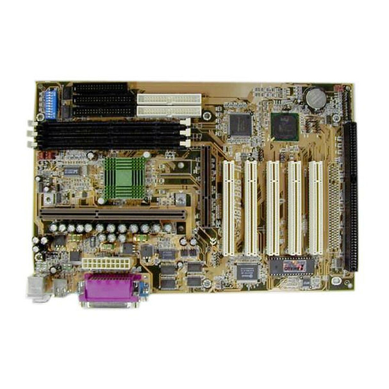
Page 9: Layout Diagram
Introduction of BE6-II Features 1-3. Layout Diagram Figure 1-2. Motherboard component location User’s Manual... -
Page 10: The System Block Diagram
Chapter1 1-4. The System Block Diagram Figure 1-3. System diagram of the 440BX chipset BE6-II... - Page 11 Installing the Motherboard Chapter 2. Installing the Motherboard This BE6-II motherboard not only provides all standard equipment for classic personal computers, but also provides great flexibility for meeting future upgrade demands. This chapter will introduce step by step all the standard equipment and will also present, as completely as possible, future upgrade capabilities.
-
Page 12: M Otherboard To The C Hassis
After the motherboard has been positioned, check to make sure everything is OK before putting the casing back on. Figure 2-2 shows you the way to affix the motherboard using studs or spacers: BE6-II... -
Page 13: Installing System Memory
PPGA processor, you have to use an additional adapter that allows you to use a Celeron PPGA processor in a slot 1 board. For this ABIT makes the SlotKET adapter. Note: ! Installing a heat sink and cooling fan is necessary for proper heat dissipation from your CPU. - Page 14 Step 2. Remove the computer’s chassis cover. Step 3. Before touching any electronic components, make sure you first touch an unpainted, grounded metal object to discharge any static electricity stored on your clothing or body. Figure 2-4. Memory module installation BE6-II...
- Page 15 Installing the Motherboard Step 4. Locate your computer’s 168-pin memory expansion DIMM socket. Step 5. Insert the DIMM module into the expansion socket as shown in the illustration. Note how the module is keyed to the socket. You can refer to figure 2-4 for the details.
-
Page 16: H Eaders And S Witches
If your system doesn't have such add-on cards or switches you can ignore some special feature connectors. Figure 2-5. All Connectors and Headers for the BE6-II First, Let’s see the headers that BE6-II uses, and what their functions are. BE6-II... - Page 17 Installing the Motherboard ATX: ATX Power Input Connector Caution If the power supply connectors are not properly attached to the ATX power supply, the power supply or add-on cards may be damaged. Attach the connector from the power supply to the ATX connector here. Remember you have to push the connector from the ATX power supply firmly to the end with the ATX connector, insuring that you have a...
- Page 18 This feature lets you wake up your computer via remote control through the modem. Note: Watch the pin position and the orientation BE6-II...
- Page 19 Installing the Motherboard WOL: Wake on LAN Header If you have a Network adapter that supports this feature, then you can connect the specific cable from the network adapter to this header. This feature lets you wake up your computer via remote control through a local area network.
- Page 20 ZIP device after you shutdown your computer. Otherwise, the onboard battery will run down. CCMOS: CMOS Discharge Jumper Jumper CCMOS discharge CMOS memory. When you install the motherboard, make sure this jumper is set for normal operation (pin 1 and 2 shorted). See figure 2-6. BE6-II...
- Page 21 Installing the Motherboard 2-11 Normal Operation (Default) Discharge CMOS Figure 2-6. CCMOS jumper setting Note Before you clear the CMOS, you have to turn the power off first (including the +5V standby power). Otherwise, your system may work abnormally or malfunction. PN1 and PN2 Headers PN1 and PN2 are for switches and indicators for the chassis’s front panel, there are...
- Page 22 BIOS setup, this function will not work. PN2 (Pin 1-2): Hardware Reset Switch Header Attach the cable from the case’s front panel Reset switch to this header. Press and hold the reset button for at least one second to reset the system. BE6-II...
- Page 23 PIN 9 Power On/Off signal PIN 9 +5VDC PIN 10 +3V Standby PIN 10 Suspend LED active PIN 11 Suspend signal PIN 11 No connection Let’s now see the I/O connectors that BE6-II uses, and what their functions are. User’s Manual...
- Page 24 “Primary” refers to the first connector on the motherboard, that is, the IDE1 connector on the motherboard. “Secondary” refers to the second connector on the motherboard, that is, the IDE2 connector on the motherboard. Two hard disks can be connected to each connector: The first HDD is referred to as the “Master”, BE6-II...
- Page 25 1 to the IDE1 (or IDE2) connector pin 1, then insert the wire connector into the IDE1(or IDE 2) connector. IDE3 and IDE4: ATA/66 Connectors The BE6-II supports the Ultra ATA/66 (Also known as Ultra DMA/66) specification. It enhances existing Ultra ATA/33 technology by increasing both performance and data integrity.
- Page 26 *The cable must be 80-conductor; the length should not exceed 18 inches. If all the above requirements are met, you can enjoy the Ultra ATA/66 features of your computer system. Figure 2-9. Photo of an Ultra ATA/66 Conductor Cable BE6-II...
- Page 27 Please refer figure 2-10. Figure 2-11. BE6-II back panel connectors Figure 2-11 shows the BE6-II back panel connectors, these connectors are for connection to outside devices to the motherboard. We will describe which devices will attach to these connectors below.
- Page 28 Parallel Port Connector This parallel port is also called an “LPT” port, because it usually connects to the printer. You can connect other devices that support this communication protocol, like a scanner, M.O. drive, etc. BE6-II...
-
Page 29: S Ettings
2-19 2-5. CPU Frequency Settings The BE6-II provides two ways to configure CPU settings. One uses the ABIT CPU Soft Menu III technology, the other uses DIP Switches. You can use the DS10 to enable or disable Soft Menu III. - Page 30 The DS10 lets you enable or disable Soft Menu III. The Soft Menu III allows you to configure the CPU settings easily through BIOS setup (refer to section 3-1). When you enable Soft Menu III, all DIP switches must be set to OFF. DS10 Disable Soft Menu III Enable Soft Menu III BE6-II...
- Page 31 Introduction of the BIOS Chapter 3. Introduction of the BIOS The BIOS is a program located on a Flash Memory chip on the motherboard. This program will not be lost when you turn the computer off. This program is also referred to as the “boot”...
- Page 32 ! Press F10 when you have completed setting up the BIOS parameters to save them and exit the BIOS Setup menu. ! Press Esc to Exit the BIOS Setup. ! Press F1 to display the General Help screen. In addition to the Item Help window, more information can be provided for the alternate BE6-II...
- Page 33 Introduction of the BIOS function by pressing the F1 key in any menu in the BIOS. ! Press F5 to reset current screen settings to their Setup Default values. ! Press F6 to return to the Fail-Safe Default setting i.e. if you use the wrong settings causing a system boot failure, use this function key to quickly return to the system default settings.
- Page 34 In this field, the CPU speed is indicated like this: CPU speed = External clock * Multiplier factor, select the CPU speed according the type and the speed of your CPU. For Intel Pentium II and Celeron ™ PPGA MMX processors, you can choose the following settings: BE6-II...
- Page 35 Introduction of the BIOS 233 (66) 266 (66) 300 (66) 333 (66) 300 (100) 350 (100) 400(100) 450 (100) 366 (66) 400 (66) 433 (66) 466 (66) 500 (66) 533 (66) 533 (133) 500 (100) 550 (100) 600(100) 600 (133) 650 (100) 667 (133) 700 (100)
- Page 36 CPU damage. I/O Voltage This item lets you select the voltage supplied to the DRAM, chipset and AGP. You can change values in the “I/O Voltage” option lists by using the arrow up and down keys. BE6-II...
- Page 37 Introduction of the BIOS !!! Warning !!! Using a higher voltage may result in the shortening of your computer components’ life. We strongly suggest you leave this item on default setting. In-Order Queue Depth Two options are available: 1 and 8. This item lets you set cache buffer for CPU data processing.
- Page 38 III again to set up the parameters all over again. Spread Spectrum Modulated For EMC (Electro-Magnetic Compatibility Test) testing you maybe need to adjust this item for optimal results, we do not recommend you change the default, except for special reasons. BE6-II...
-
Page 39: Standard Cmos Features Setup Menu
Introduction of the BIOS 3-2. Standard CMOS Features Setup Menu This contains the basic configuration parameters of the BIOS. These parameters include date, hour, VGA card, FDD and HDD settings. Figure 3-3. Standard CMOS Setup Screen Shot Date (mm:dd:yy): You can set the date in this item: month (mm), date (dd) and year (yy). Time (hh:mm:ss): You can set the time in this item: hour (hh), minute (mm) and second (ss). - Page 40 HDD manufacture to get the settings right. Access Mode: Since old operating systems were only able to support HDDs with capacities no bigger than 528MB, any hard disk with more than 528MB was unusable. AWARD BIOS features a BE6-II...
- Page 41 Introduction of the BIOS 3-11 solution to this problem: you can, according to your operating system, choose four operating modes: NORMAL - LBA - LARGE -Auto. The HDD auto detection option in the sub-menu will automatically detect the parameters of your hard disk and the mode supported.
- Page 42 3 Mode floppy drive. Video: You can select the VGA modes for your video adapter, four options are available: EGA/VGA - CGA 40 - CGA 80 - MONO. The default setting is EGA/VGA. BE6-II...
- Page 43 Introduction of the BIOS 3-13 Halt On: You can select which type of error will cause the system to halt. Five options are available: All Errors - No Errors - All, But Keyboard - All, But Diskette - All, But Disk/Key. You can see your system memory list in the lower right box, it shows the Base Memory, Extended Memory and total Memory size configurations in your system.
-
Page 44: Advanced Bios Features Setup Menu
If the Quick Power on Self-Test feature is enable, the BIOS will simplify the test procedures in order to speed up the boot process. The default setting is Enabled. BE6-II... - Page 45 Introduction of the BIOS 3-15 Virus Warning: This item can be set to Enabled or Disabled, the default setting being Disabled. When this feature is enabled, if there is any attempt from a software or an application to access the boot sector or the partition table, the BIOS will warn you that a boot virus is attempting to access the hard disk.
- Page 46 Off: At boot up, the Numeric Keypad is in cursor control mode. Typematic Rate Setting: This item allows you to adjust the keystroke repeat rate. When set to Enabled, you can set the two keyboard typematic controls that follow (Typematic Rate and Typematic Rate BE6-II...
- Page 47 Introduction of the BIOS 3-17 Delay). If this item is set to Disabled, the BIOS will use the default setting. The default setting is Enabled. Typematic Rate (Chars/Sec): When you press a key continuously, the keyboard will repeat the keystroke according to the rate you have set (Unit: characters/second).
- Page 48 Delay IDE Initial (sec): This item is used to support some old models or special types of hard disks or CD-ROMs. They may need a longer amount of time to initialize and prepare for activation. Since the BE6-II...
- Page 49 Introduction of the BIOS 3-19 BIOS may not detect those kinds of devices during system booting. You can adjust the value to fit such devices. Larger values will give more delay time to the device. The minimum number you can enter is 0, the maximum number you can enter is 15. The default setting is User’s Manual...
-
Page 50: Advanced Chipset Features Setup Menu
CAS and RAS strobe signals, used when DRAM is written to, read from, or refreshed. Fast gives faster performance; and Slow gives more stable performance. This item applies only when synchronous DRAM is installed in the system. BE6-II... - Page 51 Introduction of the BIOS 3-21 SDRAM RAS Precharge Time: Two options are available: 2 and 3. The precharge time is the number of cycles it takes for the RAS to accumulate its charge before DRAM refreshs. If insufficient time is allowed, refresh maybe incomplete and the DRAM may fail to retain data.
- Page 52 This function is used to meet the latency of PCI cycles to or from the ISA bus. This option must be enabled to provide PCI 2.1 compliance. If you have an ISA card compatibility problem, you can try to enable or disable this option for optimal results. BE6-II...
- Page 53 Introduction of the BIOS 3-23 AGP Aperture Size (MB): Seven options are available: 4 - 8 - 16 - 32 - 64 - 128 - 256 - Back to 4. This option specifies the amount of system memory that can be used by the AGP device. The aperture is a portion of the PCI memory address range dedicated for graphics memory address space.
-
Page 54: Integrated Peripherals
Back to Auto. The four IDE PIO (Programmed Input/Output) items let you set a PIO mode (0-4) for each of the four IDE devices that the onboard IDE interface supports. Modes 0 through 4 provide successively increased performance. In Auto mode (default setting), the system automatically determines the best mode for each device. BE6-II... - Page 55 Introduction of the BIOS 3-25 Master/Slave Drive Ultra DMA: Two options are available: Auto and Disabled. The default setting is Auto. Ultra DMA is a DMA data transfer protocol that utilizes ATA commands and the ATA bus to allow DMA commands to transfer data at a maximum burst rate of 33 MB/sec.
- Page 56 You may try to change the keyboard clock settings for optimal result. Onboard FDD Controller: Two options are available: Enabled and Disabled. The default setting is Enabled. You can enable or disable the onboard FDC controller. BE6-II...
- Page 57 Introduction of the BIOS 3-27 Onboard Serial Port 1: This is used to specify the I/O address and IRQ of Serial Port 1. Six options are available: Disabled - 3F8/IRQ4 - 2F8/IRQ3 - 3E8/IRQ4 - 2E8/IRQ3 - AUTO. The default setting is 3F8/IRQ4.
- Page 58 This setting lets you set the system action after a power failure. Three options are available: Off - On - Former-Sts. The default setting is Off. NOTE This function has to cooperate with the JP2 setting (see section 2-4). BE6-II...
-
Page 59: Power Management Setup Menu
Introduction of the BIOS 3-29 3-6. Power Management Setup Menu The difference between Green PCs and traditional computers is that Green PCs have a power management feature. With this feature, when the computer is powered on but inactive, the power consumption is reduced in order to save energy. When the computer operates normally, it is in Normal mode. - Page 60 ACPI is configured with an ACPI-aware operating system. Note If you enable the ACPI function in the BIOS setup, the SMI switch function will not work. BE6-II...
- Page 61 Introduction of the BIOS 3-31 System States and Power States Under ACPI, the operating system directs all system and device power state transitions. The operating system puts devices in and out of low-power states based on user preferences and knowledge of how devices are being used by applications. Devices that are not being used can be turned off.
- Page 62 Suspend Mode = 1 Min HDD Power Down = 1 Min PM Control by APM: Power Management is completely controlled by the APM. APM stands for Advanced Power Management, it is a power management standard set by Microsoft, Intel and other major manufacturers. BE6-II...
- Page 63 Introduction of the BIOS 3-33 Video Off Method: Three video off methods are available: "Blank Screen", "V/H SYNC + Blank" and "DPMS". The default is " V/H SYNC + Blank ". If this setting does not shut off the screen, select “Blank Screen”. If your monitor and video card support DMPS standard, select “DPMS”.
- Page 64 "hung". Power On by Ring: Two options are available: Enabled and Disabled. Default setting is Disabled. If you connect an external modem to the onboard serial port, the system will be turned on when a telephone ring-up occurs. BE6-II...
- Page 65 Introduction of the BIOS 3-35 Resume by Alarm: Two options are available: Enabled and Disabled. Default setting is Disabled. The RTC alarm can turn on the system. You can set Date (of month) and Time (hour, minute, and second) when you set this item to Enabled. Resume by LAN: Two options are available: Enabled and Disabled.
- Page 66 Mouse Break Suspend: Four options are available: Yes-No (COM1) -No (COM2) -No (PS/2) -Back to Yes. CPU FAN Off In Suspend Two options are available: Enabled and Disabled. When select Enabled the CPU fan turns off during Suspend mode BE6-II...
- Page 67 Introduction of the BIOS 3-37 3-7. PnP/PCI Configurations This section describes configuring the PCI bus system. PCI, or Personal Computer Interconnect, is a system which allows I/O devices to operate at speeds nearing the speed the CPU itself uses when communicating with its own special components. This section covers some very technical items and it is strongly recommended that only experienced users should make any changes to the default settings.
- Page 68 IRQ and DMA are assigned to PCI/ISA PnP or legacy ISA cards. IRQ Resources When resources are controlled manually, assign each system interrupt a type, depending on the type of device using the interrupt. Figure 3-10. PnP/PCI Configurations - IRQ Resources Setup Screen Shot BE6-II...
- Page 69 Introduction of the BIOS 3-39 , DMA Resources When resources are controlled manually, assign each system DMA channel a type, depending on the type of device using the DMA channel. Figure 3-11. PnP/PCI Configurations - DMA Resources Setup Screen Shot , Memory Resources This sub menu can let you control the memory resource.
- Page 70 NT, then you can specify the IRQ for the device installed on the new computer to fit the original computer settings. Note If you specify the IRQ in this item, then you cannot specify the same IRQ to the ISA bus, otherwise, it will cause a hardware conflict. BE6-II...
- Page 71 Introduction of the BIOS 3-41 This feature is for the operating system which will record and fix the PCI configuration status, if you want to change it. For the relations between the hardware layout of PIRQ (the signals from the PIIX4 chipset), INT# (means PCI slot IRQ signals) and devices, please refer to the table below: Signals PCI slot 1...
-
Page 72: Pc Health Status
These items list the current states of the CPU and environment temperatures as well as fan speeds (CPU fan and chassis fan). It can not be changed by the user. The following items list the voltage states of the system power. It is also unchangeable. BE6-II... -
Page 73: D Efaults
Introduction of the BIOS 3-43 3-9. Load Fail-Safe Defaults Figure 3-14. Load Fail-Safe Defaults Screen Shot When you press <Enter> on this item you get a confirmation dialog box with a message similar to: Load Fail-Safe Defaults (Y/N) ? N Pressing ‘Y’... -
Page 74: Set Password
Notice Do not forget your password. If you forget it, you will have to open the computer case, clear the contents of the CMOS, and boot the system up again. By doing this, you must reset all your parameters. BE6-II... -
Page 75: Save & Exit Setup
Introduction of the BIOS 3-45 3-12. Save & Exit Setup Figure 3-16. Save & Exit Setup Screen Shot Pressing <Enter> on this item asks for confirmation: Save to CMOS and EXIT (Y/N)? Y Pressing “Y” stores the selections made in the menus in CMOS - a special section of memory that stays on after you turn your system off. -
Page 76: Exit Without Saving
Pressing <Enter> on this item asks for confirmation: Quit without saving (Y/N)? Y This allows you to exit Setup without storing in CMOS any change. The previous selections remain in effect. This exits the Setup utility and restarts your computer. BE6-II... - Page 77 BIOS Flashing User Instructions Appendix A BIOS Flashing User Instructions When your motherboard needs to be upgraded with new features or some compatibility problems in the BIOS need to be fixed, you will need to use this BIOS flash utility. This utility is provided by Award Software makes it easy to flash by yourself.
- Page 78 Figure F-3 shows you what commands you can use for the flashing program. You need to go into the pure DOS environment and type awdflash. Figure F-3 will then appear. Figure F-3. Award Flash Memory Writer V7.22 Flash Commands Screen BE6-II...
- Page 79 “NEWBIOS” indicates the file name for the new BIOS which can be downloaded from our web site at http://www.abit.com.tw (the user can choose a different file name in place of NEWBIOS). “SAVEBIOS” indicates the filename of the old system BIOS (the user can choose a different file name in place of SAVEBIOS).
- Page 80 (3) The NEWBIOS file which can be download from ABIT web site. (4) AUTOEXEC.BAT, which has the following content: A:\AWDFLASH NEWBIOS /PY /SN /CC /CD For example, to update the BE6-II BIOS version to MJ (BE6-II_MJ.BIN), you need to type: A:\AWDFLASH BE6-II_MJ.BIN /PY /SN /CC /CD /CKS 3.
- Page 81 Install HighPoint XStore Pro Utility Appendix B Installing the HighPoint XStore Pro Utility We provide a useful and powerful utility in our product package, HighPoint XStore Pro. What does XStore do? The XStore Pro is a hard disk enhancement utility which can improve system performance.
- Page 82 For more detailed information, please check the read me file stored in the XStore Pro Program Group. If you want to upgrade to a new version of driver or want to know more about XStore Pro products, please go to the HighPoint Technologies Inc’s company WEB site, the URL is http://www.highpoint-tech.com/. BE6-II...
- Page 83 Install HighPoint XStore Pro Utility This CD-ROM (Or floppy diskette) has the HighPoint XStore Pro drivers. (Version 1.2) The following procedure describes how to install the HighPoint XStore to your system. If you have a floppy diskette but not the CD-ROM, just insert the diskette and run the Setup.exe file to start installation.
- Page 84 This screen will show up only when you install both XStore Pro and CD Xpress. If you want to see the ReadMe file, you can click on the circle. BE6-II...
- Page 85 Install HighPoint XStore Pro Utility Step 6: Choose the “Yes, I want to restart my computer now.” button, then system will restart. Or you can choose the “No, I will restart my computer later.”. Note You must restart your computer after you installed the XStore Pro utility. Otherwise, software may works not properly.
- Page 86 Appendix B BE6-II...
- Page 87 Hardware Monitoring Function Appendix C Hardware Monitoring Function (Installing The Winbond Hardware Doctor Utility) Winbond Hardware Doctor is a self-diagnostic system for PCs and must be used with the Winbond chipset: W83781D/W83782D/W83783S IC series products. It will protect PC hardware by monitoring several critical items including power supply voltages, CPU &...
- Page 88 Step 4. When the progress finishes, click the “OK” button. Step 5. Go to the Windows toolbar and click the “Start” button, then choose “program” “HWDoctor” (See the arrow mark on figure below). BE6-II...
- Page 89 Hardware Monitoring Function Once any item is out of its normal range, a warning message will pop up. The figure below shows the warning message windows. Ignore: You can ignore the warning message of the item this time, but it will still pop up when the error of the same item happens again.
- Page 90 Appendix C BE6-II...
- Page 91 Installing the driver for Ultra ATA/66 Appendix D Installing the driver for Ultra ATA/66 In this section we will detail the Ultra ATA/66 driver installation procedure when used with various operating systems. The Ultra ATA/66 BIOS supports DOS 5.x (or above) and Windows 3.1x without software driver.
- Page 92 Step 4: Select “Yes (Recommended)” and then click “Next.” Step 5: Insert the Ultra ATA/66 driver disk into drive A, and then click “Other Locations…” Step 6: Enter "A:\Win95_98" in blank space, and then click "OK." Step 7: Click “Finish.” BE6-II...
- Page 93 Installing the driver for Ultra ATA/66 Step 8: Type "A:\Win95_98" in the “Copy files from: ” text box, and then click "OK." Step 9: Select “A:\Win95_98”, and then click “OK.” Step 10: Click “No” to continue updating another “PCI Mass Storage Controller” driver.
- Page 94 Windows 95, please enter “Control Panel” . “System”, and then select “Device Manager” . “Other Devices.” Select one of the “PCI Mass Storage Controllers” and then click “Properties.” Step 3: Select “Driver” and then click “Update Driver.” Step 4: Click “Next.” BE6-II...
- Page 95 Installing the driver for Ultra ATA/66 Step 5: Select “Search for a better driver than the one your device is using now. (Recommended)”, and then click “Next.” Step 6: Select “Specify a Location” and then type “A:\Win95_98” in the text box. Click “Next.”...
- Page 96 Please press the DEL key immediately to enter the BIOS setup utility. Step Select “ADVANCED BIOS FEATURE SETUP” after you enter BIOS setup utility. Then set the “First Boot Device” as “CDROM” (refer to figure left). After you finished the setting, please remember to save it. BE6-II...
- Page 97 Installing the driver for Ultra ATA/66 NOTE If you have a SCSI CDROM, you have to set the “Boot Sequence" as “EXT,C,A" and the "Boot Sequence EXT Means" as "SCSI" in the "BIOS Features Setup" Step 3: Insert the Windows NT installation CD (must be bootable) into your CD-ROM.
- Page 98 BIOS setup utility. Then set the “First Boot Device” as “UDMA66.” NOTE Don’t remove your Windows NT installation CD after the first reboot because Windows NT setup is not finished yet and still needs to copy files from the CD-ROM. BE6-II...
- Page 99 Installing the driver for Ultra ATA/66 Step 10: After you have finished Windows NT installation and entered Windows NT, you can enter “Control Panel” . “SCSI Adapters”. If the Ultra ATA/66 IDE controller is installed correctly, you will see the figure on the left. NOTE ! If you boot from a floppy and type “WINNT /B”...
- Page 100 “S” to install the Ultra ATA/66 driver. Step 3: Select "Other, requires disk provided by a hardware manufacturer", and then press "ENTER". Step 4: Insert the Ultra ATA/66 driver disk into drive A, then press "ENTER". BE6-II...
- Page 101 Installing the driver for Ultra ATA/66 D-11 Step 5: Please press "ENTER" to continue setup. Step 6: The setup program will display a message (see left figure) to inform you NT setup has recognized the Ultra ATA/66 controller. Press "ENTER" to continue setup. Step 7: After you configure your hard disk and specify the installation path, the NT setup will ask you to insert the Ultra ATA/66...
- Page 102 Step 1: Open "Control Panel", and then enter "SCSI Adapters". Step 2: Select "Drivers", and then click "Add…" Step 3: Click "Have Disk…" Step 4: Insert the Ultra ATA/66 driver disk into drive A, and then click “OK.” BE6-II...
- Page 103 Installing the driver for Ultra ATA/66 D-13 Step 5: Click “OK.” Step 6: Enter "A:\" in blank space, and then click "Continue". Step 7: Click "Yes" to restart your computer. User’s Manual...
- Page 104 D-14 Appendix D BE6-II...
- Page 105 The thermal cable Appendix E The thermal cable We provide a thermal cable in the motherboard package (see the figure below). This thermal cable is for you to detect the temperature in the location of your choice. You can attach one end of the two-threaded thermal cable (A) that comes with the motherboard to the TSYS2 header, then tape the other end of the thermal cable (B) onto the location you want to detect the temperature.
- Page 106 Appendix E BE6-II...
- Page 107 Again, ABIT makes it possible! ABIT is a company at the forefront of innovation. In the past, ABIT has developed SoftMenu, which brought jumperless technology to motherboards. ABIT was also the first company which brought the Ultra DMA/66 technology to BX motherboards. ABIT is now bringing forth the latest technological advancement for motherboards: “133 MHz for All.”...
- Page 108 The settings from 83MHz to 200MHz can be altered in increments of 1, giving the user the power to find the best FSB setting, resulting in the best system performance. This technology equips ABIT’s products with the most flexibility and greatest compatibility to current and future specifications.
- Page 109 BX 133 Overclocking Guide ! ! ! ! In-Order Queue Depth This item determines the command queue depth between processor and chipset. Selecting “8” gives optimized performance. Selecting “1” results in a more stable system. ! ! ! ! Level 2 Cache Latency This item allows the user to set CPU L2 cache speed.
- Page 110 AGP clock as close to 66MHz as possible. Finally for the PC133 system, we recommend the setting of the “PCI/CPU FSB Clock” to “1/4”; the “AGP/CPU FSB Clock” to 2/3; the “AGP Transfer Mode” to “Normal”; and the “In-Order Queue Depth” to “1.” BE6-II...
- Page 111 ATI 3D Rage Pro Pass ASUS / V264GT3 ATI 3D Rate Pro Pass ATI / XPERT 128 ATI Rage 128GL Pass ABIT / GF 256 GeForce 256 Pass ASUS / V6600 GeForce 256 Pass Creative / CT6940 GeForce 256 Pass...
-
Page 112: Memory Modules
GENUINE / NEC / D4564841G5-A80-9JF / SPD √ √ √ GENERIC / SIEMENS / HYB39S64800AT-8 / SPD √ √ √ TWINMOS / M.TEC / TBS6408B4E-8 / SPD √ √ √ Capacity : 32MB ARMAS / NEC / D4564163G5-A80-9JF / SPD √ √ √ BE6-II... - Page 113 (In Europe) http://www.abit.nl Thank you for choosing ABIT products. ABIT sells all our products through distributors, resellers and system integrators, we have no direct sales to end-users. Before sending email for tech support please check with your resellers or integrators if you need any services, they are the ones who sold you your system and they should know best as to what can be done, how they serve you is a good reference for future purchases.
- Page 114 How they serve you is also a good reference for your next purchase. Contacting ABIT. If you feel that you need to contact ABIT directly you can send email to the ABIT technical support department. First, please contact the support team for the branch office closest to you.
- Page 115 Stevenage, Herts SG1 2UG, UK abituksales@compuserve.com abituktech@compuserve.com Tel: 44-1438-741 999 Fax: 44-1438-742 899 In Germany and Benelux (Belgium, Netherlands, Luxembourg) countries: AMOR Computer B.V. (ABIT's European Office) Van Coehoornstraat 5a, 5916 PH Venlo, The Netherlands sales@abit.nl technical@abit.nl Tel: 31-77-3204428 Fax: 31-77-3204420...
- Page 116 Please contact the reseller from whom you bought the product. You should be able to get RMA service there. Reporting Compatibility Problems to ABIT. Because of tremendous number of email messages we receive every day, we are forced to give greater weight to certain types of messages than to others.
- Page 117 Troubleshooting (Need Assistance?) Appendix H Troubleshooting (Need Assistance?) If you have a problem during operation and in order to help our technical support personnel to quickly find out what the problem of your motherboard is and to give you the answers you need, before filling in the technical support form, eliminate any peripheral that is not related to the problem, and indicate on the form, the key peripherals.
- Page 118 To fill in this “Technical Support Form”, refer to the step-by-step instructions given below: . MODEL: Note the model number given in your user’s manual. Example: BE6-II, BX6, BH6, etc… . Motherboard model number (REV): Note the motherboard model number labeled on the motherboard as “REV:*.**”.
- Page 119 Troubleshooting (Need Assistance?) 4. DRIVER REV: Note the driver version number indicated on the DEVICE DRIVER disk (if have) as “Release *.**”. For example: User’s Manual...
- Page 120 10. ADD-ON CARD: Indicate which add-on cards you are absolutely sure are related to the problem. If you cannot identify the problem’s origin, indicate all the add-on cards inserted into your system. Note Items between the “*” are absolutely necessary. BE6-II...
-
Page 121: Technical Support Form
Troubleshooting (Need Assistance?) ) Technical Support Form Company name: * Phone #: $ Contact: +Fax #: Model BIOS ID # Motherboard DRIVER REV Model No. OS/Application Hardware name Brand Specifications IDE1 IDE2 IDE1 IDE2 Drive System Memory (DRAM) ADD-ON CARD Problem Description: User’s Manual... - Page 122 Appendix H BE6-II...
Need help?
Do you have a question about the BE6-II and is the answer not in the manual?
Questions and answers