
Related Manuals for Abit NF7


Summary of Contents for Abit NF7
- Page 1 NF7 Series (NF7/NF7-M/NF7-S/NF7-S2/NF7-S2G) Socket 462 System Board User’s Manual 4200-0316-10 Rev. 1.01...
- Page 2 No part of this manual may be reproduced, transmitted or transcribed without the expressed written permission of the manufacturer and authors of this manual. If you do not properly set the motherboard settings, causing the motherboard to malfunction or fail, we cannot guarantee any responsibility. NF7 Series...
-
Page 3: Table Of Contents
Introduction ................1-1 1-1. Features & Specifications ................1-1 1-2. Layout Diagram (NF7/NF7-S)..............1-4 1-3. Layout Diagram (NF7-M)................1-5 1-4. Layout Diagram (NF7-S2/NF7-S2G, Ver. 0.22) ........1-6 Chapter 2. Hardware Setup..............2-1 2-1. Install The Motherboard................2-1 2-2. Install CPU and Heatsink.................2-1 2-3. Install System Memory ................2-3 2-4. - Page 4 Save & Exit Setup ..................3-33 3-13. Exit Without Saving................3-33 Appendix A. Install NVIDIA nForce Chipset Driver .......... A-1 Appendix B. Install Integrated GPU Driver (NF7-M)......... B-1 Appendix C. Install USB 2.0 Driver ..............C-1 Appendix D. Install LAN Driver (NF7-S2G) ............D-1 Appendix E.
-
Page 5: Chapter 1. Introduction
• Supports 3 DIMMs DDR 200/266/333 (Max. 3GB) • Supports 2 DIMM DDR 400 (Max. 2GB) • Supports DDR 400 only when using an add-on VGA card (NF7-M) 5. Audio • Onboard 6-Channel AC 97 CODEC • Professional digital audio interface supports optical S/PDIF OUT (NF7/NF7-S/NF7-M) ™... - Page 6 1 x Serial port connector, 1 x Parallel port connector (NF7-S2/NF7-S2G) • 2 x Serial port connectors, 1 x Parallel port connector (NF7/NF7-S) • 1 x Serial port connector, 1 x Parallel port connector, 1 x VGA Connector (NF7-M) • 4 x USB, 1 x RJ-45 LAN connector (NF7-S2/NF7-S2G) •...
- Page 7 Ultra 400 + RAID MCP NV SATA RAID, 6-ch Audio, 10/100M NF7-S2 NF7-S2G nForce2 Ultra 400 + RAID MCP NV SATA RAID, 6-ch Audio, GbE The Serial ATA controller only supports Ultra DMA/ATA100 or higher hard drive. Do not use hard drives under this specification, or it won’t work.
-
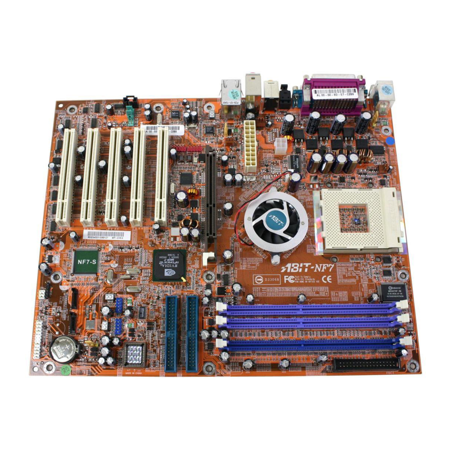
Page 8: Layout Diagram (Nf7/Nf7-S)
Chapter 1 1-2. Layout Diagram (NF7/NF7-S) NF7 Series... -
Page 9: Layout Diagram (Nf7-M)
Introduction 1-3. Layout Diagram (NF7-M) User’s Manual... -
Page 10: Layout Diagram (Nf7-S2/Nf7-S2G, Ver. 0.22)
Chapter 1 1-4. Layout Diagram (NF7-S2/NF7-S2G, Ver. 0.22) NF7 Series... -
Page 11: Chapter 2. Hardware Setup
Hardware Setup Chapter 2. Hardware Setup Before the Installation: Turn off the power supply switch (fully turn off the +5V standby power), or disconnect the power cord before installing or unplugging any connectors or add-on cards. Failing to do so may cause the motherboard components or add-on cards to malfunction or damaged. 2-1. - Page 12 CPU socket. 6. Attach the fan connector of Heatsink & Fan Assembly with the fan connector on the motherboard. ATTENTION: Do not forget to set the correct bus frequency and multiple for your processor. NF7 Series...
-
Page 13: Install System Memory
Hardware Setup 2-3. Install System Memory This motherboard provides 3 184-pin DDR DIMM sites for memory expansion available from minimum 64MB to maximum 3GB. Table 2-1. Valid Memory Configurations Bank Memory Module Total Memory Bank 0, 1 (DIMM1) 64, 128, 256, 512MB, 1GB 64MB ~ 1GB Bank 2, 3 (DIMM2) 64, 128, 256, 512MB, 1GB... -
Page 14: Connectors, Headers And Switches
This motherboard provides two power connectors to connect to an ATX12V power supply. NF7/NF7-S/NF7-M: NF7-S2/NF7-S2G: NOTE: It is recommended to connect to a power supply with 350W, 20A +5VDC capacity at least for heavily loaded system, and 2A +5VSB capacity at least for supporting wake-up features. NF7 Series... -
Page 15: Fan Connectors
CPU fan. • CPUFAN1: CPU Fan • CHAFAN1/SYSFAN1: System Fan • PWRFAN1: Auxiliary Fan (NF7/NF7-S/NF7-M) • NBFAN1: Chipset Fan (NF7-S2/NF7-S2G) WARNING: These fan connectors are not jumpers. DO NOT place jumper caps on these connectors. NF7/NF7-S/NF7-M: NF7-S2/NF7-S2G:... -
Page 16: Cmos Memory Clearing Header
• Pin 2-3 shorted: Clear CMOS memory. WARNING: Turn the power off first (including the +5V standby power) before clearing the CMOS memory. Failing to do so may cause your system to work abnormally or malfunction. NF7/NF7-S/NF7-M: NF7-S2/NF7-S2G: NF7 Series... -
Page 17: Wake-Up Header
Hardware Setup (4). Wake-up Header These headers use a jumper cap to enable/disable the wake-up function. NF7/NF7-S/NF7-M: • KBPWR1: Pin 1-2 shorted (default): Enable wake-up function support at Keyboard/Mouse port. Pin 2-3 shorted: Disable wake-up function support at Keyboard/Mouse port. - Page 18 Chapter 2 NF7-S2/NF7-S2G (Ver. 0.22): • KBPWR1: Pin 1-2 shorted (default): Disable wake-up function support at Keyboard/Mouse port. Pin 2-3 shorted: Enable wake-up function support at Keyboard/Mouse port. • USBPWR1: Pin 1-2 shorted: Disable wake-up function support at USB2 port.
-
Page 19: Front Panel Switches & Indicators Headers
LED connection. Please pay attention to connect these headers. A wrong orientation will only cause the LED not lighting, but a wrong connection of the switches could cause system malfunction. NF7/NF7-S/NF7-M: NF7-S2/NF7-S2G: • HLED (Pin 1, 3): Connects to the HDD LED cable of chassis front panel. -
Page 20: Infrared Device Header (Nf7/Nf7-S/Nf7-M)
2-10 Chapter 2 (6). Infrared Device Header (NF7/NF7-S/NF7-M) This header connects to an optional IR device attached to chassis. This motherboard supports standard IR transfer rates. NF7 Series... -
Page 21: Additional Usb Port Headers
Hardware Setup 2-11 (7). Additional USB Port Headers These headers each provide 2 additional USB 2.0 ports connection through an USB cable designed for USB 2.0 specifications. NF7/NF7-S/NF7-M: NF7-S2/NF7-S2G: Pin Assignment Pin Assignment NF7/NF7-S/NF7-M NF7-S2/NF7-S2G Data0 - Data1 - Data0 +... -
Page 22: Additional Ieee1394 Port Headers (Nf7-S)
2-12 Chapter 2 (8). Additional IEEE1394 Port Headers (NF7-S) These headers each provide one additional IEEE1394 port connection through an extension cable and bracket. Pin Assignment Pin Assignment TPA0 + TPA0 - TPB0 + TPB0 - +12V +12V NF7 Series... -
Page 23: Front Panel Audio Connection Header
• To use the audio connector at rear panel, disconnect the extension cable, attach the jumpers back at pin 5-6, and pin 9-10 (default setting). NF7/NF7-S/NF7-M: Pin Assignment Pin Assignment Audio Mic. - Page 24 2-14 Chapter 2 NF7-S2/NF7-S2G: Pin Assignment Pin Assignment Audio Mic. Ground Audio Mic. Bias Speaker Out Right Speaker Out Right Channel Channel Return Speaker Out Left Speaker Out Left Channel Channel Return NF7 Series...
-
Page 25: Internal Audio Connectors
Hardware Setup 2-15 (10). Internal Audio Connectors This connector connects to the audio output of internal CD-ROM drive or add-on card. NF7/NF7-S/NF7-M: NF7-S2/NF7-S2G: User’s Manual... -
Page 26: Accelerated Graphics Port Slot
Chapter 2 (11). Accelerated Graphics Port Slot This slot supports an optional AGP graphics card up to AGP 8X mode. ATTENTION: This motherboard does not support 3.3V AGP cards. Use only 1.5V or 0.8V AGP cards. NF7/NF7-S/NF7-M: NF7-S2/NF7-S2G: NF7 Series... -
Page 27: Floppy Disk Drive Connector
2. Install the other end(s) of ribbon cable into the disk drive connector(s). The colored edge of the ribbon cable should be also aligned with pin-1 of disk drive connector. The endmost connector should be attached to the drive designated as Drive A. NF7/NF7-S/NF7-M: NF7-S2/NF7-S2G: User’s Manual... -
Page 28: Ide Connectors
Slave”. The first drive connected to IDE2 is referred to as “Secondary Master” and the second drive as “Secondary Slave”. Keep away from connecting one legacy slow speed drive, like CD-ROM, together with another hard drive on the same IDE channel; this will drop your integral system performance. NF7/NF7-S/NF7-M: NF7 Series... - Page 29 Hardware Setup 2-19 NF7-S2/NF7-S2G: User’s Manual...
-
Page 30: Serial Ata Connectors (Nf7-S/Nf7-S2/Nf7-S2G)
2-20 Chapter 2 (14). Serial ATA Connectors (NF7-S/NF7-S2/NF7-S2G) These connectors are provided to attach one Serial ATA device at each channel via Serial ATA cable. NF7-S: SATA1 and SATA2 are controlled by Silicon Image PCI Chip. To enable the SATA1 and SATA2 controller, the item “Serial ATA Controller”... -
Page 31: Status Indicators
Hardware Setup 2-21 (15). Status Indicators • LED1 (5VSB): This LED lights up when the power supply is connected with power source. • LED2 (VCC): This LED lights up when the system power is on. NF7/NF7-S/NF7-M: NF7-S2/NF7-S2G: User’s Manual... -
Page 32: System Management Bus Headers
C is a multi-master bus, which means that multiple chips can be connected to the same bus and each one can act as a master by initiating a data transfer. If more than one master simultaneously tries to control the bus, an arbitration procedure decides which master gets priority. NF7/NF7-S/NF7-M: NF7 Series... -
Page 33: Back Panel Connectors
• COM2: Connects to external modem, mouse or other devices that support this communication protocol. (NF7/NF7-S) • VGA1: Connects to monitor input. (NF7-M) • OPT1: This connector provides an S/PDIF out connection through optical fiber to digital multimedia devices. (NF7/NF7-S/NF7-M) - Page 34 F.L./F.R. (Front Left / Front Right): Connects to the front left and front right channel in the 5.1-channel or regular 2-channel audio system. • LAN: Connects to Local Area Network. • U1/USB1/USB2 (USB Port Connectors): Connects to USB devices such as scanner, digital speakers, monitor, mouse, keyboard, hub, digital camera, joystick etc. NF7 Series...
-
Page 35: Chapter 3. Bios Setup
BIOS Setup Chapter 3. BIOS Setup This motherboard provides a programmable EEPROM that you can update the BIOS utility. The BIOS (Basic Input/Output System) is a program that deals with the basic level of communication between processor and peripherals. Use the BIOS Setup program only when installing motherboard, reconfiguring system, or prompted to “Run Setup”. -
Page 36: Softmenu Setup
Chapter 3 3-1. SoftMenu Setup The SoftMenu utility is ABIT’s exclusive and ultimate solution in programming the CPU operating speed. All the parameters regarding CPU FSB speed, multiplier factor, the AGP & PCI clock, and even the CPU core voltage are all available at your fingertips. - Page 37 BIOS Setup Multiplier Factor: This item sets the multiplier factor for the CPU you installed. NOTE: Some processors might have this multiplier factor locked, so there is no way to choose a higher multiplier factor. AGP Frequency: This item allows you to set the AGP clock speed from 66MHz to 99MHz. Due to the AGP specification limit, the speed you set over its standard clock speed is supported, but not guaranteed.
- Page 38 Chapter 3 For NF7-S2/NF7-S2G: Brand Name: This item displays the CPU model name, for example: AMD Athlon(tm) XP. Frequency: This item displays the CPU internal clock speed. System Performance: Four options are available: Optimal Aggressive Turbo Expert. The default setting is Optimal.
- Page 39 BIOS Setup Row-active delay: Fifteen options are available: from 1 to 15. This option specifies the row active time. This is the minimum number of cycles between an activate command and a precharge command to the same bank. RAS-to-CAS delay: Seven options are available: from 1 to 7.
-
Page 40: Standard Cmos Features
This item sets the time you specify (usually the current time) in the format of [Hour], [Minute], and [Second]. IDE Primary/Channel 1 Master/Slave, IDE Secondary/Channel 2 Master/Slave, IDE Channel 3/4 Master: Click <Enter> key to enter its submenu: NF7 Series... - Page 41 BIOS Setup NF7/NF7-S/NF7-M: NF7-S2/NF7-S2G: IDE HDD Auto-Detection: This item allows you to detect the parameters of IDE drives by pressing <Enter> key. The parameters will be shown on the screen automatically. IDE Primary/Channel 1 Master/Slave, IDE Secondary/Channel 2 Master/Slave, IDE Channel 3/4 Master: When set to [Auto], the BIOS will automatically check what kind of IDE drive you are using.
- Page 42 [No Errors]: The system-boot will not stop for any error detected. [All, But Keyboard]: The system-boot will stop for all errors except a keyboard error. [All, But Diskette]: The system-boot will stop for all errors except a diskette error. NF7 Series...
- Page 43 BIOS Setup [All, But Disk/Key]: The system-boot will stop for all errors except a diskette or keyboard error. Base Memory: This item displays the amount of base memory installed in the system. The value of the base memory is typically 640K for system with 640K or more memory size installed on the motherboard. Extended Memory: This item displays the amount of extended memory detected during system boot-up.
-
Page 44: Advanced Bios Features
Chapter 3 3-3. Advanced BIOS Features Hard Disk Boot Priority: (NF7-S2/NF7-S2G) This item selects the hard disks booting priority. By pressing <Enter> key, you can enter its submenu where the hard disks detected can be selected for the booting sequence to boot up system. - Page 45 BIOS Setup 3-11 sequence of the drive selected. Set [Boot Other Device] to [Enabled] if you wish to boot from another device other than these three items. Swap Floppy Drive: This item can be set as Disabled or Enabled. The default setting is Disabled. When this feature is enabled, you don’t need to open the computer case to swap the position of floppy disk drive connectors.
- Page 46 This item allows the BIOS to support some old or special IDE devices by prolonging this delay time. A larger value will give more delay time to the device for which to initialize and to prepare for activation. Full Screen LOGO Show: (NF7-S2/NF7-S2G) This item determines to show the full screen logo when booting.
-
Page 47: Advanced Chipset Features
BIOS Setup 3-13 3-4. Advanced Chipset Features For NF7/NF7-S/NF7-M: Memory Timings: Five options are available: Optimal Aggressive Turbo By SPD Expert. The default setting is Optimal. Choose Optimal for better memory compatibility; choose Aggressive/Turbo for better memory performance; choose Expert for user-define. When set to By SPD, the BIOS will read the DRAM module SPD data and automatically set to the values stored in it. - Page 48 This option specifies the amount of system memory that can be used by the AGP device. The aperture is a portion of the PCI memory address range dedicated for graphics memory address space. Frame Buffer Size: (For NF7-M only) Six options are available: 8M 128M Disabled.
- Page 49 BIOS Setup 3-15 For NF7-S2/NF7-S2G: AGP Aperture Size (MB): This option specifies the amount of system memory that can be used by the AGP device. The aperture is a portion of the PCI memory address range dedicated for graphics memory address space.
-
Page 50: Integrated Peripherals
3-16 Chapter 3 3-5. Integrated Peripherals For NF7/NF7-S/NF7-M: OnChip IDE Device: Click <Enter> key to enter its submenu: OnChip IDE1 Controller: This item allows you to enable or disable the primary and secondary IDE controller. Select [Disabled] if you want to add a different hard drive controller. - Page 51 BIOS Setup 3-17 [Auto]: The BIOS will select the best available option after checking your hard drive or CD-ROM. [Disabled]: The BIOS will not detect these categories. If problem arises in using Ultra DMA devices, try disabling this item. OnChip IDE2 Controller: The description is same as the OnChip IDE1 Controller.
- Page 52 IEEE1394 Controller (For NF7-S Only): This option enables or disables the IEEE 1394 controller. Back to Integrated Peripherals Setup Menu: Onboard PCI Device (For NF7-S Only): Click <Enter> key to enter its submenu: Serial ATA Controller: This option enables or disables the onboard Silicon Image SIL3112A SATA controller.
- Page 53 RxD and TxD. We set it to “Hi, Lo”. If your motherboard BIOS uses “No” and “Yes” to represent this item, you should set it to the same setting as the NF7/NF7-M/NF7-S. This means that you should set it to “No, Yes” in order to match the transfer and receiving speed. If you fail to do so, you will not get an IR connection between the NF7/NF7-M/NF7-S and the other computer.
- Page 54 3. The default setting is 3. When the mode selected for the parallel port mode is ECP, the DMA channel selected can be Channel 1 or Channel 3. For NF7-S2/NF7-S2G: IDE Function Setup: Click <Enter> key to enter its submenu: IDE RAID: This item allows you to enable or disable the IDE RAID function.
- Page 55 BIOS Setup 3-21 Back to Integrated Peripherals Setup Menu: Onboard Device: Click <Enter> key to enter its submenu: LAN Controller: This option enables or disables the LAN controller. LAN Boot ROM: This item allows you to use the boot ROM (instead of a disk drive) to boot-up the system and access the local area network directly.
- Page 56 This item allows you to select [BIOS] for using USB mouse in DOS environment, or [OS] in OS environment. USB2.0 Device Compatible: This item enables or disables the compatibility with USB2.0 devices. Serial-ATA: This option enables or disables the OnChip SATA controller. NF7 Series...
- Page 57 BIOS Setup 3-23 SATA Spread Spectrum: Two options are available: Enabled and Disabled. The default setting is Disabled. You can enable or disable the SATA spread spectrum. Audio Controller: This option enables or disables the audio controller. Back to Integrated Peripherals Setup Menu: SuperIO Device: Click <Enter>...
- Page 58 Init Display First: This item selects to initialize AGP or PCI Slot first when the system boots. [PCI Slot]: When the system boots, it will first initialize PCI. [AGP]: When the system boots, it will first initialize AGP. NF7 Series...
-
Page 59: Power Management Setup
Two options are available: Disabled or Enabled. The default setting is Disabled. When set to Enabled, any event affecting from Modem Ring will awaken a system that has powered down. Wakeup by Alarm: (NF7/NF7-S/NF7-M) Two options are available: Disabled or Enabled. The default setting is Disabled. When set to Enabled, you can set the date and time at which the RTC (real-time clock) alarm awakens the system from Suspend mode. - Page 60 3-26 Chapter 3 USB Resume from S3/S4: (NF7-S2/NF7-S2G) When set to [Enabled], this item allows you to use a USB device to wake up a system that is in the S3/S4 state. Power-On by Alarm: (NF7-S2/NF7-S2G) Two options are available: Disabled or Enabled. The default setting is Disabled. When set to Enabled, you can set the date and time at which the RTC (real-time clock) alarm awakens the system from Suspend mode.
- Page 61 BIOS Setup 3-27 Restore on AC Power Loss: This item selects the system action after an AC power failure. [Power Off]: When power returns after an AC power failure, the system’s power remains off. You must press the Power button to power-on the system. [Power On]: When power returns after an AC power failure, the system’s power will be powered on automatically.
-
Page 62: Pnp/Pci Configurations
[Auto(ESCD)]: The system will automatically detect the settings. [Manual]: Choose the specific IRQ resources in the “IRQ Resources” menu. IRQ Resources: Click <Enter> key to enter its submenu: This item sets each system interrupt to either [PCI Device] or [Reserved]. NF7 Series... - Page 63 BIOS Setup 3-29 Back to PnP/PCI Configurations Setup Menu: PCI/VGA Palette Snoop: This item determines whether the MPEG ISA/VESA VGA cards can work with PCI/VGA or not. [Disabled]: MPEG ISA/VESA VGA cards do not work with PCI/VGA. [Enabled]: MPEG ISA/VESA VGA cards work with PCI/VGA. Allocate IRQ to Video: This item assigns an IRQ for the VGA card installed.
- Page 64 This item determines whether the MPEG ISA/VESA VGA cards can work with PCI/VGA or not. [Disabled]: MPEG ISA/VESA VGA cards do not work with PCI/VGA. [Enabled]: MPEG ISA/VESA VGA cards work with PCI/VGA. Assign IRQ for VGA: This item assigns an IRQ for the VGA card installed. NF7 Series...
- Page 65 BIOS Setup 3-31 [Enabled]: Automatically assign an IRQ for the VGA card installed. [Disabled]: The IRQ that was previously occupied by the VGA card will be available for new device. Assign IRQ for USB: This item assigns an IRQ for the USB device connected. [Enabled]: Automatically assign an IRQ for the USB device connected.
-
Page 66: Pc Health Status
NF7/NF7-S/NF7-M: NF7-S2/NF7-S2G: Shutdown When CPUFAN Fail: (NF7/NF7-S/NF7-M) Two options are available: Disabled or Enabled. The default setting is Disabled. If you set it to Enabled, if CPUFAN out of order, system will force to shutdown to protect the processor not overheat. -
Page 67: Load Fail-Safe Defaults
BIOS Setup 3-33 All Voltages, Fans Speed and Thermal Monitoring: These unchangeable items list the current status of the CPU and environment temperatures, fan speeds, and system power voltage. NOTE: The hardware monitoring features for temperatures, fans and voltages will occupy the I/O address from 294H to 297H. - Page 68 3-34 3-34 Chapter 3 Chapter 3 NF7 Series NF7 Series...
-
Page 69: Appendix A. Install Nvidia Nforce Chipset Driver
Install NVIDIA nForce Chipset Driver Appendix A. Install NVIDIA nForce Chipset Driver NOTE: Please install this NVIDIA nForce Chipset driver first after having installed the Windows operating system. The installation procedures and screen shots in this section are based on Windows XP operating system. - Page 70 Appendix A Click [Continue Anyway]. Click [Continue Anyway]. 8. Choose [Yes, I want to restart my computer now.], and click [Finish] to complete setup. NF7 Series...
-
Page 71: Appendix B. Install Integrated Gpu Driver (Nf7-M
Install Integrated GPU Driver (NF7-M) Appendix B. Install Integrated GPU Driver (NF7-M) The installation procedures and screen shots in this section are based on Windows XP operating system. For those of other OS, please follow its on-screen instruction. Insert the Driver & Utility CD into CD-ROM drive, it should execute the installation program automatically. - Page 72 Appendix B NF7 Series...
-
Page 73: Appendix C. Install Usb 2.0 Driver
Install USB 2.0 Driver Appendix C. Install USB 2.0 Driver NOTE: The “USB 2.0 Driver” packed in the “Driver & Utility CD” is currently available for Windows 9x and ME only. To install this driver for Windows XP or Windows 2000, you have to download their latest service pack first from Microsoft’s web site. - Page 74 Appendix C NF7 Series...
-
Page 75: Appendix D. Install Lan Driver (Nf7-S2G
Install LAN Driver (NF7-S2G) Appendix D. Install LAN Driver (NF7-S2G) To install the LAN driver, please insert the Driver & Utility CD into CD-ROM drive. It should execute the installation program automatically. If not, double-click the execution file at the main directory of this CD to enter the installation menu. - Page 76 Appendix D NF7 Series...
-
Page 77: Appendix E. Install Serial Ata Driver (Nf7-S
Install Serial ATA Driver (NF7-S) Appendix E. Install Serial ATA Driver (NF7-S) The installation procedures and screen shots in this section are based on Windows XP operating system. For those of other OS, please follow its on-screen instruction. Insert the Driver & Utility CD into CD-ROM drive, it should execute the installation program automatically. - Page 78 7. Choose [Yes, I want to restart my computer For more information on how to operate, please now.], and click [Finish] to complete setup. refer to the “Help” menu. 8. Check [Device Manager]. [Silicon Image SiI 3112 SATARaid Controller] is successfully installed. NF7 Series...
-
Page 79: Raid Configuration Utility Menu
RAID array. If you want to create a RAID 1 (mirroring) array, NF7-S supports Striped (RAID 0) and Mirrored please make sure which hard disk is the source (RAID 1) RAID set. For the striped RAID set, disk and which one is the destination disk. - Page 80 “Resolve Conflict”. The correct metadata, including correct drive connection information, will then be written to the replacement disk. NOTE: For more information on RAID function, please refer to the RAID Management Software enclosed in the CD that came packed with this motherboard. NF7 Series...
-
Page 81: Appendix F. Bios Setup For Nvraid (Nf7-S2/Nf7-S2G
BIOS Setup for NVRAID (NF7-S2/NF7-S2G) Appendix F. BIOS Setup for NVRAID (NF7-S2/NF7-S2G) The NF7-S2/NF7-S2G supports the RAID operation of “Striping (RAID 0)”, “Mirroring (RAID 1)”, “Striping/Mirroring (RAID 0+1)”, “JBOD/Spanning”. striping operation, the identical drives can read and write data in parallel to increase system performance. - Page 82 The figure shown below illustrates the Define a you make a mistake, you may copy the blank New Array window after two disks have been data to the source disk, which will result in both assigned as RAID1 array disks. hard disks becoming blank! NF7 Series...
- Page 83 BIOS Setup for NVRAID (NF7-S2/NF7-S2G) Array List The Array List window appears, where you can review the RAID arrays that you have set up. Use the arrow keys to select the array that you want to set up, then press <Enter> key.
- Page 84 Appendix F NF7 Series...
-
Page 85: Appendix G. Abit Eq (The Hardware Doctor Utility
ABIT EQ (The Hardware Doctor Utility) Appendix G. ABIT EQ (The Hardware Doctor Utility) ABIT EQ is a self-diagnostic system for PC based on motherboards designed and manufactured by ABIT Computer Corporation. It will protect PC Hardware by monitoring critical items of Power Supply Voltage, CPU &... - Page 86 Appendix G 5. Execute the ABIT EQ by entering the Windows Menu [Start] [All Programs] [ABIT] [ABIT EQ]. 6. This screen appears. ABIT EQ shows you the status of Voltage, Fan Speed, and Temperature readings as well. NF7 Series...
-
Page 87: Appendix H. Flashmenu (Bios Update Utility
ABIT FlashMenu is the most stable Windows-based BIOS flash available. No more worries from crashing. With one click of BIOS updating, ABIT users can flash their BIOS more easily and in less time. The installation procedures and screen shots in this section are based on Windows XP operating system. - Page 88 5. Execute the FlashMenu by entering the Windows Menu [Start] [All Programs] [ABIT] [FlashMenu]. 6. This FlashMenu screen appears. You can easily update the BIOS from clicking [Update From File], [One Click LiveUpdate], or [LiveUpdate Step by Step] button. NF7 Series...
-
Page 89: Appendix I. Troubleshooting (Need Assistance
Troubleshooting (Need Assistance?) Appendix I. Troubleshooting (Need Assistance?) Q & A: Q: Do I need to clear the CMOS before I use a new motherboard to assemble my new computer system? A: Yes, we highly recommend that you clear the CMOS before installing a new motherboard. Please move the CMOS jumper from its default 1-2 position to 2-3 for a few seconds, and then back. - Page 90 Sound Card Driver. Write down the Sound Card model, motherboard model, BIOS identification number on the technical support file (refer to main instructions), and describe the problem in the space provided. We will show you how to fill the “Technical Support Form”. NF7 Series...
- Page 91 To fill in this “Technical Support Form”, refer to the step-by-step instructions given below: . MODEL: Note the model number given in your user’s manual. Example: NF7/NF7-M/NF7-S/NF7-S2/NF7-S2G . Motherboard model number (REV): Note the motherboard model number labeled on the motherboard as “REV:*.**”.
-
Page 92: Technical Support Form
Technical Support Form Company Name: Phone Number: Contact Person: Fax Number: E-mail Address: Model BIOS ID # Motherboard Model No. DRIVER REV OS/Application Hardware Name Brand Specifications IDE1 IDE2 IDE1 CD-ROM-Drive IDE2 System Memory ADD-ON CARD Problem Description: NF7 Series... -
Page 93: Appendix J. How To Get Technical Support
Also please make sure you have the latest drivers from your peripheral cards makers! 3. Check the ABIT Technical Terms Guide and FAQ on our Website. We are trying to expand and make the FAQs more helpful and information rich. Let us know if you have any suggestions. - Page 94 They should have reasonable return or refund policies. How they serve you is also a good reference for your next purchase. 6. Contacting ABIT. If you feel that you need to contact ABIT directly you can send email to the ABIT technical support department. First, please contact the support team for the branch office closest to you.
- Page 95 Unit 3, 24-26 Boulton Road, Stevenage, Herts SG1 4QX, UK Tel: 44-1438-228888 Fax: 44-1438-226333 E-mail: sales@abitcomputer.co.uk Germany and Benelux (Belgium, AMOR Computer B.V. (ABIT's European Office) Jan van Riebeeckweg 15, 5928LG, Venlo, Netherlands, Luxembourg), The Netherlands France, Italy, Spain, Portugal, Greece, Denmark, Norway, Tel: 31-77-3204428...
- Page 96 Please contact the reseller from whom you bought the product. You should be able to get RMA service there. 8. Reporting Compatibility Problems to ABIT. Because of tremendous number of email messages we receive every day, we are forced to give greater weight to certain types of messages than to others.
Need help?
Do you have a question about the NF7 and is the answer not in the manual?
Questions and answers