Toshiba B-852 Owner's Manual
Hide thumbs
Also See for B-852:
- Specification sheet (2 pages) ,
- User manual (2 pages) ,
- Counter reading manual (29 pages)

Related Manuals for Toshiba B-852


Summary of Contents for Toshiba B-852
- Page 1 TOSHIBA Barcode Printer B-852 SERIES Owner’s Manual Mode d’emploi Bedienungsanleitung Manual de instrucciones Gebruikershandleiding Manuale Utente Manual do Utilizador...
- Page 2 Canada.” (for CANADA only) Copyright © 2006 < For EU Only > by TOSHIBA TEC CORPORATION TOSHIBA TEC Europe Retail Information Systems S.A. All Rights Reserved Rue de la Célidée 33 BE-1080 Brussels 570 Ohito, Izunokuni-shi, Shizuoka-ken, JAPAN...
- Page 3 TOSHIBA Barcode Printer B-852 SERIES Owner's Manual...
- Page 4 Waste Recycling information for users: Following information is only for EU-member states: The use of the crossed-out wheeled bin symbol indicates that this product may not be treated as general household waste. By ensuring this product is disposed of correctly you will help prevent potential negative consequences for the environment and human health, which could otherwise be caused by inappropriate waste handling of this product.
-
Page 5: Safety Summary
Do not attempt to effect repairs or modifications to this equipment. If a fault occurs that cannot be rectified using the procedures described in this manual, turn off the power, unplug the machine, then contact your authorised TOSHIBA TEC representative for assistance. Meanings of Each Symbol This symbol indicates warning items (including cautions). - Page 6 • Utilize our maintenance services. After purchasing the machine, contact your authorised TOSHIBA TEC representative for assistance once a year to have the inside of the machine cleaned. Otherwise, dust will build up inside the machines and may cause a fire or a malfunction. Cleaning is particularly effective before humid rainy seasons.
-
Page 7: Table Of Contents
ENGLISH VERSION EO1-33055 TABLE OF CONTENTS Page PRODUCT OVERVIEW......................E1-1 Introduction........................E1-1 Features ........................E1-1 Unpacking........................E1-1 Accessories ........................E1-2 Appearance ........................E1-3 1.5.1 Dimensions.........................E1-3 1.5.2 Front View ........................E1-3 1.5.3 Rear View ........................E1-3 1.5.4 Operation Panel......................E1-4 1.5.5 Interior ........................E1-4 Options ..........................E1-5 PRINTER SETUP ........................ - Page 8 CAUTION! 1. This manual may not be copied in whole or in part without prior written permission of TOSHIBA TEC. 2. The contents of this manual may be changed without notification.
-
Page 9: Product Overview
ENGLISH VERSION EO1-33055 1.1 Introduction 1. PRODUCT OVERVIEW Thank you for choosing the TOSHIBA B-852 series label/tag printer. 1.1 Introduction This Owner’s Manual contains from general set-up through how to confirm the printer operation using a test print, and should be read carefully to help gain maximum performance and life from your printer. -
Page 10: Accessories
Power Cord QQ (1 pc.) Power Cord QP (1 pc.) Print Head Cleaner (1 pc.) Supply Holder Unit (1 pc.) CAUTION! Be sure to use TOSHIBA TEC approved print head cleaner. Failure to do this Supply Holder Frame (L) Supply Holder Frame (R) may shorten the print head life. -
Page 11: Appearance
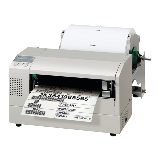
1. PRODUCT OVERVIEW ENGLISH VERSION EO1-33055 1.5 Appearance The names of the parts or units introduced in this section are used in the 1.5 Appearance following chapters. 1.5.1 Dimensions NOTE: Depth is 470 mm (18.5 inches) when the optional Cutter Module is installed on the printer. -
Page 12: Operation Panel
1. PRODUCT OVERVIEW ENGLISH VERSION EO1-33055 1.5 Appearance 1.5.4 Operation Panel LCD Message ON LINE LED Display (Green) POWER LED ERROR LED (Green) (Red) [PAUSE] key [RESTART] key [FEED] key Please see Section 3.1 for further information about the Operation Panel. 1.5.5 Interior Caution Label Supply Path Label... -
Page 13: Options
B-SA704-WLAN-QM-R Installing this PC board allows a communication by wireless LAN. Real time clock B-SA704-RTC-QM-R This module holds the current time: year, month, day, hour, minute, second NOTE: Available from your nearest TOSHIBA TEC representative or TOSHIBA TEC Head Quarters. E1- 5... -
Page 14: Printer Setup
2. PRINTER SETUP ENGLISH VERSION EO1-33055 2. PRINTER SETUP 2. PRINTER SETUP This section outlines the procedures to setup your printer prior to its operation. The section includes precautions, loading media and ribbon, connecting cables, setting the operating environment of the printer, and performing an online print test. -
Page 15: Installation
• For best results, and longer printer life, use only TOSHIBA TEC recommended media and ribbons. • Store the media and ribbons in accordance with their specifications. -
Page 16: Assembling The Accessories
Wing Bolt Supply Holder Base NOTE: 2. Attach the assembled Supply Holder Frame to the rear of the B-852 printer by inserting the hooks of the Frame into the two slots in the After attaching the supply holder rear of the printer as shown in the figure below. -
Page 17: Connecting The Power Cord
2. PRINTER SETUP ENGLISH VERSION EO1-33055 2.3 Connecting the Power Cord 2.3 Connecting the 1. Make sure that the printer power switch is in the off position. Power Cord CAUTION! 1. Make sure that the printer power switch is turned to the Power Switch off position before... -
Page 18: Loading The Media
Supply Holder Unit and adjust its position in the Supply Holder Frame at the rear of the B-852 printer. The procedure will then show the steps to properly load the media into the printer so that it feeds straight and true through the printer. - Page 19 2. PRINTER SETUP ENGLISH VERSION EO1-33055 2.4 Loading the Media 2.4.1 Installing the Media The diagram below, and the steps that follow, show the procedures for onto the Supply Holder installing the Media onto the Supply Shaft and reassembling the Supply Holder Unit.
-
Page 20: Loading Media Into The Printer
2. PRINTER SETUP ENGLISH VERSION EO1-33055 2.4 Loading the Media 1. Insert the assembled Supply Holder Unit into the rear notches of the 2.4.2 Installing the Supply Supply Holder Frame as shown in the diagram below. Holder Unit onto the Rear Notch Supply Holder Frame NOTE:... - Page 21 2. PRINTER SETUP ENGLISH VERSION EO1-33055 2.4 Loading the Media 2. Release the Print Head Block by pressing down on the Head Block 2.4.3 Loading Media into the Release Lever as shown below. Printer (Cont.) 3. Raise the Print Head Block to its fully open position as shown by the arrow in the above diagram.
- Page 22 2. PRINTER SETUP ENGLISH VERSION EO1-33055 2.4 Loading the Media 2.4.3 Loading Media into the 10. After loading the media, don’t forget to move the Supply Holder Printer (Cont.) Unit to the forward notch of the Supply Roll Frame as shown below. 11.
-
Page 23: Setting Sensor Positions
2. PRINTER SETUP ENGLISH VERSION EO1-33055 2.5 Setting Sensor Positions 2.5 Setting Sensor After loading the media, as outlined in the previous paragraphs, it will usually be necessary to set the Media Sensors used to detect the print start Positions position for label or tag printing. -
Page 24: Loading The Ribbon
2. PRINTER SETUP ENGLISH VERSION EO1-33055 2.6 Loading the Ribbon 1. Raise the Top Cover and release and raise the Print Head Block as 2.6 Loading the Ribbon described in section 2.4.3, steps 1 and 2. 2. Hold the Ribbon Supply Roll in your left hand and the Ribbon Take WARNING! up Roll in your right hand. -
Page 25: Connecting The Cables To Your Printer
2. PRINTER SETUP ENGLISH VERSION EO1-33055 2.7 Connecting the Cables to Your Printer The following paragraphs outline how to connect your host computer to Connecting the the printer, and will also show how to make cable connections to other Cables to Your devices. -
Page 26: Turning The Printer On/Off
2. PRINTER SETUP ENGLISH VERSION EO1-33055 2.8 Turning the Printer ON/OFF When the printer is connected to your host computer it is good practice to 2.8 Turning the Printer turn the printer ON before turning on your host computer and turn OFF ON/OFF your host computer before turning off the printer. -
Page 27: Setting An Operating Environment
TOSHIBA TEC service representative. For the settings this manual does not cover, please contact your nearest TOSHIBA TEC service representative, or refer to the B-852 Series Key Operation Specification. How to enter the System Mode 1. -
Page 28: Parameter Setting
2. PRINTER SETUP ENGLISH VERSION EO1-33055 2.9 Setting an Operating Environment While “<2>PARAMETER SET” is displayed on the LCD Message 2.9.1 Parameter Setting Display, press the [PAUSE] key to enter the Parameter Setting Mode. The Parameter Setting Mode contains the following sub menus. Each time the [PAUSE] key is pressed, the sub menus are displayed sequentially. - Page 29 This parameter is to choose a character code used for printing. Printed (Cont.) characters differ depending on a chosen character code and font. For details of characters, refer to the B-852 Series External Equipment Interface Specification (Printer Command Manual). NOTE: When “<2>PARAMETER SET”...
- Page 30 2. PRINTER SETUP ENGLISH VERSION EO1-33055 2.9 Setting an Operating Environment (3) Baud Rate Selection 2.9.1 Parameter Setting This parameter is to choose a baud rate of the RS-232C interface. When (Cont.) the printer communicates with a host computer by serial interface, be sure to match the setting with the host.
- Page 31 2. PRINTER SETUP ENGLISH VERSION EO1-33055 2.9 Setting an Operating Environment (5) Stop Bit Length Selection 2.9.1 Parameter Setting This parameter is to choose a stop bit length of the RS-232C interface. (Cont.) sure match setting with host computer. When “<2>PARAMETER SET” appears, press the [PAUSE] key until the following display appears.
- Page 32 2. PRINTER SETUP ENGLISH VERSION EO1-33055 2.9 Setting an Operating Environment (8) LCD Language Selection 2.9.1 Parameter Setting This parameter is to choose a language in which the LCD message is (Cont.) displayed. When “<2>PARAMETER SET” appears, press the [PAUSE] key until the following display appears.
- Page 33 2. PRINTER SETUP ENGLISH VERSION EO1-33055 2.9 Setting an Operating Environment When ON is selected, pressing the [PAUSE] key will result that the LCD 2.9.1 Parameter Setting Message Display shows the stop position fine adjustment value setting (Cont.) screen. POSITION +0.0mm POSITION +5.0mm [RESTART] POSITION +0.0mm...
- Page 34 2. PRINTER SETUP ENGLISH VERSION EO1-33055 2.9 Setting an Operating Environment After setting the control code for Control Code 1, press the [PAUSE] 2.9.1 Parameter Setting key to show the CONTROL CODE2 screen. In a same manner, press the (Cont.) [PAUSE] key after setting the control code for Control Code 2 to display the CONTROL CODE3 screen.
- Page 35 2. PRINTER SETUP ENGLISH VERSION EO1-33055 2.9 Setting an Operating Environment (12) KANJI Code Selection 2.9.1 Parameter Setting This parameter is to choose a KANJI code. (Cont.) When “<2>PARAMETER SET” appears, press the [PAUSE] key until the following display appears. NOTE: Kanji code selection is not supported KANJI CODE TYPE1...
- Page 36 2. PRINTER SETUP ENGLISH VERSION EO1-33055 2.9 Setting an Operating Environment (14) Auto Print Head Check Selection 2.9.1 Parameter Setting This parameter is to choose whether to perform the Auto Print Head (Cont.) Check function at the power on time. When “<2>PARAMETER SET” appears, press the [PAUSE] key until the following display appears.
- Page 37 2. PRINTER SETUP ENGLISH VERSION EO1-33055 2.9 Setting an Operating Environment (16) Web Printer Function Selection 2.9.1 Parameter Setting This parameter is to choose whether to use the printer as a web printer. (Cont.) When “<2>PARAMETER SET” appears, press the [PAUSE] key until the following display appears.
- Page 38 2. PRINTER SETUP ENGLISH VERSION EO1-33055 2.9 Setting an Operating Environment (18) Expansion I/O Interface Type Selection 2.9.1 Parameter Setting This parameter is to choose a type of the Expansion I/O interface (Cont.) operating mode. This parameter should be set depending on the expansion I/O control specification of the device to be connected via the expansion I/O interface.
- Page 39 2. PRINTER SETUP ENGLISH VERSION EO1-33055 2.9 Setting an Operating Environment (20) Label End/Ribbon End Selection 2.9.1 Parameter Setting This parameter is to choose a printing process when a label end or ribbon (Cont.) end is detected. When “<2>PARAMETER SET” appears, press the [PAUSE] key until the following display appears.
-
Page 40: Dump Mode Setting
2. PRINTER SETUP ENGLISH VERSION EO1-33055 2.9 Setting an Operating Environment While “<4>DUMP MODE” is displayed on the LCD Message Display, 2.9.2 Dump Mode Setting press the [PAUSE] key to enter the Dump Mode. In the Dump Mode, data in the receive buffer are printed. Data are expressed in hexadecimal values. -
Page 41: Receive Buffer Size
2. PRINTER SETUP ENGLISH VERSION EO1-33055 2.9 Setting an Operating Environment The data in the receive buffer is printed as follows: 2.9.2 Dump Mode Setting (Cont.) 00 00 00 00 00 00 00 00 00 00 00 00 00 00 00 00 00 00 00 00 00 00 00 00 00 00 00 00 00 00 00 00 00 00 00 00 00 00 00 00 00 00 00 00 00 00 00 00 7B 41 58 3B 2B 30 30 30 2C 2B 30 30 30 2C 2B 30... -
Page 42: Basic Expansion Mode
NOTE: For the BASIC enable setting mode, • The BASIC expansion mode program has already been loaded. refer to the B-852 Series Key • The BASIC enable setting mode is selected. Operation Specification stored in the CD-ROM. -
Page 43: Automatic Calibration
2. PRINTER SETUP ENGLISH VERSION EO1-33055 2.9 Setting an Operating Environment While “<6>AUTO CALIB” is displayed on the LCD Message Display, 2.9.4 Automatic Calibration press the [PAUSE] key to enter the Automatic Calibration Mode. In the Automatic Calibration Mode, whether to activate the automatic calibration at a power on time or not is selectable. -
Page 44: Lan Setting
2. PRINTER SETUP ENGLISH VERSION EO1-33055 2.9 Setting an Operating Environment While “<7>LAN” is displayed on the LCD Message Display, press the 2.9.5 LAN Setting [PAUSE] key to enter the LAN Setting Mode. In the LAN Setting Mode, whether to enable the LAN communication and SNMP or not is selectable. -
Page 45: Real Time Clock Setting
2. PRINTER SETUP ENGLISH VERSION EO1-33055 2.9 Setting an Operating Environment While “<8>RTC SET” is displayed on the LCD Message Display, press 2.9.6 Real Time Clock Setting the [PAUSE] key to enter the Real Time Clock Setting Mode. NOTE: The Real Time Clock Setting Mode contains the following sub menus. The Real Time Clock Setting is Each time the [PAUSE] key is pressed, the sub menus are displayed effective only when an optional Real... - Page 46 2. PRINTER SETUP ENGLISH VERSION EO1-33055 2.9 Setting an Operating Environment (3) Low Battery Check Setting 2.9.6 Real Time Clock Setting This parameter is to choose whether to activate the low battery check (Cont.) function or not. LOW BATT. CHECK NOTE: 1.
-
Page 47: Ip Address Setting (Tcp/Ip)
2. PRINTER SETUP ENGLISH VERSION EO1-33055 2.9 Setting an Operating Environment When the printer is connected to a PC through TCP/IP by using a LAN 2.9.7 IP Address Setting cable, it is necessary to set an IP address in the System Mode for system (TCP/IP) administrators. - Page 48 2. PRINTER SETUP ENGLISH VERSION EO1-33055 2.9 Setting an Operating Environment In this section, how to set the IP address is described. 2.9.7 IP Address Setting First, you need to access the System Mode for system administrators. (TCP/IP) (Cont.) 1. While holding down the [FEED] and [PAUSE] keys, turn on the printer.
- Page 49 2. PRINTER SETUP ENGLISH VERSION EO1-33055 2.9 Setting an Operating Environment (1) Printer IP Address 2.9.7 IP Address Setting This parameter is to set an IP address. (TCP/IP) (Cont.) PRINTER IP ADRES NOTES: [PAUSE] 1. Set each 3-digit value by using the [RESTART] or [FEED] key.
- Page 50 2. PRINTER SETUP ENGLISH VERSION EO1-33055 2.9 Setting an Operating Environment (3) Subnet Mask 2.9.7 IP Address Setting This parameter is to set a Subnet Mask. (TCP/IP) (Cont.) SUBNET MASK NOTE: After the last 3-digit value is set, [PAUSE] press the [PAUSE] key to go to 255 .
- Page 51 2. PRINTER SETUP ENGLISH VERSION EO1-33055 2.9 Setting an Operating Environment (5) DHCP 2.9.7 IP Address Setting This parameter is to enable DHCP. (TCP/IP) (Cont.) DHCP NOTE: Pressing the [PAUSE] key while [PAUSE] [RESTART] or [FEED] “DHCP ON” is displayed allows you to set a DHCP client ID.
- Page 52 Upper 4 bits Lower 4 bits “ & ‘ < > SP = Space (Example) To enter “TOSHIBA” in Hex. code: 54 4F 53 48 49 42 41 When the system mode settings have been completed, turn off the printer. E2-39...
-
Page 53: Installing The Printer Drivers
2.10 Installing the Printer Drivers 2.10.1. Introduction This manual describes how to install the TOSHIBA printer driver for the TOSHIBA bar code printer on your Windows host computer; install and delete the printer driver, the procedure for adding the LAN port, cautions and limitations. -
Page 54: Installing The Printer Driver
2. PRINTER SETUP ENGLISH VERSION EO1-33055 2.10 Installing the Printer Drivers 2.10.3. Installing the Printer Driver The installation procedure differs depending on the interface connected to the printer and the operation system you are using. Please install the printer driver by performing the appropriate procedure. If the previous version of the printer driver has been installed on your host computer , be sure to uninstall it before you install this printer driver. - Page 55 TEC B-492 B-492L-TH10-QQ TEC B-572 B-572-QQ TEC B-672 B-672-QQ B-492R-TH10-QQ B-572-QQ-US B-672-QQ-US B-492L-TH10-QP B-572-QP B-672-QP B-492R-TH10-QP TEC B-682 B-682-TS10-QQ TEC B-852 B-852-TS12-QQ TEC B-852-R B-852-TS22-QQ-R B-682-TS10-QQ-US B-852-TS12-QQ-US B-852-TS22-QP-R B-682-TS10-QP B-852-TS12-QP TEC B-872 B-872-QQ TEC B-882 B-882-TS10-QQ TEC B-SA4G B-SA4TM-GS12-QM-R B-872-QQ-US...
- Page 56 2. PRINTER SETUP ENGLISH VERSION EO1-33055 2.10 Installing the Printer Drivers (6) The screen to select the existing installed printer driver or use the new one, is displayed. Select “Replace existing driver”, then click on the [Next] button. If you install the printer driver for the first time, this screen is not displayed.
- Page 57 TEC B-492 B-492L-TH10-QQ TEC B-572 B-572-QQ TEC B-672 B-672-QQ B-492R-TH10-QQ B-572-QQ-US B-672-QQ-US B-492L-TH10-QP B-572-QP B-672-QP B-492R-TH10-QP TEC B-682 B-682-TS10-QQ TEC B-852 B-852-TS12-QQ TEC B-852-R B-852-TS22-QQ-R B-682-TS10-QQ-US B-852-TS12-QQ-US B-852-TS22-QP-R B-682-TS10-QP B-852-TS12-QP TEC B-872 B-872-QQ TEC B-882 B-882-TS10-QQ TEC B-SA4G B-SA4TM-GS12-QM-R B-872-QQ-US...
- Page 58 2. PRINTER SETUP ENGLISH VERSION EO1-33055 2.10 Installing the Printer Drivers (9) The “Use Existing Driver” screen is displayed. Select “Replace existing driver”, then click on the [Next] button. If you install the printer driver for the first time, this screen is not displayed. (10) Change the printer name if necessary, and select whether or not you use the printer as the default printer (“Yes”...
- Page 59 2. PRINTER SETUP ENGLISH VERSION EO1-33055 2.10 Installing the Printer Drivers (2) USB INTERFACE Installation starts by the operating system’s plug-and-play function. Windows 98/Me (1) Turn the printer ON, then connect it to your host computer with the USB cable. The “New Hardware Found”...
- Page 60 2. PRINTER SETUP ENGLISH VERSION EO1-33055 2.10 Installing the Printer Drivers (3) Select “Search for the best driver for your device. (Recommended)”. Mark the “Specify a location” checkbox, then click on the [Browse] button. Specify “\driver” folder, then click on the [Next] button. (4) Check to see that the “USB Printing Support”...
- Page 61 2. PRINTER SETUP ENGLISH VERSION EO1-33055 2.10 Installing the Printer Drivers (5) When the screen which indicates the USB Printing Support driver has been installed, is displayed, click on the [Finish] button. (6) After a while, “TEC B-SA4T” is detected as a new hardware. (7) The “Add New Hardware Wizard”...
- Page 62 2. PRINTER SETUP ENGLISH VERSION EO1-33055 2.10 Installing the Printer Drivers (8) Select “Search for the best driver for your device. (Recommended)”. Mark the “Specify a location” checkbox, then click on the [Browse] button. Specify “\driver” folder, then click on the [Next] button. (9) Check to see that the “TEC B-SA4T”...
- Page 63 2. PRINTER SETUP ENGLISH VERSION EO1-33055 2.10 Installing the Printer Drivers (10) Change the printer name if necessary, and select whether or not you use the printer as the default printer (“Yes” or “No”). Click on the [Finish] button. (11) When the screen, which indicates TEC B-SA4T has been installed, is displayed, click on the [Finish] button.
- Page 64 2. PRINTER SETUP ENGLISH VERSION EO1-33055 2.10 Installing the Printer Drivers Windows 2000/XP NOTE: When plug-and-play printer installation in progress is stopped, be sure to delete the printer detected and displayed on the “Device Manager” tab of the “System Properties” dialog box. (1) Log on to your host computer as a member who has full control access privilege concerning the printer settings.
- Page 65 2. PRINTER SETUP ENGLISH VERSION EO1-33055 2.10 Installing the Printer Drivers (6) Select “Install from a list or specific location (Advanced)”, then click on the [Next] button. (7) Select “Search for the best driver in these locations”. Mark the “Include this location in the search” checkbox, then click on the [Browse] button. Specify the “\driver”...
- Page 66 2. PRINTER SETUP ENGLISH VERSION EO1-33055 2.10 Installing the Printer Drivers (8) When the dialog box below is displayed, click on the [Continue Anyway] button. (9) When the “Completing the Found New Hardware Wizard” screen is displayed, click on the [Finish] button.
-
Page 67: Uninstalling The Printer Driver
2. PRINTER SETUP ENGLISH VERSION EO1-33055 2.10 Installing the Printer Drivers 2.10.4. Uninstalling the Printer Driver NOTE: Before uninstalling the printer driver, be sure to complete all of printing, the status monitor, and properties settings. Windows 98/ME (1) Select “Settings” – “Printers” from the “Start” menu to open the printer folder. (2) Right-click on the printer driver icon to be deleted, then select “Delete”. -
Page 68: Adding/Deleting A Lan Port
To use the LAN interface, first, you have to make the following settings in “<7> IP ADDRESS” in the system mode of the printer. (Refer to TOSHIBA TEC support representative.) • Set the printer IP address (“PRINTER IP ADRES”), the gateway IP address (“GATEWAY IP ADRES”), and subnet mask (“SUBNET MASK”). - Page 69 2. PRINTER SETUP ENGLISH VERSION EO1-33055 2.10 Installing the Printer Drivers Windows 2000/XP (1) Right-click on the printer icon. Select “Properties” to open the printer “Properties” dialog box. (2) Select the “Ports” tab, and click on the [Add Port…] button. The “Printer Ports” dialog box is displayed.
-
Page 70: Cautions
2. PRINTER SETUP ENGLISH VERSION EO1-33055 2.10 Installing the Printer Drivers 2.10.6 Cautions (1) Printer Driver Upgrades • To upgrade the printer driver to this version, uninstall the previous version of the printer driver, before installing this printer driver. • Be sure to restart your host computer, after you upgrade the printer driver. •... -
Page 71: Using The Printer Driver
2. PRINTER SETUP ENGLISH VERSION EO1-33055 2.10 Installing the Printer Drivers 2.10.7 Using the Printer Driver For how to use the Printer Driver, please refer to the Help for Windows Printer Drivers screen. Open the Properties screen of the Printer Driver. Clicking on the About tab causes the following screen to appear. -
Page 72: Print Test
2. PRINTER SETUP ENGLISH VERSION EO1-33055 2.11 Print Test After your operating environment has been set, perform a print test. 2.11 Print Test 1. Perform a print test by using the Printer Driver or an Issue Command. The printer driver’s Properties screen allows you to set the communication conditions, media size, and other printing conditions in accordance with your operating environment. - Page 73 Driver or TPCL (TEC Printer Command Language) in accordance with your printing condition. For details of the TPCL, refer to the B-852 Series External Equipment Interface Specification stored in the CD-ROM. Regarding how to use the Printer Driver, refer to the Help for the Windows Printer Drivers screen.
-
Page 74: Position And Print Tone Fine Adjustment
2. PRINTER SETUP ENGLISH VERSION EO1-33055 2.12 Position and Print Tone Fine Adjustment This section describes how to fine adjust a print start position, cut/strip 2.12 Position and Print position, reverse feed amount, print tone, and ribbon motor torque. Tone Fine When a fine adjustment is required, such as print start position, print tone, Adjustment etc, follow the procedure below. - Page 75 2. PRINTER SETUP ENGLISH VERSION EO1-33055 2.12 Position and Print Tone Fine Adjustment 2.12 Position and Print Print Start Position Fine Adjustment Tone Fine Adjustment (Cont.) FEED ADJ.+10.0mm FEED ADJ.+50.0mm NOTES: [RESTART] FEED ADJ.+49.9mm Choose a desired value by using the [RESTART] or [FEED] key.
- Page 76 2. PRINTER SETUP ENGLISH VERSION EO1-33055 2.12 Position and Print Tone Fine Adjustment 2.12 Position and Print Cut Position Fine Adjustment Tone Fine Adjustment (Cont.) CUT ADJ. +10.0mm CUT ADJ.+50.0mm NOTES: Choose a desired value by using the [RESTART] CUT ADJ.+49.9mm [RESTART] or [FEED] key.
- Page 77 2. PRINTER SETUP ENGLISH VERSION EO1-33055 2.12 Position and Print Tone Fine Adjustment 2.12 Position and Print Reverse Feed Amount Fine Adjustment Tone Fine Adjustment (Cont.) BACK ADJ. +5.0mm BACK ADJ.+9.9mm NOTES: Choose a desired value by using the [RESTART] BACK ADJ.+9.8 mm [RESTART] or [FEED] key.
- Page 78 2. PRINTER SETUP ENGLISH VERSION EO1-33055 2.12 Position and Print Tone Fine Adjustment 2.12 Position and Print X Coordinate Fine Adjustment Tone Fine Adjustment (Cont.) X ADJUST +5.0mm NOTES: X ADJUST +99.9mm Choose a desired value by using the [RESTART] X ADJUST +99.8mm [RESTART] or [FEED] key.
- Page 79 2. PRINTER SETUP ENGLISH VERSION EO1-33055 2.12 Position and Print Tone Fine Adjustment 2.12 Position and Print Print Tone Fine Adjustment Tone Fine Adjustment (Cont.) Thermal Transfer Print TONE ADJ.<T> +3 NOTES: Choose a desired value by using the TONE ADJ<T>. +10 Darker [RESTART] or [FEED] key.
- Page 80 2. PRINTER SETUP ENGLISH VERSION EO1-33055 2.12 Position and Print Tone Fine Adjustment 2.12 Position and Print Ribbon Motor Voltage Fine Adjustment Tone Fine When the ribbon is slack or wrinkled and printing is affected, fine adjust Adjustment (Cont.) the ribbon motor torque by using the following procedure. Take-up Motor (RBN ADJ <FW>) RBN ADJ<FW>...
-
Page 81: Threshold Setting
2.PRINTER SETUP ENGLISH VERSION EO1-33055 2.13 Threshold Setting To maintain a constant print position the printer uses the media sensor to 2.13 Threshold Setting detect a print start position according to the difference of voltage between a print area and a gap or black mark. When the media is pre-printed, the darker (or more dense) inks can interfere with this process causing paper jam errors. - Page 82 2.PRINTER SETUP ENGLISH VERSION EO1-33055 2.13 Threshold Setting 2.13 Threshold Setting Manual threshold setting procedure (Cont.) If a paper jam error still occurs even after an automatic threshold setting has been performed, manually set the threshold voltage. To make a threshold value manually set in this section effective, select the Transmissive Sensor (when using manual threshold value) or Reflective Sensor (when using manual threshold value) within software commands or the printer driver.
- Page 83 2.PRINTER SETUP ENGLISH VERSION EO1-33055 2.13 Threshold Setting When using the Black Mark Sensor 2.13 Threshold Setting (Cont.) (1) While “<5>SENSOR ADJ.” is displayed, press the [PAUSE] key until the message appears. The displayed value is a real-time voltage being detected by the Black Mark Sensor.
- Page 84 2.PRINTER SETUP ENGLISH VERSION EO1-33055 2.13 Threshold Setting Storing a “No Media Level” Voltage 2.13 Threshold Setting (Cont.) The following is how to set a “No media level” voltage that is used to detect a paper end. If a “NO PAPER” is displayed even if the media has not run out yet, this voltage needs to be set again.
- Page 85 2.PRINTER SETUP ENGLISH VERSION EO1-33055 2.13 Threshold Setting (3) Press the [PAUSE] key until the target sensor type is displayed. 2.13 Threshold Setting (Cont.) THRESHOLD<R>1.0V Black Mark Sensor [PAUSE] Feed Gap Sensor THRESHOLD<T>1.4V (4) Set a threshold voltage (calculated in Sensor Adjustment Menu) by using the [FEED] or [RESTART] key, as shown below.
-
Page 86: On Line Mode
3. ON LINE MODE ENGLISH VERSION EO1-33055 3.1 Operation Panel 3. ON LINE MODE This chapter describes usage and purpose of the keys on the Operation Panel in On Line Mode. When the printer is in On Line Mode and connected to a host computer, normal operation of printing images on labels or tags can be accomplished. -
Page 87: Operation
3. ON LINE MODE ENGLISH VERSION EO1-33055 3.2 Operation When the printer is turned on, the “ON LINE” message appears on the 3.2 Operation LCD Message Display. It is shown during standby or normal printing. 1. The printer is turned on, standing by, or printing. ON LINE 2. -
Page 88: Maintenance
4. Be sure to use the print head cleaner enclosed with this Feed Gap Sensor and Platen printer. Failure to do this may Black Mark Sensor shorten the print head life. NOTE: Please purchase the Print Head Cleaner from the authorised TOSHIBA TEC service representative. E4- 1... -
Page 89: Covers And Panels
4. MAINTENANCE ENGLISH VERSION EO1-33055 4.1 Cleaning Wipe the Cover and Front Panel with a dry soft cloth. Wipe off dirt with 4.1.2 Covers and Panels a soft cloth slightly moistened with water. CAUTION! Do not use any volatile solvent including thinner and benzene, as this may cause discoloration or distortion of the cover. -
Page 90: Troubleshooting
WARNING! If a problem cannot be solved by taking actions described in this chapter, do not attempt to repair the printer. Turn off and unplug the printer. Then contact an authorised TOSHIBA TEC service representative for assistance. 5.1 Error Messages NOTES: •... - Page 91 5. TROUBLESHOOTING ENGLISH VERSION EO1-33055 5.1 Error Messages 5.1 Error Messages (Cont.) Error Messages Problems/Cause Solutions 1. The media has run out. 1. Load new media. Then press the NO PAPER **** [RESTART] key. ⇒ Section 2.4 2. The media is not loaded properly. 2.
-
Page 92: Possible Problems
Turn the printer off and then on. If this have occurred. does not solve the problem, turn off the printer again, and call a TOSHIBA TEC authorised service representative. Possible Problems This section describes problems that may occur when using the printer, and their causes and solutions. - Page 93 5. TROUBLESHOOTING ENGLISH VERSION EO1-33055 5.2 Possible Problems Possible Problems (Cont.) Possible Problems Causes Solutions Nothing is printed on 1. The media is not loaded properly. 1. Load the media properly. ⇒ Section 2.4. the media. 2. The ribbon is not loaded properly. 2.
-
Page 94: Removing Jammed Media
5. Media jams in the Cutter Module can be caused by wear or residual If you get frequent jams in the glue from label stock on the Cutter Blade. Do not use non-specified Cutter, contact a TOSHIBA TEC media with the Cutter. authorised service representative. -
Page 95: Printer Specifications
ENGLISH VERSION EO1-33055 6. PRINTER SPECIFICATIONS 6. PRINTER SPECIFICATIONS This section describes the printer specifications. Model B-852-TS22-QQ-R B-852-TS22-QP-R Item Dimension (W × D × H) 385 mm × 181 mm* × 243 mm (15.2” × 7.1”* × 9.6”) *: Depth is 16.8” (427 mm) when the supply holder is installed. - Page 96 6. PRINTER SPECIFICATIONS ENGLISH VERSION EO1-33055 6. PRINTER SPECIFICATIONS Model B-852-TS22-QQ-R B-852-TS22-QP-R Item Available bar code types JAN8, JAN13, EAN8, EAN8+2 digits, EAN8+5 digits, EAN13, EAN13+2 digits, EAN13+5 digits, UPC-E, UPC-E+2 digits, UPC-E+5 digits, UPC-A, UPC-A+2 digits, UPC-A+5 digits, MSI,...
-
Page 97: Supply Specifications
7. SUPPLY SPECIFICATIONS 7.1 Media Please make sure that the media that will be used is approved by TOSHIBA TEC. The warranty does not apply when a problem is caused by using media that is not approved by TOSHIBA TEC. -
Page 98: Detection Area Of The Transmissive Sensor
ENGLISH VERSION EO1-33055 7.1 Media 7.1.1 Media Type (Cont.) NOTES: 1. To ensure print quality and print head life use only TOSHIBA TEC specified media. 2. When using the cutter ensure that label length plus inter-label gap length exceeds 38 mm. -
Page 99: Effective Print Area
7. SUPPLY SPECIFICATIONS ENGLISH VERSION EO1-33055 7.1 Media 7.1.4 Effective Print Area The figure below illustrates the relation between the head effective print width and media width. Out of print range Out of print range 216.8 mm±0.2 (Head Effective Print Range) 12.6mm 12.6mm 242 mm (Max. -
Page 100: Ribbon
7.2 Ribbon 7.2 Ribbon Please make sure that the ribbon being used is approved by TOSHIBA TEC. The warranty does not apply to any problem caused by using non-approved ribbons. For information regarding TOSHIBA TEC approved ribbon, please contact a sales representative. -
Page 101: Care/Handling Of Media And Ribbon
7. SUPPLY SPECIFICATIONS ENGLISH VERSION EO1-33055 7.3 Recommended Media and Ribbon Types 7.3 Recommended Media and Ribbon Types (Cont.) Ribbon type Description Vellum wax ribbon This ribbon is mainly used for vellum paper and labels. It has a very high ink density to cope with uneven printing surface Standard wax ribbon Good match for coated paper (Matt coat and glossy coat). -
Page 102: Appendix 1 Messages And Leds
APPENDIX 1 MESSAGES AND LEDS ENGLISH VERSION EO1-33055 APPENDIX 1 MESSAGES AND LEDS APPENDIX 1 MESSAGES AND LEDS Appendix 1 describes the LCD messages displayed on the operation panel. Symbols in the message : The LED is illuminated. : The LED is flashing. : The LED is unlit. - Page 103 APPENDIX 1 MESSAGES AND LEDS ENGLISH VERSION EO1-33055 APPENDIX 1 MESSAGES AND LEDS Restoration Acceptance of LED Indication by RESTART Status Request LCD Message Printer Status key Yes/No Reset Command POWER ONLINE ERROR Yes/No When the following abnormal operations are performed, a system error occurs: (a) Command fetch from an odd address (b) Access to word data at an odd...
- Page 104 The following message appears. PC001;0A00,0300, • When the error command is shown, “? (3FH)” appears for codes other than codes 20H to 7FH and A0H to DFH. • For details, please refer to the B-852 Series External Equipment Interface Specification. EA1- 3...
-
Page 105: Appendix 2 Interface
APPENDIX 2 INTERFACE ENGLISH VERSION EO1-33055 APPENDIX 2 INTERFACE APPENDIX 2 INTERFACE NOTE: To prevent radiation and reception of electrical noise, the interface cables must meet the following requirements: • In case of a parallel interface cable or serial interface cable, fully shielded and fitted with metal or metallised connector housings. - Page 106 APPENDIX 2 INTERFACE ENGLISH VERSION EO1-33055 APPENDIX 2 INTERFACE Connector: Signal PIN No. SPP Mode Nibble Mode nStrobe HostClk Data 1 Data 1 Data 2 Data 2 Data 3 Data 3 Data 4 Data 4 Data 5 Data 5 Data 6 Data 6 Data 7 Data 7...
- Page 107 APPENDIX 2 INTERFACE ENGLISH VERSION EO1-33055 APPENDIX 2 INTERFACE USB interface Standard: Conforming to V2.0 Full speed Transfer type: Control transfer, Bulk transfer Transfer rate: Full speed (12M bps) Class: Printer class Control mode: Status with the receive buffer free space information Number of ports: Power source: Self power...
- Page 108 APPENDIX 2 INTERFACE ENGLISH VERSION EO1-33055 APPENDIX 2 INTERFACE Serial interface (Option: B-SA704-RS-QM-R) Type: RS-232C Communication mode: Full duplex Transmission speed: 2400 bps, 4800 bps, 9600 bps, 19200 bps, 38400 bps, 115200 bps Synchronization: Start-stop synchronization Start bit: 1 bit Stop bit 1 bit, 2 bit Data length:...
- Page 109 Default subnet mask: 255.255.255.0 NOTE: MAC address of the Wireless LAN module will be necessary when setting the MAC address filtering function of an access point. Please ask a service person of your nearest TOSHIBA TEC service representative. EA2- 5...
- Page 110 APPENDIX 2 INTERFACE ENGLISH VERSION EO1-33055 APPENDIX 2 INTERFACE Expansion I/O Interface (Option: B-SA704-IO-QM-R) Input Signal IN0 to IN5 Output Signal OUT0 to OUT6 Connector FCN-781P024-G/P or equivalent (External Device Side) Connector FCN-685J0024 or equivalent (Printer Side) Signal Function Signal Function Input FEED...
-
Page 111: Appendix 3 Print Samples
APPENDIX 3 PRINT SAMPLES ENGLISH VERSION EO1-33055 APPENDIX 3 PRINT SAMPLES APPENDIX 3 PRINT SAMPLES Font EA3- 1... - Page 112 APPENDIX 3 PRINT SAMPLES ENGLISH VERSION EO1-33055 APPENDIX 3 PRINT SAMPLES APPENDIX 3 PRINT SAMPLES (Cont.) Bar codes 0: JAN8, EAN8 1: MSI 2: Interleaved 2 of 5 3: CODE39 (Standard) 4: NW7 5: JAN13, EAN13 6: UPC-E 7: EAN13+2 digits 8: EAN13+5 digits A:CODE128 B: CODE39 (Full ASCII)
- Page 113 APPENDIX 3 PRINT SAMPLES ENGLISH VERSION EO1-33055 APPENDIX 3 PRINT SAMPLES APPENDIX 3 PRINT SAMPLES (Cont.) K: UPC-A L: UPC-A+2 digits M: UPC-A+5 digits N: UCC/EAN128 O: Industrial 2 of 5 P: PDF417 Q: Data Matrix R: Customer bar code S: Customer bar code of high priority T: QR code U: POSTNET...
-
Page 114: Appendix 4 Glossaries
Expansion I/O interface other designs have been already printed. An optional interface circuit that may be installed into the B-852 printer to allow the printer to be Print head element connected to an external device such as a wrapping The thermal print head consists of a single line of... - Page 115 APPENDIX 4 GLOSSARIES ENGLISH VERSION EO1-33055 APPENDIX 4 GLOSSARIES Print speed Threshold setting The speed at which printing occurs. This speed is A sensor setting operation to have the printer expressed in units of ips (inches per second). maintain a constant print position of pre-printed media.
-
Page 116: Index
INDEX ENGLISH VERSION EO1-33055 INDEX INDEX Backing paper 7-1 Label 2-9, 7-1, 7-2, A4-1 Bar code 6-2, A3-2, A4-1 Label length 7-1 Batch mode 7-1, A4-1 LAN interface 6-2 Black mark 2-10, 7-1, 7-2, A4-1 LCD language 2-19 Black mark length 7-1 LCD message display 1-3, 1-4, 3-1, 6-1, A1-2 Black mark sensor 1-4, 2-10, 2-68, 2-72, 4-1, A4-1 Media 2-5, 7-1, 7-5, A4-1... - Page 117 INDEX ENGLISH VERSION EO1-33055 INDEX Sensor adjust gear 2-10 Serial interface 1-3, A2-4 Serial interface board 1-1, 1-5, 6-2 Socket port 2-37 Subnet mask 2-37 Supply Holder Frame 1-2, 1-3, 2-3, 2-7 Supply Holder Locking Knob 2-5, 2-6 Supply Holder Unit 1-2, 1-3, 2-5, 2-7 Tag 2-9, 2-10, 7-1, A4-2 Thermal direct 2-66, 6-1, A4-2 Thermal transfer 2-66, 6-1, A4-2...
- Page 118 EO1-33055D...
Need help?
Do you have a question about the B-852 and is the answer not in the manual?
Questions and answers