Gateway 450ROG Service Manual
Hide thumbs
Also See for 450ROG:
- User manual (322 pages) ,
- Replacement instructions manual (12 pages) ,
- Specifications (11 pages)
Table of Contents
Advertisement
Advertisement
Table of Contents

Subscribe to Our Youtube Channel
Related Manuals for Gateway 450ROG


Summary of Contents for Gateway 450ROG
- Page 1 Gateway 450 Notebook serviceguide Customizing Troubleshooting...
-
Page 3: Table Of Contents
Contents 1 Replacing Gateway 450ROG Components ..... . . 1 Identifying the notebook model ......... 2 Identifying components . -
Page 5: Replacing Gateway 450Rog Components
© 2003 Gateway, Inc. All rights reserved. Gateway, Gateway Country, the Gateway stylized logo, and the black-and-white spot design are trademarks or registered trademarks of Gateway, Inc. in the United States and other countries. All other brands and product names are trademarks or registered trademarks of their respective... - Page 6 Thank you for purchasing this Factory Service Manual CD/DVD from servicemanuals4u.com. Please check out our eBay auctions for more great deals on Factory Service Manuals: servicemanuals4u...
-
Page 7: Identifying The Notebook Model
Replacing Gateway 450ROG Components Identifying the notebook model The label on the bottom of the notebook contains information that identifies the notebook model and its features. Gateway model number Warning It is important that you use the correct service guide for the notebook. -
Page 8: Identifying Components
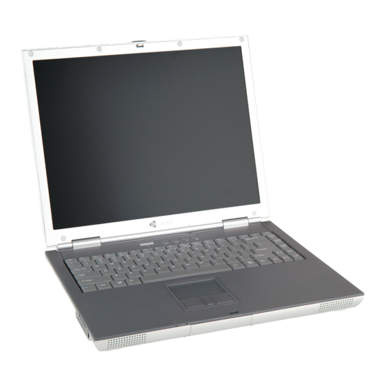
Use this chart to identify the main components of the notebook. For a complete list of replaceable parts, see the Contents. LCD panel assembly (see page Keyboard cover (see page Keyboard (see page Cooling assembly (see page Palm rest assembly (see page System board (see page www.gateway.com... -
Page 9: Preparing Your Work Space
Replacing Gateway 450ROG Components Preparing your work space Before performing maintenance on the notebook, make sure that your work space and the notebook are correctly prepared. ■ Wear a grounding (ESD) wrist strap, and use a grounded or dissipative work mat. -
Page 10: Preventing Static Electricity Discharge
Touch a bare metal surface on your workbench or other grounded object. ■ Unplug the power cord and the modem and network cables. ■ Remove the main and optional secondary batteries. For more information, “Removing the batteries” on page ■ Disconnect all peripheral devices and remove any PC Cards. www.gateway.com... -
Page 11: Preparing The Notebook
Replacing Gateway 450ROG Components Before working with notebook components, follow these guidelines: ■ Avoid static-causing surfaces such as carpeted floors, plastic, and packing foam. ■ Remove components from their antistatic bags only when you are ready to use them. Do not lay components on the outside of antistatic bags because only the inside of the bags provide electrostatic protection. -
Page 12: Disconnecting From The Port Replicator
Disconnecting from the port replicator Disconnecting from the port replicator To separate the notebook from the port replicator: Press down on both docking release latches. The notebook will spring up slightly. Lift the notebook off of the port replicator. www.gateway.com... -
Page 13: Removing The Batteries
Replacing Gateway 450ROG Components Removing the batteries Removing the main battery To remove the main battery: Disconnect the AC adapter and modem and network cables and prepare the notebook by following the instructions in “Preparing the notebook” on page Disconnect the notebook from the optional port replicator by following the instructions in “Disconnecting from the port replicator”... -
Page 14: Removing The Optional Secondary Battery
“Disconnecting from the port replicator” on page Turn the notebook over so the bottom is facing up. Slide and hold the modular bay latch closest to the back of the notebook. Slide the other modular bay release latch. The battery moves out slightly. www.gateway.com... - Page 15 Replacing Gateway 450ROG Components Slide the battery out. www.gateway.com...
-
Page 16: Adding Or Replacing Memory Modules
Adding or replacing memory modules Adding or replacing memory modules Tools you need to complete this task: Phillips #0 screwdriver Important Use only memory modules designed for the Gateway 450ROG. Memory www.gateway.com... - Page 17 Replacing Gateway 450ROG Components To add or replace memory modules: Disconnect the AC adapter and modem and network cables and prepare the notebook by following the instructions in “Preparing the notebook” on page Disconnect the notebook from the optional port replicator by following the instructions in “Disconnecting from the port replicator”...
- Page 18 Adding or replacing memory modules If you are removing a module, gently press outward on the clip at each end of the memory module until the module tilts upward. Pull the memory module out of the slot. www.gateway.com...
- Page 19 Replacing Gateway 450ROG Components Hold the new or replacement module at a 30-degree angle and press it into the empty memory slot. This module is keyed so it can only be inserted in one direction. If the module does not fit, make sure that the notch in the module lines up with the tab in the memory slot.
-
Page 20: Replacing The Ieee 802.11 Mini Pci Card
Mini PCI card Caution By law, only approved wireless modules provided by Gateway, or a Gateway authorized representative, explicitly for the Gateway 450ROG may be installed in this notebook. Caution Legal requirements dictate that a security screw (or other means) be used to attach the mini-PCI cover to the chassis in a manner that restricts end user access. - Page 21 Replacing Gateway 450ROG Components Remove the main and optional secondary batteries by following the instructions in “Removing the batteries” on page If the mini PCI screw is covered by a wireless Ethernet label, remove the label. Use the appropriate screwdriver to loosen the captive screw that secures the mini PCI cover.
- Page 22 Replacing the IEEE 802.11 Mini PCI card Unplug the two antenna cables. Move the antenna wires out of the way, then press outward on the clip at each side of the module until the module tilts upward. www.gateway.com...
- Page 23 Replacing Gateway 450ROG Components Pull the module out of the slot. Hold the new module at a 30-degree angle and press it into the empty slot. This module is keyed so it can only be inserted in one direction. If the module does not fit, make sure that the notch in the module lines up with the tab in the module slot.
- Page 24 AUX or A. Replace the mini PCI cover, then tighten the captive screw. If the mini PCI screw was covered by a wireless Ethernet label, replace the label. www.gateway.com...
-
Page 25: Replacing The Hard Drive Kit
Replacing Gateway 450ROG Components Replacing the hard drive kit Tools you need to complete this task: Phillips #0 screwdriver Screws removed during this task: 1 chrome 2.5 × 4 mm (hard drive kit) Hard drive www.gateway.com... - Page 26 “Disconnecting from the port replicator” on page Turn the notebook over so the bottom is facing up. Remove the main and optional secondary batteries by following the instructions in “Removing the batteries” on page Remove the hard drive kit screw. www.gateway.com...
- Page 27 Replacing Gateway 450ROG Components Slide the old hard drive kit out of the notebook. Slide the new hard drive kit into the notebook. Replace the screw that secures the hard drive kit to the notebook. www.gateway.com...
-
Page 28: Replacing The Hard Drive In The Hard Drive Kit
Turn the notebook over so the bottom is facing up. Remove the main and optional secondary batteries by following the instructions in “Removing the batteries” on page Remove the hard drive kit by following the instructions in “Replacing the hard drive kit” on page www.gateway.com... - Page 29 Replacing Gateway 450ROG Components Remove the two screws that secure the hard drive to the hard drive kit bracket. Screw Screw Remove the bracket from the old drive. www.gateway.com...
- Page 30 Plastic strip Replace the two screws that secure the bracket to the drive. Slide the new hard drive kit into the notebook. Replace the screw that secures the hard drive kit to the notebook. www.gateway.com...
-
Page 31: Replacing The Keyboard Cover
Replacing Gateway 450ROG Components Replacing the keyboard cover Tools you need to complete this task: Flat-blade driver - OR - Scribe or non-marring tool To replace the keyboard cover: Disconnect the AC adapter and modem and network cables and prepare the notebook by following the instructions in “Preparing the notebook”... - Page 32 Pull the cover off the notebook. You will hear small snapping sounds as the cover comes away from the notebook. Be careful not to break off the tabs found on the left end of the cover. www.gateway.com...
- Page 33 Replacing Gateway 450ROG Components Slide the two tabs on the left end of the new cover under the notebook frame. Press down on the cover in several places until it clicks in place. The cover is correctly mounted when you can run you finger along the cover and find no loose spots.
-
Page 34: Replacing The Keyboard
Remove the main and optional secondary batteries by following the instructions in “Removing the batteries” on page Turn the notebook over so the top is facing up. Remove the keyboard cover by following the instructions in “Replacing the keyboard cover” on page www.gateway.com... - Page 35 Replacing Gateway 450ROG Components Remove the four keyboard screws that secure the keyboard to the notebook. Screws Lift the back edge of the keyboard slightly, then carefully slide the keyboard back until the four tabs on the front edge of the keyboard are free from their slots.
- Page 36 Replacing the keyboard Slowly rotate the keyboard toward you so it lies keys-down on top of the notebook. Be careful not to damage the LCD panel. www.gateway.com...
- Page 37 Replacing Gateway 450ROG Components Use two fingers to unplug the keyboard panel connector from the notebook. Be careful not to touch or damage any other components. Place the new keyboard keys-down on the notebook with the space bar away from you.
- Page 38 Insert the four tabs located on the front edge of the keyboard into the corresponding slots under the palm rest. Tabs Gently press the keyboard down until it is flat all the way across. The keyboard should easily fall into place. Be careful not to damage the LCD panel. www.gateway.com...
- Page 39 Replacing Gateway 450ROG Components Replace the four keyboard screws. Screws Reassemble the notebook. www.gateway.com...
-
Page 40: Replacing The Modem
“Removing the batteries” on page Turn the notebook over so the top is facing up. Remove the keyboard cover by following the instructions in “Replacing the keyboard cover” on page Remove the keyboard by following the instructions in “Replacing the keyboard” on page www.gateway.com... - Page 41 Replacing Gateway 450ROG Components If the notebook has IEEE 802.11 wireless networking built in, slide the antenna cables away from the LED indicator panel EMI shielding. Remove the two screws that secure the modem to the notebook. Screws www.gateway.com...
- Page 42 ¼ inch. Slide the modem toward you until it slides out from under the LED indicator panel shielding. Unplug the modem cable from the modem. Connect the modem cable into the new modem. www.gateway.com...
- Page 43 Replacing Gateway 450ROG Components Slide the modem under the LED indicator panel shielding, align the modem’s screw holes with the holes on the notebook, then press the modem into place. Replace the two screws that secure the modem to the notebook. Use the shorter screw to secure the lower-left corner.
-
Page 44: Replacing The Led Indicator Panel
“Removing the batteries” on page Turn the notebook over so the top is facing up. Remove the keyboard cover by following the instructions in “Replacing the keyboard cover” on page Remove the keyboard by following the instructions in “Replacing the keyboard” on page www.gateway.com... - Page 45 Replacing Gateway 450ROG Components If the notebook has IEEE 802.11 wireless networking built in, slide the antenna cables away from the LED indicator panel EMI shielding. Remove the three screws that secure the LED indicator panel shield to the notebook.
- Page 46 Align the new indicator panel’s screw holes with the holes on the notebook, then press the panel into place. Carefully replace the indicator panel’s shielding. Replace the three screws that secure the LED indicator panel to the notebook. Rethread the antenna cables (if applicable). Reassemble the notebook. www.gateway.com...
-
Page 47: Replacing The Cooling Assembly
Replacing Gateway 450ROG Components Replacing the cooling assembly Tools you need to complete this task: Flat-blade driver - OR - Scribe or non-marring tool Phillips #0 screwdriver Screws removed during this task: 4 chrome 2.5 × 2.5 mm 4 chrome 2.5 × 4 mm... - Page 48 Replacing the cooling assembly Unplug the cooling fan. Remove the four screws that secure the cooling assembly to the notebook. Screws Screws www.gateway.com...
- Page 49 Replacing Gateway 450ROG Components At the same time as you lift, move the cooling assembly to the front of the notebook and remove it. Insert the new cooling assembly into the notebook. Replace the four cooling assembly screws. Plug in the cooling fan.
-
Page 50: Replacing The Hinge Covers
Remove the main and optional secondary batteries by following the instructions in “Removing the batteries” on page Turn the notebook over so the top is facing up. Remove the keyboard cover by following the instructions in “Replacing the keyboard cover” on page www.gateway.com... - Page 51 Replacing Gateway 450ROG Components If you are replacing the left hinge cover, go to Step -OR- If you are replacing only the right hinge cover, go to Step Remove the keyboard by following the instructions in “Replacing the keyboard” on page Remove the cooling assembly by following the instructions in “Replacing...
-
Page 52: Replacing The Lcd Panel Assembly
If the notebook has IEEE 802.11 wireless networking built in, remove the IEEE 802.11 Mini PCI module by following the instructions in “Replacing the IEEE 802.11 Mini PCI card” on page Turn the notebook over so the top is facing up. www.gateway.com... - Page 53 Replacing Gateway 450ROG Components Remove the keyboard cover by following the instructions in “Replacing the keyboard cover” on page Remove the keyboard by following the instructions in “Replacing the keyboard” on page Remove the cooling assembly by following the instructions in “Replacing...
- Page 54 Make sure you grasp the connector, not the cable. Warning The connector is fragile. When using a flat-blade screwdriver to remove the connector, pry up one side slightly, then pry up the other side slightly. Continue alternating from side-to-side until the connector comes loose. www.gateway.com...
- Page 55 Replacing Gateway 450ROG Components Loosen the screw holding the grounding wire, then lift the LCD panel grounding wire to remove the screw. LCD panel grounding screw www.gateway.com...
- Page 56 Place the new LCD panel assembly onto the notebook, then replace the four hinge screws. Reattach the grounding cable. Thread the antenna cables through the guides on the LED indicator panel shielding, then through the hole in the system board. Plug the LCD video cable into the notebook. www.gateway.com...
- Page 57 End users are strictly prohibited from having access to the wireless card. Due to manufacturing process changes, Gateway 450ROG notebooks manufactured after August 7, 2003 require a Torx head security screw to attach the mini-PCI cover.
-
Page 58: Replacing The Palm Rest Assembly
(hard drive kit) (keyboard) (LED indicator panel) 4 chrome 2.5 × 4 mm 1 chrome 2.5 × 7 mm (cooling assembly) (grounding wire) 13 chrome 2.5 × 4 mm (bottom, palm rest) 2 chrome 2.5 × 2.5 mm (palm rest) www.gateway.com... - Page 59 Replacing Gateway 450ROG Components To replace the palm rest assembly: Disconnect the AC adapter and modem and network cables and prepare the notebook by following the instructions in “Preparing the notebook” on page Disconnect the notebook from the optional port replicator by following the instructions in “Disconnecting from the port replicator”...
- Page 60 Replacing the palm rest assembly Turn the notebook over, then remove the twelve screws on the bottom of the notebook. Screws Screws Screws Screws www.gateway.com...
- Page 61 Replacing Gateway 450ROG Components Turn the notebook over, then remove the three screws on the top of the notebook. Screws www.gateway.com...
- Page 62 Pull up on the touchpad connector to make sure that it is in the raised position. Slide the end of the touchpad cable into the touchpad connector. Important The touchpad cable should slide easily into the touchpad connector. The cable is oriented correctly if it is not twisted. www.gateway.com...
- Page 63 Replacing Gateway 450ROG Components Use two fingers to press down on the touchpad connector tabs. This locks the touchpad cable into the touchpad connector. Reassemble the notebook. www.gateway.com...
-
Page 64: Replacing The Cmos Battery
(hard drive kit) (keyboard) (LED indicator panel) 4 chrome 2.5 × 4 mm 1 chrome 2.5 × 7 mm (cooling assembly) (grounding wire) 13 chrome 2.5 × 4 mm (bottom, palm rest) 2 chrome 2.5 × 2.5 mm (palm rest) www.gateway.com... - Page 65 Replacing Gateway 450ROG Components To replace the CMOS battery: Disconnect the AC adapter and modem and network cables and prepare the notebook by following the instructions in “Preparing the notebook” on page Disconnect the notebook from the optional port replicator by following the instructions in “Disconnecting from the port replicator”...
- Page 66 Make sure the positive (+) side of the new battery is facing up, then press the battery into the socket until it snaps into place. Reassemble the notebook. www.gateway.com...
-
Page 67: Replacing The Power Board
Replacing Gateway 450ROG Components Replacing the power board Tools you need to complete this task: Flat-blade driver - OR - Scribe or non-marring tool Phillips #0 screwdriver Screws removed during this task: 1 chrome 2.5 × 4 mm 4 chrome 2.5 × 2.5 mm 3 chrome 2.5 ×... - Page 68 Unplug the LCD video cable from the notebook by following the instructions in Step 12 page Remove the screw holding the LCD grounding wire by following the instructions in Step 13 page Remove the palm rest assembly by following the instructions in “Replacing the palm rest assembly” on page www.gateway.com...
- Page 69 Replacing Gateway 450ROG Components Remove the four screws that secure the power board EMI shield to the system board. Screws Lift the shielding away from the system board. Insert the flat-blade screwdriver or non-marring tool under the power board, gently pry it up, and remove it.
- Page 70 Replacing the power board Align the new power board’s screw holes with the holes on the system board, then press the power board into place. Replace the power board’s EMI shielding, then replace the screws. Reassemble the notebook. www.gateway.com...
-
Page 71: Replacing The System Board
Replacing Gateway 450ROG Components Replacing the system board Tools you need to complete this task: Flat-blade driver - OR - Scribe or non-marring tool 5.0 mm hex nutdriver Phillips #0 screwdriver Torx T8 screwdriver www.gateway.com... - Page 72 (power board) 2 chrome 2.5 × 2.5 mm (palm rest) 9 chrome 5 × 9 mm (6 rear I/O panel and 2 chrome 5 × 11 mm 3 system board) (system board) 4 chrome 2.5 × 4 mm (system board) www.gateway.com...
- Page 73 Replacing Gateway 450ROG Components To replace the system board: Disconnect the AC adapter and modem and network cables and prepare the notebook by following the instructions in “Preparing the notebook” on page Disconnect the notebook from the optional port replicator by following the instructions in “Disconnecting from the port replicator”...
- Page 74 Remove the power board by following the instructions in “Replacing the power board” on page Unplug the speakers from the system board (one connector). Remove the six hex nuts on the rear I/O panel. Hex nuts www.gateway.com...
- Page 75 Replacing Gateway 450ROG Components Remove the four system board screws and the five system board hex nuts. Long hex nuts Screw Short hex nuts Screws www.gateway.com...
- Page 76 While pushing in on the PC Card eject button, remove the system board. Make sure that the rear I/O panel clears the bottom of the chassis (shown by the top arrow) and the side audio jacks clear the bottom of the chassis (shown by the left arrow). www.gateway.com...
- Page 77 Replacing Gateway 450ROG Components Use a flat-blade screwdriver to turn the processor lock screw ¼-turn counter-clockwise, then remove the processor from the old system board. www.gateway.com...
- Page 78 ¼-turn clockwise. Remove the modem cable from the old system board and install it on the new board. www.gateway.com...
- Page 79 Replacing Gateway 450ROG Components If the new system board does not have a hard drive kit tray, remove the hard drive kit tray from the old system board and install it on the new board. The tray is attached to the system board with adhesive as well as four tabs that protrude through the system board.
- Page 80 End users are strictly prohibited from having access to the wireless card. Due to manufacturing process changes, Gateway 450ROG notebooks manufactured after August 7, 2003 require a Torx head security screw to attach the mini-PCI cover.
- Page 81 MAN SYS 450 ROG SERVICE GDE R1 7/03...
Need help?
Do you have a question about the 450ROG and is the answer not in the manual?
Questions and answers