Compaq Evo N800c Series Service Manual
Hide thumbs
Also See for Evo N800c Series:
- Maintenance and service manual (181 pages) ,
- Troubleshooting tips (18 pages) ,
- User manual (172 pages)
Table of Contents
Advertisement
Advertisement
Chapters
Table of Contents
Troubleshooting

Related Manuals for Compaq Evo N800c Series


Summary of Contents for Compaq Evo N800c Series
- Page 1 Thank you for purchasing this Factory Service Manual CD/DVD from servicemanuals4u.com. Please check out our eBay auctions for more great deals on Factory Service Manuals: servicemanuals4u...
-
Page 2: Maintenance And Service Guide
Maintenance and Service Guide Compaq Evo Notebook N800c Series Compaq Evo Notebook N800v Series Compaq Evo Notebook N800w Series Compaq Presario 2800 Series Mobile PC Document Part Number: 268135-004 April 2003 This guide is a troubleshooting reference used for maintaining and servicing the notebook. - Page 3 © 2003 Hewlett-Packard Development Company, L.P. Microsoft and Windows are trademarks of Microsoft Corporation in the U.S. and/or other countries. Intel, Pentium, and SpeedStep are trademarks of Intel Corporation in the U.S. and/or other countries. HP shall not be liable for technical or editorial errors or omissions contained herein or for incidental or consequential damages in connection with the furnishing, performance, or use of this material.
-
Page 4: Table Of Contents
Selecting from the Advanced Menu ... . 2–5 2.2 Using Compaq Diagnostics ....2–7 Obtaining, Saving, or Printing Configuration Information . - Page 5 Contents 4 Removal and Replacement Preliminaries 4.1 Tools Required ......4–1 4.2 Service Considerations..... . . 4–2 Plastic Parts .
- Page 6 Contents 5.12 Speaker Assembly ......5–31 5.13 Display Release Assembly....5–33 5.14 TouchPad .
-
Page 7: Product Description
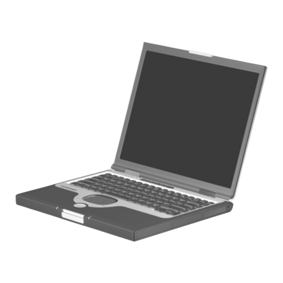
Product Description The Compaq Presario 2800 and Evo Notebook N800 Series of Personal notebooks offer advanced modularity, Intel Mobile Pentium 4 processors with SpeedStep technology with 64-bit architecture, industry-leading Accelerated Graphics Port (AGP) implementation, and extensive multimedia support. Figure 1-1. Compaq Presario 2800 and Evo Notebook N800 Maintenance and Service Guide 1–1... -
Page 8: Models
Product Description 1.1 Models Notebook models are shown in Tables 1-1 through 1-4. Table 1-1 Compaq Evo Notebook N800c, Evo Notebook N800v, Evo Notebook 800w, and Presario 2800 Model Naming Conventions N800w XXXXXX-XXX Description Options Brand/Series N = Evo Notebook... - Page 9 Product Description Table 1-2 Compaq Evo Notebook N800c Models The following Compaq Evo Notebook N800c models use config. code KLMZ and feature: ■ Dual pointing device (TouchPad and pointing stick) ■ 8-cell, 4.0 Ah lithium ion (Li ion) battery pack ■...
- Page 10 Product Description Table 1-2 Compaq Evo Notebook N800c Models (Continued) N800c Belgium 470052-816 The Netherlands 470052-826 Czech Republic 470052-817 Norway 470052-827 Denmark 470052-818 Portugal 470052-828 European 470052-819 Russia 470052-829 International Saudi Arabia 470052-815 France 470052-820 Slovenia 470052-830 Germany 470052-821 Spain...
- Page 11 Product Description Table 1-2 Compaq Evo Notebook N800c Models (Continued) N800c Belgium 470052-734 The Netherlands 470052-744 Czech Republic 470052-735 Norway 470052-745 Denmark 470052-736 Portugal 470052-746 European 470052-737 Russia 470052-747 International Saudi Arabia 470052-733 France 470052-738 Slovenia 470052-748 Germany 470052-739 Spain...
- Page 12 Product Description Table 1-2 Compaq Evo Notebook N800c Models (Continued) The following Compaq Evo Notebook N800c models use config. code KLMZ and feature: ■ Dual pointing device (TouchPad and pointing stick) ■ 8-cell, 4.0 Ah Li ion battery pack ■...
- Page 13 Product Description Table 1-2 Compaq Evo Notebook N800c Models (Continued) N800c Asia Pacific 470049-123 Latin America 470049-115 Australia 470049-117 (NAFTA) Belgium 470049-080 The Netherlands 470049-094 Brazil 470049-116 Norway 470049-096 Czech Republic 470049-081 People’s 470049-129 Denmark 470049-083 Republic European 470049-084 of China...
- Page 14 Product Description Table 1-2 Compaq Evo Notebook N800c Models (Continued) The following Compaq Evo Notebook N800c models use config. code KLMZ and feature: ■ Dual pointing device (TouchPad and pointing stick) ■ 8-cell, 4.0 Ah Li ion battery pack ■...
- Page 15 Product Description Table 1-2 Compaq Evo Notebook N800c Models (Continued) N800c Asia Pacific 470035-307 Latin America 470035-299 Australia 470035-305 (NAFTA) Brazil 470035-302 People’s 470035-308 French Canada 470035-293 Republic Hong Kong 470035-310 of China Japan 470035-295 Taiwan 470035-309 Korea 470035-319 United States...
- Page 16 Product Description Table 1-2 Compaq Evo Notebook N800c Models (Continued) N800c Asia Pacific 470035-260 Latin America 470035-254 Australia 470035-258 (NAFTA) Belgium 470035-228 The Netherlands 470035-238 Brazil 470035-256 Norway 470035-239 Czech Republic 470035-229 People’s 470035-262 Denmark 470035-230 Republic European 470035-231 of China...
- Page 17 Product Description Table 1-2 Compaq Evo Notebook N800c Models (Continued) N800c Asia Pacific 470035-033 Latin America 470035-048 Australia 470035-031 (NAFTA) Belgium 470035-008 The Netherlands 470035-018 Brazil 470035-030 Norway 470035-019 Czech Republic 470035-009 People’s 470035-035 Denmark 470035-010 Republic European 470035-011 of China...
- Page 18 Product Description Table 1-2 Compaq Evo Notebook N800c Models (Continued) N800c Asia Pacific 470035-220 Latin America 470035-217 Australia 470035-219 (NAFTA) Brazil 470035-218 People’s 470035-221 French Canada 470035-214 Republic Hong Kong 470035-223 of China Japan 470035-215 Taiwan 470035-222 Korea 470035-224 United States...
- Page 19 Product Description Table 1-3 Compaq Evo Notebook N800v Models The following Compaq Evo Notebook N800v models use config. code KSQZ and feature: ■ TouchPad pointing device ■ 8-cell, 4.4 Ah Li ion battery pack ■ 64 MB of discrete video memory ■...
- Page 20 Product Description Table 1-3 Compaq Evo Notebook N800v Models (Continued) N800v Belgium 470053-858 Norway 470056-874 Czech Republic 470053-859 Portugal 470053-875 Denmark 470053-860 Russia 470053-876 European 470053-861 Saudi Arabia 470053-877 International Slovenia 470053-857 France 470053-866 Spain 470053-878 Greece/Poland 470053-867 Sweden/Finland 470053-879...
- Page 21 Product Description Table 1-3 Compaq Evo Notebook N800v Models (Continued) N800v Belgium 470053-739 Norway 470053-754 Czech Republic 470053-740 Portugal 470053-755 Denmark 470053-746 Russia 470053-756 European 470053-747 Saudi Arabia 470053-738 International Slovenia 470053-757 France 470053-748 Spain 470053-758 Greece/Poland 470053-749 Sweden/Finland 470053-759...
- Page 22 Product Description Table 1-3 Compaq Evo Notebook N800v Models (Continued) N800v Belgium 470053-831 Norway 470053-847 Czech Republic 470053-836 Portugal 470053-848 Denmark 470053-838 Russia 470053-849 European 470053-839 Saudi Arabia 470053-850 International Slovenia 470053-830 France 470053-841 Spain 470053-851 Greece/Poland 470053-842 Sweden/Finland 470053-852...
- Page 23 Product Description Table 1-3 Compaq Evo Notebook N800v Models (Continued) N800v Belgium 470044-531 Norway 470044-541 Czech Republic 470044-532 Portugal 470044-542 Denmark 470044-533 Russia 470044-543 European 470044-534 Saudi Arabia 470044-530 International Slovenia 470044-544 France 470044-535 Spain 470044-545 Greece/Poland 470044-536 Sweden 470044-546...
- Page 24 Product Description Table 1-3 Compaq Evo Notebook N800v Models (Continued) N800v Belgium 470044-710 Norway 470044-720 Czech Republic 470044-711 Portugal 470044-721 Denmark 470044-712 Russia 470044-722 European 470044-713 Saudi Arabia 470044-707 International Slovenia 470044-723 France 470044-714 Spain 470044-724 Greece/Poland 470044-715 Sweden 470044-725...
- Page 25 Product Description Table 1-3 Compaq Evo Notebook N800v Models (Continued) N800v Belgium 470035-759 Norway 470035-779 Czech Republic 470035-760 Portugal 470035-781 Denmark 470035-763 Russia 470035-782 European 470035-768 Saudi Arabia 470035-757 International Slovakia 470035-784 France 470035-770 Spain 470035-785 Greece/Poland 470035-771 Sweden/Finland 470035-787...
- Page 26 Product Description Table 1-3 Compaq Evo Notebook N800v Models (Continued) The following Compaq Evo Notebook N800v models use config. code KSRZ and feature: ■ TouchPad ■ 8-cell, 4.4 Ah Li ion battery pack ■ 32 MB of discrete video memory ■...
- Page 27 Germany 470045-608 N800v Germany 470045-607 N800v Germany 470035-291 N800v The following Compaq Evo Notebook N800v models use config. code LLYZ and feature: ■ TouchPad ■ 8-cell, 4.4 Ah Li ion battery pack ■ 32 MB of discrete video memory ■...
- Page 28 Product Description Table 1-4 Compaq Evo Notebook N800w Models The following Compaq Evo Notebook N800w models use config. code LDF1 and feature: ■ Dual pointing device (TouchPad and pointing stick) ■ 8-cell, 4.4 Ah Li ion battery pack ■ 64 MB of discrete video memory ■...
- Page 29 Product Description Table 1-4 Compaq Evo Notebook N800w Models (Continued) N800w Asia Pacific 470043-590 Latin America 470043-587 Australia 470043-589 The Netherlands 470043-581 Belgium 470043-576 People’s 470043-591 European 470047-495 Republic International of China France 470043-578 Sweden/Finland 470051-460 Germany 470043-579 Spain 470043-583...
- Page 30 Product Description Table 1-4 Compaq Evo Notebook N800w Models (Continued) The following Compaq Evo Notebook N800w model uses config. code LMBZ and features: ■ Dual pointing device (TouchPad and pointing stick) ■ 8-cell, 4.4 Ah Li ion battery pack ■...
- Page 31 Product Description Table 1-5 Compaq Presario 2800 Models The following Compaq Presario 2800 models use config. code KSQZ and feature: ■ Diskette drive ■ TouchPad ■ 8-cell, 4.4 Ah Li ion battery pack ■ 64 MB of discrete video memory ■...
- Page 32 Product Description Table 1-5 Compaq Presario 2800 Models (Continued) P2838 Taiwan 470048-547 P2868 Korea 470057-643 P2832 Hong Kong 470048-542 P2838 Asia Pacific 470047-539 Australia 470047-533 P2844 Asia Pacific 470050-912 P2830 Asia Pacific 470045-996 Australia 470045-995 P2867 Korea 470057-642 P2822 Hong Kong...
- Page 33 Product Description Table 1-5 Compaq Presario 2800 Models (Continued) P2871 Hong Kong 470057-646 P2831 People’s Republic 470047-505 of China P2840 Hong Kong 470050-910 P2866 Korea 470057-641 P2820 Asia Pacific 470044-580 Thailand 470044-579 Korea 470044-581 P2840 Korea 470048-534 P2825 European 470044-575...
- Page 34 Product Description Table 1-5 Compaq Presario 2800 Models (Continued) 2836 Asia Pacific 470047-512 Thailand 470047-513 India 470048-514 P2870 Hong Kong 470057-645 P2869 Hong Kong 470057-644 P2820 People’s Republic 470044-698 of China P2865 Korea 470057-640 P2832 People’s Republic 470051-464 of China...
- Page 35 Product Description Table 1-5 Compaq Presario 2800 Models (Continued) P2810 People’s Republic 470037-116 of China P2830 Australia 470047-518 P2823 India 470044-625 P2815 Australia 470037-986 P2820 Taiwan 470036-661 P2822 France 470046-890 P2863 Korea 470057-638 P2831 Hong Kong 470048-541 P2835 Asia Pacific...
- Page 36 Product Description Table 1-5 Compaq Presario 2800 Models (Continued) P2814 Australia 470036-653 Korea 470037-985 P2816 European 470034-897 Russia 470034-910 International Saudi Arabia 470034-893 France 470034-898 Switzerland 470034-962 Greece/Poland 470034-900 Turkey 470034-924 Hungary 470034-902 United Kingdom 470034-925 Israel 470034-904 P2808 European...
- Page 37 Product Description Table 1-5 Compaq Presario 2800 Models (Continued) P2804 People’s Republic 470036-654 of China The following Compaq Presario 2800 models use config. code KSQZ and feature: ■ Diskette drive ■ TouchPad ■ 8-cell, 4.4 Ah Li ion battery pack ■...
- Page 38 Product Description Table 1-5 Compaq Presario 2800 Models (Continued) P2821 European 470047-498 International P2834 Taiwan 470048-544 2843 Hong Kong 470048-538 Korea 470048-539 P2825 Taiwan 470044-695 2839 Asia Pacific 470052-501 India 470047-520 P2830 Korea 470048-540 P2833 Taiwan 470048-543 P2825 Korea 470044-627...
- Page 39 Product Description Table 1-5 Compaq Presario 2800 Models (Continued) P2827 Korea 470044-629 P2830 Saudi Arabia 470044-576 Turkey 470046-569 P2828 Hong Kong 470045-997 P2837 Turkey 470048-188 P2835 European 470044-578 Saudi Arabia 470044-577 International P2832 Korea 470046-895 P2829 Taiwan 470046-901 P2820 Hong Kong...
- Page 40 Product Description Table 1-5 Compaq Presario 2800 Models (Continued) P2823 Australia 470044-688 P2829 Korea 470044-631 P2823 Taiwan 470044-693 P2810 Asia Pacific 470033-264 Korea 470033-266 P2802 People’s Republic 470033-179 of China P2810 Hong Kong 470033-190 Taiwan 470033-186 P2818 Korea 470037-982 P2811...
- Page 41 Product Description Table 1-5 Compaq Presario 2800 Models (Continued) P2817 Korea 470037-980 P2811 Switzerland 470037-978 P2816 Korea 470037-979 P2817 France 470040-689 P2813 Hong Kong 470038-960 P2815 Hong Kong 470041-601 Taiwan 470036-659 P2813 Australia 470036-652 P2817 Saudi Arabia 470038-963 P2814 Asia Pacific...
- Page 42 Product Description Table 1-5 Compaq Presario 2800 Models (Continued) P2804 European 470036-398 International P2812 Australia 470040-833 P2815 Asia Pacific 470041-560 Korea 470036-648 P2812 Taiwan 470036-658 P2810 Australia 470033-262 P2809 India 470033-265 P2815 Czech Republic 470033-225 Russia 470033-239 European Saudi Arabia...
- Page 43 Product Description Table 1-5 Compaq Presario 2800 Models (Continued) P2804 Hong Kong 470033-198 Taiwan 470033-184 P2806 Asia Pacific 470033-176 Korea 470033-174 P2801 People’s Republic 470033-178 of China P2802 Hong Kong 470033-200 Taiwan 470033-182 P2805 Australia 470033-267 P2812 Sweden/Finland 470035-708 P2810...
- Page 44 Product Description Table 1-5 Compaq Presario 2800 Models (Continued) P2805 Czech Republic 470033-135 Russia 470033-143 European 470033-136 Saudi Arabia 470033-133 International Slovenia 470033-144 France 470033-137 Spain 470033-145 Greece/Poland 470033-138 Switzerland 470033-146 Hungary 470033-139 Turkey 470033-147 Israel 470033-140 United Kingdom 470033-148...
- Page 45 Product Description Table 1-5 Compaq Presario 2800 Models (Continued) P2810 Latin America 47033-256 Latin America 470034-524 (NAFTA) P2802 Spain 470035-707 P2800 Czech Republic 470033-111 Russia 470033-118 European 470033-112 Saudi Arabia 470033-110 International Slovenia 470033-119 France 470033-113 Spain 470033-120 Greece/Poland 470033-114...
- Page 46 Product Description Table 1-5 Compaq Presario 2800 Models (Continued) The following Compaq Presario 2800 models are available in the United States and feature: ■ TouchPad pointing device ■ 8-cell, 4.0 Ah Li ion battery pack ■ 32 MB discrete video memory ■...
- Page 47 Product Description Table 1-5 Compaq Presario 2800 Models (Continued) The following Compaq Presario 2800 models use config. code KSRZ and feature: ■ Diskette drive ■ TouchPad pointing device ■ 8-cell, 4.0 Ah Li ion battery pack ■ 32 MB discrete video memory ■...
- Page 48 Product Description Table 1-5 Compaq Presario 2800 Models (Continued) P2815 Belgium 470033-246 The Netherlands 470033-253 Denmark 470033-247 Norway 470033-254 Germany 470033-250 Sweden/Finland 470034-319 Italy 470033-252 P2810 Belgium 470033-215 The Netherlands 470033-219 Denmark 470033-216 Norway 470033-220 Germany 470033-217 Sweden/Finland 470034-318 Italy...
- Page 49 Product Description Table 1-5 Compaq Presario 2800 Models (Continued) The following Compaq Presario 2800 models use config. code KSRZ and feature: ■ Diskette drive ■ TouchPad pointing device ■ 8-cell, 4.4 Ah Li ion battery pack ■ 64 MB discrete video memory ■...
- Page 50 Product Description Table 1-5 Compaq Presario 2800 Models (Continued) The following Compaq Presario 2800 models use config. code LLXZ and feature: ■ Diskette drive ■ TouchPad ■ 8-cell, 4.4 Ah Li ion battery pack ■ 64 MB of discrete video memory ■...
- Page 51 Product Description Table 1-5 Compaq Presario 2800 Models (Continued) P2883 Korea 470060-035 P2859 People’s Republic 470054-679 of China P2885 People’s Republic of 470060-038 China P2858 Korea 470054-678 2877AP Hong Kong 470060-025 P2857 Asia Pacific 470054-675 Taiwan 470054-677 India 470054-676 Thailand...
- Page 52 470054-669 Taiwan 470054-671 Hong Kong 470054-672 Thailand 470054-668 India 470054-670 The following Compaq Presario 2800 models use config. code LLXZ and feature: ■ Diskette drive ■ TouchPad ■ 8-cell, 4.4 Ah Li ion battery pack ■ 32 MB of discrete video memory ■...
- Page 53 Product Description Table 1-5 Compaq Presario 2800 Models (Continued) The following Compaq Presario 2800 models are available in North America and feature: ■ TouchPad pointing device ■ 8-cell, 4.0 Ah Li ion battery pack ■ 32 MB discrete video memory ■...
-
Page 54: Features
Product Description 1.2 Features ■ The following processors are available, varying by notebook model: ❏ Intel Mobile Pentium 4 2.4-, 2.2-, 2.0-, 1.9-, 1.8-, 1.7-, 1.6-, 1.5-, or 1.4-GHz processor with SpeedStep technology, with 256-KB integrated L2 cache ❏ Intel Mobile Pentium 4 2.0-, 1.8-, 1.6-, or 1.5-GHz processor (non-SpeedStep technology), with 256-KB integrated L2 cache ■... - Page 55 Product Description ■ 8-cell lithium ion (Li ion) battery pack ■ 50-, 40-, 30-, or 20-GB high-capacity hard drive, varying by notebook model ■ Support for the following drives through the MultiBay: ❏ 1.44-MB diskette drive ❏ 24X Max CD-ROM drive ❏...
-
Page 56: Clearing A Password
Product Description 1.3 Clearing a Password If the notebook you are servicing has an unknown password, follow these steps to clear the password. These steps also clear CMOS: 1. Prepare the notebook for disassembly (refer to Section 5.3, “Preparing the Notebook for Disassembly,” for more information). -
Page 57: Power Management
Product Description 1.4 Power Management The notebook comes with power management features that extend battery operating time and conserve power. The notebook supports the following power management features: ■ Standby ■ Hibernation ■ Setting customization by the user ■ Hotkeys for setting level of performance ■... -
Page 58: Notebook External Components
Product Description 1.5 Notebook External Components The external components on the front and right side of the notebook are shown in Figure 1-2 and described in Table 1-6. Figure 1-2. Front and Right Side Components 1–52 Maintenance and Service Guide... - Page 59 Product Description Table 1-6 Front and Right Side Components Item Component Function Stereo speakers (2) Produce stereo sound. Power/Standby light On: Power is turned on. Off: Power is turned off. Blinking: Notebook is in Standby mode. Display release latch Opens the notebook. Battery light On: A battery pack is charging.
- Page 60 Product Description The notebook rear panel and left side components are shown in Figure 1-3 and described in Table 1-7. Figure 1-3. Rear Panel and Left Side Components Table 1-7 Rear Panel and Left Side Components Item Component Function Vent Allows airflow to cool internal components.
- Page 61 Product Description Table 1-7 Rear Panel and Left Side Components (Continued) Item Component Function External monitor Connects an external monitor or overhead connector projector. S-Video connector Connects a television, VCR, camcorder, or overhead projector. USB connectors (2) Connect USB 2.0- and 1.1-compliant devices.
- Page 62 Product Description The notebook keyboard components are shown in Figure 1-4 and described in Table 1-8. Figure 1-4. Keyboard Components 1–56 Maintenance and Service Guide...
- Page 63 Product Description Table 1-8 Keyboard Components Item Component Function through Perform preset functions. function keys Num lock On: Num lock is on and the internal keypad is enabled. Internal keypad Converts keys to numeric keypad. Cursor control keys Move the cursor around the screen. Windows Displays a menu when using a Microsoft application key...
- Page 64 Product Description The notebook top components are shown in Figure 1-5 and described in Table 1-9. Figure 1-5. Top Components Table 1-9 Top Components Item Component Function Display lid switch Turns off the notebook display if the notebook is closed while on. Power light On: Power is turned on.
- Page 65 Product Description Table 1-9 Top Components (Continued) Item Component Function Power button Turns on the notebook. Use the operating system Shut Down command to turn off the notebook. Digital audio button Launches Windows Media Player to play MP3 music. Volume control buttons Adjust the volume of the stereo speakers.
- Page 66 Product Description The external components on the bottom of the notebook are shown in Figure 1-6 and described in Table 1-10. Figure 1-6. Bottom Components Table 1-10 Bottom Components Item Component Function Vent Allows airflow to cool internal components. Ä CAUTION: To prevent damage, the notebook shuts down if an overheating condition occurs.
- Page 67 MultiBay release switch Releases the MultiBay device from the connector. Serial number Identifies the notebook; needed when you call Compaq customer support. Memory expansion Covers the memory expansion compartment compartment that contains two memory expansion slots for memory expansion boards.
-
Page 68: Design Overview
Product Description 1.6 Design Overview This section presents a design overview of key parts and features of the notebook. Refer to Chapter 3, “Illustrated Parts Catalog,” to identify replacement parts, and Chapter 5, “Removal and Replacement Procedures,” for disassembly steps. The system board provides the following device connections: ■... -
Page 69: Troubleshooting
Troubleshooting Å WARNING: Only authorized technicians trained by Compaq should repair this equipment. All troubleshooting and repair procedures are detailed to allow only subassembly/module level repair. Because of the complexity of the individual boards and subassemblies, no one should attempt to make repairs at the component level or to make modifications to any printed wiring board. -
Page 70: Using Computer Setup
Troubleshooting ■ Compaq Diagnostics—A system information and diagnostic utility that is used within your Windows operating system. Use this utility whenever possible to: ❏ Display system information. ❏ Test system components. ❏ Troubleshoot a device configuration problem in Windows 2000, Windows XP Professional, or Windows XP Home. -
Page 71: Selecting From The File Menu
Troubleshooting Selecting from the File Menu Table 2-1 File Menu Select To Do This ■ System Information View identification information about the notebook, a docking base, and any battery packs in the system. ■ View specification information about the processor, memory and cache size, and system ROM. -
Page 72: Selecting From The Security Menu
To Do This Setup Password Enter, change, or delete a setup password. (The setup password is called an administrator password in Compaq Computer Security, a program accessed from the Windows Control Panel.) Power-on Password Enter, change, or delete a power-on password. -
Page 73: Selecting From The Advanced Menu
Troubleshooting Selecting from the Advanced Menu Table 2-3 Advanced Menu Select To Do This Language Change the Computer Setup language. Boot Options Enable/Disable: ■ QuickBoot, which starts the notebook more quickly by eliminating some startup tests. (If you suspect a memory failure and want to test memory automatically during startup, disable QuickBoot.) ■... - Page 74 Troubleshooting Table 2-3 Advanced Menu (Continued) Select To Do This ■ Device Options Change the parallel port mode from EPP (continued) (Enhanced Parallel Port [default]) to standard, bidirectional, EPP or ECP (Enhanced Capabilities Port). ■ Set video-out mode to NTSC (default), PAL, NTSC-J, or PAL-M.* ■...
-
Page 75: Using Compaq Diagnostics
Troubleshooting 2.2 Using Compaq Diagnostics When you access Compaq Diagnostics, a scan of all system components is displayed on the screen before the Compaq Diagnostics window opens. You can display more or less information from anywhere within Compaq Diagnostics by selecting Level on the menu bar. -
Page 76: Obtaining, Saving, Or Printing Diagnostic
Troubleshooting Obtaining, Saving, or Printing Diagnostic Test Information 1. Access Compaq Diagnostics by selecting Start > Settings > Control Panel > Compaq Diagnostics. 2. Select the Test tab. 3. In the scroll box, select the category or device you want to test. - Page 77 Troubleshooting 5. Select a test mode: ❏ Interactive Mode—Provides maximum control over the testing process. You determine whether the test was passed or failed and may be prompted to insert or remove devices. ❏ Unattended Mode—Does not display prompts. If errors are found, they are displayed when testing is complete.
-
Page 78: Troubleshooting Flowcharts
Troubleshooting 2.3 Troubleshooting Flowcharts Table 2-4 Troubleshooting Flowcharts Overview Flowchart Description Initial troubleshooting No power, part 1 No power, part 2 No power, part 3 No power, part 4 No video, part 1 No video, part 2 Nonfunctioning docking station No operating system (OS) loading 2.10 No OS loading from hard drive, part 1... - Page 79 Troubleshooting Flowchart 2.1—Initial Troubleshooting Begin troubleshooting. Go to Is there Section 2.2, power? No Power. Check Beeps, LED board, LEDs, or error speaker messages? connections. Go to All drives Section 2.17, working? Nonfunctioning Device. Go to Is there video? Section 2.6, Go to (no boot) No Video.
- Page 80 Troubleshooting Flowchart 2.2—No Power, Part 1 No Power (power LED is off). Remove from docking station (if applicable). Go to Power up Power up *Reset Section 2.3, on battery on battery power. No Power, power? power? Part 2. Go to Power up Power up *Reset...
-
Page 81: No Power, Part 1
Troubleshooting Flowchart 2.3—No Power, Part 2 Continued from Section 2.2, No Power, Part 1. Visually check for debris in battery socket and clean if necessary. Power on? Done Check battery by recharging, moving it to another notebook, or replacing it. Replace Power on? power supply... - Page 82 Troubleshooting Flowchart 2.4—No Power, Part 3 Continued from Section 2.3, No Power, Part 2. Plug directly into AC outlet. Power LED Done Reseat AC adapter in notebook and at power source. Power on? Done External Internal or Replace external Try different Power outlet external AC AC adapter.
-
Page 83: No Power, Part 3
Troubleshooting Flowchart 2.5—No Power, Part 4 Continued from Section 2.4, No Power, Part 3. Open notebook. Reseat loose Loose or components and damaged boards and parts? replace damaged items. Close notebook and retest. Replace the following items (if applicable). Power on? Check notebook operation after each replacement: 1. - Page 84 Troubleshooting Flowchart 2.6—No Video, Part 1 No Video. Docking Station *NOTE: To change from internal to Go to Stand-alone external display, use the hotkey Section 2.7, or Docking combination. No Video, Part 2. Station? Stand-alone Internal or Adjust external Video OK? Done brightness.
-
Page 85: No Video, Part 1
Troubleshooting Flowchart 2.7—No Video, Part 2 Continued from Section 2.6, No Video, Part 1. Remove notebook from docking station, if connected. Adjust Check brightness display of external brightness. monitor. Go to “A” in Video OK? Video OK? Done Section 2.6, No Video, Part 1. -
Page 86: Nonfunctioning Docking Station
Troubleshooting Flowchart 2.8—Nonfunctioning Docking Station (if applicable) Nonfunctioning Docking Station. Reseat power cord in docking station and power outlet. Check voltage Reinstall setting on notebook into docking station. docking station. Reset monitor Docking cable connector at Done station docking station. operating? Docking Replace the following docking station... - Page 87 Troubleshooting Flowchart 2.9—No Operating System (OS) Loading No OS Loading.* Reseat power cord in docking station and power outlet. No OS loading from hard drive, go to Section 2.10. No OS loading from diskette drive, go to Section 2.13. No OS loading from CD- or DVD-ROM drive, go to...
-
Page 88: No Os Loading From Hard Drive, Part
Troubleshooting Flowchart 2.10—No OS Loading from Hard Drive, Part 1 OS not loading from hard drive. Go to Section 2.11, Nonsystem No OS Loading disk message? from Hard Drive, Part 2. Reseat external hard drive. OS loading? Done Boot from Go to Boot Section 2.13,... - Page 89 Troubleshooting Flowchart 2.11—No OS Loading from Hard Drive, Part 2 Continued from Section 2.10, No OS Loading Reseat from Hard Drive, hard drive. Part 1. 1. Replace hard CD or drive. diskette in 2. Replace system drive? Hard drive board. Done accessible? Remove...
- Page 90 Troubleshooting Flowchart 2.12—No OS Loading from Hard Drive, Part 3 Continued from Section 2.11, No OS Loading from Hard Drive, Part 2. System Install OS files on hard and reboot. drive? Virus on hard Clean virus. Done loading from drive? hard drive? Run SCANDISK Replace...
- Page 91 Troubleshooting Flowchart 2.13—No OS Loading from Diskette Drive OS not loading Reseat from Done diskette drive. loading? diskette drive. Bootable Install bootable Nonsystem diskette diskette and disk message? in drive? reboot notebook. Go to Check diskette Boot Section 2.17, for system files. from another Nonfunctioning Try different...
-
Page 92: No Os Loading From Cd- Or Dvd-Rom Drive
Troubleshooting Flowchart 2.14—No OS Loading from CD- or DVD-ROM Drive Install bootable No OS Bootable Disc disc and Loading from disc in in drive? reboot CD- or drive? notebook. DVD-ROM Drive. Install Try another bootable disc. bootable disc. Boots from Done CD or DVD? Reseat... -
Page 93: No Audio, Part 2
Troubleshooting Flowchart 2.15—No Audio, Part 1 Turn up audio internally or No Audio. Audio? Done externally. Notebook in Go to Internal docking station Undock Section 2.16, audio? (if applicable)? No Audio, Part 2. Replace the following docking station components one at a time as applicable. Go to Check after each change. - Page 94 Troubleshooting Flowchart 2.16—No Audio, Part 2 Continued from Section 2.15, No Audio, Part 1. Audio Reload driver in OS audio drivers. configured? Correct Load drivers and drivers for set configuration application? in OS. Connect to external speaker. Replace audio board and speaker Audio? Audio?
-
Page 95: Nonfunctioning Device
Troubleshooting Flowchart 2.17—Nonfunctioning Device Nonfunctioning Device. Reseat device. Unplug the nonfunctioning device from the notebook, inspect cables and plugs for bent or broken pins or other damage. Fix or Clear Any physical replace CMOS. device detected? broken item. Reattach device. Go to Possible bad Close notebook,... - Page 96 Troubleshooting Flowchart 2.18—Nonfunctioning Keyboard Keyboard not operating properly. Connect notebook to good external keyboard. External Replace device system works? board. Reseat internal keyboard connector (if applicable). Replace internal keyboard or cable. Done Done Replace system board. 2–28 Maintenance and Service Guide...
- Page 97 Troubleshooting Flowchart 2.19—Nonfunctioning Pointing Device Pointing device not operating properly. Connect notebook to good external pointing device. Replace External system device board. works? Reseat internal pointing device connector (if applicable). Replace internal pointing device or cable. Done Done Replace system board.
- Page 98 Troubleshooting Flowchart 2.20—No Network or Modem Connection No network or modem connection. Replace jack Network or have jack or modem activated. jack active? Connect Digital to nondigital line? line. Reload NIC/modem drivers and Done configured reconfigure. in OS? Disconnect all Replace power from NIC/modem...
-
Page 99: Illustrated Parts Catalog
Illustrated Parts Catalog This chapter provides an illustrated parts breakdown and a reference for spare part numbers and option part numbers. 3.1 Serial Number Location When ordering parts or requesting information, provide the notebook serial number and model number located on the bottom of the notebook (Figure 3-1). -
Page 100: Notebook System Major Components
Illustrated Parts Catalog 3.2 Notebook System Major Components Figure 3-2. Notebook System Major Components 3–2 Maintenance and Service Guide... - Page 101 Illustrated Parts Catalog Table 3-1 Spare Parts: Notebook System Major Components Spare Part Item Description Number Displays Contain parts with carbon finish for use with Evo Notebook N800c, N800v, and N800w models 15-inch, UXGA WVA 322511-001 15-inch, UXGA 286872-001 15-inch, SXGA+ 286871-001 15-inch, XGA 286870-001...
- Page 102 Illustrated Parts Catalog Figure 3-2. Notebook System Major Components 3–4 Maintenance and Service Guide...
-
Page 103: Miscellaneous Plastics/Hardware Kit
Illustrated Parts Catalog Table 3-1 Spare Parts: Notebook System Major Components (Continued) Spare Part Item Description Number Miscellaneous Plastics/Hardware Kit Contains parts with silver finish for use with 285261-001 Presario 2800 models Contains parts with carbon finish for use with 286868-001 Evo Notebook N800c, N800v, and N800w models Includes:... - Page 104 Illustrated Parts Catalog Figure 3-2. Notebook System Major Components 3–6 Maintenance and Service Guide...
- Page 105 Illustrated Parts Catalog Table 3-1 Spare Parts: Notebook System Major Components (Continued) Spare Part Item Description Number Keyboards (for use with TouchPad models only) Arabic 285280-171 Korean 285280-AD1 Belgian 285280-181 Latin American Brazilian 285280-201 Spanish 285280-161 Chinese 285280-AA1 Norwegian 285280-091 Czech 285280-221 Portuguese...
- Page 106 Illustrated Parts Catalog Figure 3-2. Notebook System Major Components 3–8 Maintenance and Service Guide...
- Page 107 Illustrated Parts Catalog Table 3-1 Spare Parts: Notebook System Major Components (Continued) Spare Part Item Description Number Top cover For Dual Point (TouchPad and Point Stick; for use 322504-001 only with Evo Notebook N800w models) For Dual Point (TouchPad and Point Stick; for use 322502-001 only with Evo Notebook N800c and Evo Notebook N800v models)
- Page 108 Illustrated Parts Catalog Figure 3-2. Notebook System Major Components 3–10 Maintenance and Service Guide...
- Page 109 Illustrated Parts Catalog Table 3-1 Spare Parts: Notebook System Major Components (Continued) Spare Part Item Description Number Speaker assembly 285266-001 322499-001 Disk cell RTC battery 198718-001 Processors Intel Mobile Pentium 4 with SpeedStep technology 2.4-GHz processor 322507-001 2.2-GHz processor 308420-001 2.0-GHz processor 305075-001 1.9-GHz processor...
- Page 110 Illustrated Parts Catalog Figure 3-2. Notebook System Major Components 3–12 Maintenance and Service Guide...
- Page 111 Illustrated Parts Catalog Table 3-1 Spare Parts: Notebook System Major Components (Continued) Spare Part Item Description Number System boards (do not contain memory) With the ATI Mobile Radeon 9000 graphics controller for use only with the 90-watt AC adapter 64-MB of video memory 322498-001 32-MB of video memory 322497-001...
- Page 112 Illustrated Parts Catalog Figure 3-2. Notebook System Major Components 3–14 Maintenance and Service Guide...
- Page 113 Illustrated Parts Catalog Table 3-1 Spare Parts: Notebook System Major Components (Continued) Spare Part Item Description Number Base enclosures (includes shield) With silver finish (Presario 2800 models only) 322500-001 With carbon finish (Evo Notebook N800c, N800v, 322501-001 and N800w models) Mini PCI communications boards Modem, type III, mini PCI, 56 Kbps (United States) 285286-001...
-
Page 114: Components
Illustrated Parts Catalog 3.3 Miscellaneous Plastics/Hardware Kit Components Figure 3-3. Miscellaneous Plastics/Hardware Kit Components 3–16 Maintenance and Service Guide... - Page 115 Illustrated Parts Catalog Table 3-2 Miscellaneous Plastics/Hardware Kit Components Spare Part Number 285261-001 (contains parts with silver finish for use with Presario 2800 models) Spare Part Number 286868-001 (contains parts with carbon finish for use with Evo Notebook N800c, N800v, and N800w models) Item Description Item...
-
Page 116: Mass Storage Devices
Illustrated Parts Catalog 3.4 Mass Storage Devices Figure 3-4. Mass Storage Devices 3–18 Maintenance and Service Guide... - Page 117 Illustrated Parts Catalog Table 3-3 Mass Storage Devices Spare Part Item Description Number Optical drives 24X Max CD-ROM drive 285282-001 16X Max CD-RW drive 301244-001 8X Max CD-RW drive 285284-001 8X Max DVD-ROM drive 285283-001 24X Max DVD-ROM/CD-RW combination drive 301294-001 8X Max DVD-ROM/CD-RW combination drive 285285-001...
-
Page 118: Miscellaneous
Illustrated Parts Catalog 3.5 Miscellaneous Table 3-4 Spare Parts: Miscellaneous (not illustrated) Spare Part Description Number AC adapters 90 watt 287515-001 65 watt 285288-001 Bluetooth MultiPort Module with cover 288504-001 802.11b Wireless Local Area Network (LAN) MultiPort 286873-001 Module with cover Logo Kit 288501-001 Port replicators... - Page 119 Illustrated Parts Catalog Table 3-4 Spare Parts: Miscellaneous (not illustrated) (Continued) Spare Part Description Number Power cord, 3-wire Australian 198723-011 Swedish 198723-101 Chinese 198723-AA1 Swiss 198723-BG1 International 198723-B31 Taiwanese 198723-AB1 Italian 198723-061 U.K. English 198723-031 Japanese 198723-291 U.S. English 198723-001 Korean 198723-AD1 Screw Kit (includes the following screws;...
-
Page 120: Removal And Replacement Preliminaries
Removal and Replacement Preliminaries This chapter provides essential information for proper and safe removal and replacement service. 4.1 Tools Required You will need the following tools to complete the removal and replacement procedures: ■ Magnetic screwdriver ■ Phillips P0 screwdriver ■... -
Page 121: Service Considerations
Removal and Replacement Preliminaries 4.2 Service Considerations The following sections include some of the considerations that you should keep in mind during disassembly and assembly procedures. ✎ As you remove each subassembly from the notebook, place the subassembly (and all accompanying screws) away from the work area to prevent damage. -
Page 122: Preventing Damage To Removable Drives
Removal and Replacement Preliminaries 4.3 Preventing Damage to Removable Drives Removable drives are fragile components that must be handled with care. To prevent damage to the notebook, damage to a removable drive, or loss of information, observe the following precautions: ■... -
Page 123: Preventing Electrostatic Damage
Removal and Replacement Preliminaries 4.4 Preventing Electrostatic Damage Many electronic components are sensitive to electrostatic discharge (ESD). Circuitry design and structure determine the degree of sensitivity. Networks built into many integrated circuits provide some protection, but in many cases the discharge contains enough power to alter device parameters or melt silicon junctions. -
Page 124: Workstation Precautions
Removal and Replacement Preliminaries ■ Store reusable electrostatic-sensitive parts from assemblies in protective packaging or nonconductive foam. ■ Use transporters and conveyors made of antistatic belts and roller bushings. Ensure that mechanized equipment used for moving materials is wired to ground and that proper materials are selected to avoid static charging. -
Page 125: Grounding Equipment And Methods
Removal and Replacement Preliminaries 4.7 Grounding Equipment and Methods Grounding equipment must include either a wrist strap or a foot strap at a grounded workstation. ■ When seated, wear a wrist strap connected to a grounded system. Wrist straps are flexible straps with a minimum of one megohm ±10% resistance in the ground cords. - Page 126 Removal and Replacement Preliminaries ■ Nonconductive plastic bags, tubes, or boxes ■ Metal tote boxes ■ Electrostatic voltage levels and protective materials Table 4-1 shows how humidity affects the electrostatic voltage levels generated by different activities. Table 4-1 Typical Electrostatic Voltage Levels Relative Humidity Event Walking across carpet...
- Page 127 Removal and Replacement Preliminaries Table 4-2 lists the shielding protection provided by antistatic bags and floor mats. Table 4-2 Static-Shielding Materials Material Voltage Protection Level Antistatic plastic Bags 1,500 V Carbon-loaded plastic Floor mats 7,500 V Metallized laminate Floor mats 5,000 V 4–8 Maintenance and Service Guide...
-
Page 128: Removal And Replacement Procedures
Removal and Replacement Procedures This chapter provides removal and replacement procedures. Phillips P1 screws are removed during disassembly. There are 48 screws, in nine different sizes, that must be removed, replaced, and loosened when servicing the notebook. Make special note of each screw size and location during removal and replacement. -
Page 129: Serial Number
Removal and Replacement Procedures 5.1 Serial Number Report the notebook serial number to Compaq when requesting information or ordering spare parts. The serial number is located on the bottom of the notebook (Figure 5-1). Figure 5-1. Serial Number Location 5.2 Disassembly Sequence Chart Use the chart below to determine the section number to be referenced when removing notebook components. - Page 130 Removal and Replacement Procedures Table 5-1 Disassembly Sequence Chart (Continued) Section Description # of Screws Removed MultiBay device (continued) Hard drive 1 to remove hard drive 2 to separate hard drive bezel from hard drive Notebook feet Memory expansion board 1 loosened Mini PCI communications board 1 loosened...
-
Page 131: Preparing The Notebook For Disassembly
Removal and Replacement Procedures 5.3 Preparing the Notebook for Disassembly Perform the following steps before disassembling the notebook: 1. Turn off the notebook. 2. Disconnect the AC adapter and all external devices. 3. Remove the battery pack by following these steps: a. - Page 132 Removal and Replacement Procedures 4. To remove the battery bezel, slide the bezel straight down (Figure 5-3). Figure 5-3. Removing the Battery Bezel Battery Bezel Spare Part Number Information Battery bezel with silver finish for use with Presario 2800 models 286876-001 Battery bezel with carbon finish for use with Evo Notebook N800c, N800v, and N800w...
- Page 133 Removal and Replacement Procedures 5. Remove the MultiBay device by following these steps: a. Turn the notebook bottom side up with the right side facing forward. b. Slide and hold the MultiBay release latch toward the front of the notebook (Figure 5-4).
- Page 134 Removal and Replacement Procedures 6. Remove the hard drive by following these steps: a. Turn the notebook bottom side up with the left side facing forward. b. Remove the PM3.0 × 4.0 hard drive retention screw (Figure 5-5). c. Slide the hard drive forward to unseat the hard drive connector from the system board.
- Page 135 Removal and Replacement Procedures 7. Remove the two PM3.0 × 4.0 screws 1 that secure the hard drive bezel to the hard drive (Figure 5-6). 8. Slide the hard drive bezel forward to separate it from the hard drive 2. Figure 5-6.
-
Page 136: Notebook Feet
Removal and Replacement Procedures 5.4 Notebook Feet The notebook feet are adhesive-backed rubber pads. The notebook feet are included in the Miscellaneous Plastics/Hardware Kit, spare part numbers 285261-001 and 286868-001. The notebook feet attach to the base enclosure as illustrated in Figure 5-7. Figure 5-7. - Page 137 Removal and Replacement Procedures 1. Prepare the notebook for disassembly (Section 5.3). 2. Turn the notebook bottom side up with the rear panel facing forward. 3. Remove the PM2.0 × 5.0 screw 1 that secures the memory expansion compartment cover to the base enclosure (Figure 5-8).
- Page 138 Removal and Replacement Procedures 6. Spread the memory expansion slot retaining tabs to release the memory expansion board 1. The board tilts up at a 45-degree angle (Figure 5-9). 7. Remove the board by pulling it away from the connector at a 45-degree angle 2.
-
Page 139: Mini Pci Communications Board
Removal and Replacement Procedures 5.6 Mini PCI Communications Board Mini PCI Communication Boards Spare Part Number Information U.S. modem 285286-001 International modem 285287-001 1. Prepare the notebook for disassembly (Section 5.3). 2. Turn the notebook bottom side up with the rear panel facing forward. - Page 140 Removal and Replacement Procedures 3. Remove the PM2.0 × 5.0 screw 1 that secures the mini PCI compartment cover to the base enclosure (Figure 5-10). 4. Lift the front edge of the cover and swing it back 2. 5. Remove the cover 3. Figure 5-10.
- Page 141 Removal and Replacement Procedures 6. Disconnect the modem cable from the modem board 1 (Figure 5-11). ✎ The modem cable spare part number is 285268-001. 7. Spread the retaining tabs to release the mini PCI communications board 2. The board tilts up at a 45-degree angle.
-
Page 142: Connector Cover
Removal and Replacement Procedures 5.7 Connector Cover ✎ The connector cover is available with silver finish for Presario 2800 models and carbon finish for Evo Notebook N800c, N800v, and N800w models. This cover is included in the Miscellaneous Plastics/Hardware Kit, spare part number 285261-001 for Presario 2800 models, and spare part number 286868-001 for Evo Notebook N800c, N800v, and N800w models. -
Page 143: Led Cover
Removal and Replacement Procedures 5.8 LED Cover LED Cover Spare Part Number Information LED cover 288503-001 1. Prepare the notebook for disassembly (Section 5.3). 2. Turn the notebook bottom side up with the rear panel facing forward. 3. Remove the two black PM2.0 × 10.0 screws that secure the LED cover to the base enclosure (Figure 5-13). - Page 144 Removal and Replacement Procedures 6. Use a flat-bladed tool to pry forward the four clips on the LED cover 1 (Figure 5-14). keys to reveal the left notch 2 in the LED 7. Press the cover. 8. Insert a flat-bladed tool into the left notch and lift the left side of the LED cover 3.
-
Page 145: Keyboard
Removal and Replacement Procedures 5.9 Keyboard Keyboards Spare Part Number Information Keyboards (for use with TouchPad models only) Arabic 285280-171 Korean 285280-AD1 Belgian 285280-181 Latin American Spanish 285280-161 Brazilian 285280-201 Norwegian 285280-091 Chinese 285280-AA1 Portuguese 285280-131 Czech 285280-221 Russian 285280-251 Danish 285280-081 Slovakian... - Page 146 Removal and Replacement Procedures 1. Prepare the notebook for disassembly (Section 5.3). 2. Remove the LED cover (Section 5.8). 3. Lift the back edge of the keyboard 1 (Figure 5-15). 4. Slide the keyboard toward the back of the notebook 2. 5.
- Page 147 Removal and Replacement Procedures 6. Remove the two PM2.0 × 4.0 screws 1 that secure the keyboard shield to the base enclosure (Figure 5-16). 7. Remove the keyboard shield 2. Figure 5-16. Removing the Keyboard Shield ✎ The keyboard shield is included in the Miscellaneous Plastics/Hardware Kit, spare part numbers 285261-001 and 286868-001.
- Page 148 Removal and Replacement Procedures 8. Release the ZIF connector 1 to which the keyboard cable is connected and disconnect the keyboard cable 2 from the system board (Figure 5-17). 9. Remove the keyboard. Figure 5-17. Removing the Keyboard Reverse the above procedure to install the keyboard. Maintenance and Service Guide 5–21...
-
Page 149: Display
Removal and Replacement Procedures 5.10 Display Displays Spare Part Number Information Contain parts with carbon finish for use with Evo Notebook N800c, N800v, and N800w models 15-inch, UXGA WVA 322511-001 15-inch, UXGA 286872-001 15-inch, SXGA+ 286871-001 15-inch, XGA 286870-001 14-inch, XGA 286869-001 Contain parts with silver finish for use with Presario 2800 models 15-inch, UXGA WVA... - Page 150 Removal and Replacement Procedures 4. Remove the two PM2.5 × 9.0 screws that secure the display hinges to the base enclosure (Figure 5-18). Figure 5-18. Removing the Display Screws Maintenance and Service Guide 5–23...
- Page 151 Removal and Replacement Procedures 5. Position the notebook so the front faces forward and open the notebook. 6. Disconnect the display video 1 and display inverter 2 cables from the system board (Figure 5-19). 7. Remove the two PM2.0 × 10.0 screws 3 that secure the display hinges to the base enclosure.
- Page 152 Removal and Replacement Procedures 9. Remove the hinge covers from the display (Figure 5-20). Figure 5-20. Removing the Hinge Covers ✎ The display hinge covers are included in the Miscellaneous Plastics/Hardware Kit, spare part numbers 285261-001 and 286868-001. ✎ Install the hinge covers on the display before installing the display on the base enclosure.
-
Page 153: Top Cover
Removal and Replacement Procedures 5.11 Top Cover Top Cover Spare Part Number Information For Dual Point (TouchPad and Point Stick; for use only with 322504-001 Evo Notebook N800w models) For Dual Point (TouchPad and Point Stick; for use only with 322502-001 Evo Notebook N800c and Evo Notebook N800v models) For TouchPad only (silver finish for use with... - Page 154 Removal and Replacement Procedures 3. Remove the nine PM2.0 × 8.0 screws 1 securing the top cover to the base enclosure (Figure 5-21). 4. Remove the PM2.0 × 4.0 screw 2 securing the top cover to the base enclosure in the hard drive bay. ✎...
- Page 155 Removal and Replacement Procedures 6. Disconnect the drive activity light and battery power light cable from the system board 1 (Figure 5-22). 7. Release the ZIF connector 2 to which the TouchPad cable is connected and disconnect the TouchPad cable 3 from the system board.
- Page 156 Removal and Replacement Procedures 9. Remove the following screws: a. Two PM2.0 × 5.5 screws 1 that secure the top cover to the base enclosure on the notebook rear panel (Figure 5-23) b. Two PM2.0 × 4.0 screws 2 that secure the top cover to the base enclosure through the metal tabs on the top cover shield c.
- Page 157 Removal and Replacement Procedures 10. Remove the top cover (Figure 5-24). Figure 5-24. Removing the Top Cover Reverse the above procedure to install the top cover. 5–30 Maintenance and Service Guide...
-
Page 158: Speaker Assembly
Removal and Replacement Procedures 5.12 Speaker Assembly Speaker Assembly Spare Part Number Information Speaker assembly 285266-001 1. Prepare the notebook for disassembly (Section 5.3) and remove the following components a. LED cover (Section 5.8) b. Keyboard and shield (Section 5.9) c. - Page 159 Removal and Replacement Procedures 3. Remove the drive activity light/battery power light cable and speaker cable from the retaining clips in the top cover 1 and 2 (Figure 5-25). 4. Remove the strip of tape 3 that secures the speaker assembly and TouchPad cables to the top cover and TouchPad assembly.
-
Page 160: Display Release Assembly
Removal and Replacement Procedures 5.13 Display Release Assembly ✎ The display release assembly is available with silver finish for Presario 2800 models and carbon finish for Evo Notebook N800c, N800v, and N800w models. This assembly is included in the Miscellaneous Plastics/Hardware Kit, spare part number 285261-001 for Presario 2800 models, and spare part number 286868-001 for Evo Notebook N800c, N800v, and N800w models. - Page 161 Removal and Replacement Procedures 3. Remove the two PM2.0 × 4.0 screws 1 that secure the display release assembly to the top cover (Figure 5-26). 4. Lift the display release assembly straight up 2 and remove it from the top cover. Figure 5-26.
-
Page 162: Touchpad
Removal and Replacement Procedures 5.14 TouchPad TouchPad and TouchButton Board Spare Part Number Information TouchPad 285258-001 TouchButton board for Dual Point 285259-001 TouchButton board for TouchPad 285260-001 1. Prepare the notebook for disassembly (Section 5.3) and remove the following components a. - Page 163 Removal and Replacement Procedures 2. Remove the four PM2.0 × 4.0 screws 1 that secure the TouchPad bracket to the top cover (Figure 5-27). 3. Disconnect the TouchPad cable 2 from the low insertion force (LIF) connector on the TouchPad. 4.
- Page 164 Removal and Replacement Procedures 6. Remove the TouchPad 1 and the TouchButton board 2 from the top cover (Figure 5-28). ✎ The TouchPad cables are part of the TouchButton board. Figure 5-28. Removing the TouchPad and the TouchButton Board Reverse the above procedure to install the TouchPad and the TouchButton board.
-
Page 165: Fan
Removal and Replacement Procedures 5.15 Fan Spare Part Number Information 322499-001 1. Prepare the notebook for disassembly (Section 5.3) and remove the following components a. LED cover (Section 5.8) b. Keyboard and shield (Section 5.9) c. Display (Section 5.10) d. Top cover (Section 5.11) 5–38 Maintenance and Service Guide... - Page 166 Removal and Replacement Procedures 2. Disconnect the fan cable from the system board 1 (Figure 5-29). 3. Loosen the four PM2.0 × 9.0 shoulder screws 2 that secure the fan to the processor mounting bracket. ✎ These screws are secured to the fan and should not be removed. 4.
-
Page 167: Processor
Removal and Replacement Procedures 5.16 Processor Processors Spare Part Number Information Intel Mobile Pentium 4 with SpeedStep technology 2.4-GHz processor 322507-001 2.2-GHz processor 308420-001 2.0-GHz processor 305075-001 1.9-GHz processor 305074-001 1.8-GHz processor 285295-001 1.7-GHz processor 285294-001 1.6-GHz processor 285293-001 1.5-GHz processor 285292-001 1.4-GHz processor 285291-001... - Page 168 Removal and Replacement Procedures 2. Use a flat-bladed tool to turn the processor locking screw 1 one-half turn counterclockwise (Figure 5-30). 3. Lift the processor straight up and remove it 2. ✎ Make sure the gold triangle 3 is in the lower right corner when installing the processor.
-
Page 169: Disk Cell Real Time Clock (Rtc) Battery
Removal and Replacement Procedures 5.17 Disk Cell Real Time Clock (RTC) Battery Disk Cell RTC Battery Spare Part Number Information Disk cell RTC battery 198718-001 1. Prepare the notebook for disassembly (Section 5.3) and remove the following components a. LED cover (Section 5.8) b. - Page 170 Removal and Replacement Procedures 2. Use a flat-bladed tool to release the RTC battery from its socket 1 (Figure 5-31). 3. Remove the RTC battery 2. Figure 5-31. Removing the Disk Cell RTC Battery ✎ When replacing an RTC battery, insert the battery with the “+”...
-
Page 171: System Board
Removal and Replacement Procedures 5.18 System Board System Boards Spare Part Number Information With the ATI Mobile Radeon 9000 graphics controller for use only with the 90-watt AC adapter 64-MB of video memory 322498-001 32-MB of video memory 322497-001 With the ATI Mobile Radeon 9000 graphics controller 64-MB of video memory 310784-001 32-MB of video memory... - Page 172 Removal and Replacement Procedures 3. Remove the two PM2.0 × 8.0 screws 1 that secure the left 2 and right 3 display supports to the base enclosure (Figure 5-32). 4. Remove the left and right display supports from the base enclosure.
- Page 173 Removal and Replacement Procedures ✎ A plastic fan channel 1 attaches to the right display support. The channel has two slots 2 on either end that fit around two tabs 3 on the display support. The fan channel is included in the Miscellaneous Plastics/Hardware Kit, spare part numbers 285261-001 and 286868-001 (Figure 5-33).
- Page 174 Removal and Replacement Procedures 5. Remove the two PM2.0 × 5.5 screws 1 that secure the system board to the base enclosure on either side of the MultiBay connector (Figure 5-34). 6. Remove the two PM2.0 × 8.0 screws 2 that secure the system board to the base enclosure through the processor support bracket.
- Page 175 Removal and Replacement Procedures 7. Use the MultiBay connector 1 to lift 2 the front of the system board until the board rests at an angle (Figure 5-35). 8. Slide the system board forward at an angle 3 and remove it from the base enclosure.
-
Page 176: Modem Cable
Removal and Replacement Procedures 5.19 Modem Cable ✎ The modem cable is included in the Miscellaneous Cable Kit, spare part number 285268-001. 1. Prepare the notebook for disassembly (Section 5.3) and remove the following components a. LED cover (Section 5.8) Keyboard and shield (Section 5.9) c. - Page 177 Removal and Replacement Procedures 3. If the modem is installed on the system board, disconnect the modem cable from the modem 1 (Figure 5-36). 4. Disconnect the modem cable from the system board 2. 5. Remove the modem cable. Figure 5-36. Removing the Modem Cable When installing the modem cable, route the cable as shown in Figure 5-36.
-
Page 178: Specifications
Specifications This chapter provides physical and performance specifications. Table 6-1 Notebook Dimensions Height 3.3 cm 1.30 in Width 31.7 cm 12.48 in Depth 25.0 cm 10.10 in Weight (varies by configuration) 15.0-inch display, 2.92 kg 6.40 lb MultiBay device, 1 memory expansion board 14.1-inch display, 2.47 kg... - Page 179 Specifications Table 6-1 Notebook (Continued) Temperature Operating 10° to 35° C 50° to 95° F Nonoperating -10° to 60° C 14° to 140° F Relative humidity (noncondensing) Operating 10% to 90% Nonoperating 5% to 95%, 38.7° C (101.6° F) maximum wet bulb temperature Altitude (unpressurized) Operating...
- Page 180 Specifications Table 6-2 15.0-inch UXGA, TFT Display Dimensions Height 22.86 cm 9.00 in Width 30.33 cm 11.94 in Diagonal 38.10 cm 15.0 in Number of colors up to 16.8 million Contrast ratio 150:1 Brightness 120+ nit typical Pixel resolution Pitch 0.264 ×...
- Page 181 Specifications Table 6-3 15.0-inch SXGA+, TFT Display Dimensions Height 22.86 cm 9.00 in Width 30.33 cm 11.94 in Diagonal 38.10 cm 15.0 in Number of colors up to 16.8 million Contrast ratio 150:1 Brightness 120+ nit typical Pixel resolution Pitch 0.264 ×...
- Page 182 Specifications Table 6-4 15.0-inch XGA, TFT Display Dimensions Height 22.86 cm 9.00 in Width 30.33 cm 11.94 in Diagonal 38.10 cm 15.0 in Number of colors up to 16.8 million Contrast ratio 150:1 Brightness 120+ nit typical Pixel resolution Pitch 0.264 ×...
- Page 183 Specifications Table 6-5 14.1-inch XGA, TFT Display Dimensions Height 20.50 mm 11.22 in Width 21.49 mm 8.46 in Diagonal 35.81 mm 14.1 in Number of colors up to 16.8 million Contrast ratio 150:1 Brightness 120+ nits typical Pixel resolution Pitch 0.264 ×...
- Page 184 16,383 16,383 16,383 Heads Sectors per track 1 GB = 1,073,741,824 bytes. System capability may differ. Actual drive specifications may differ slightly. Certain restrictions and exclusions apply. Consult the Compaq Customer Support Center for details. Maintenance and Service Guide 6–7...
- Page 185 109 to 203 155 to 256 109 to 203 1 GB = 1,073,741,824 bytes. System capability may differ. Actual drive specifications may differ slightly. Certain restrictions and exclusions apply. Consult the Compaq Customer Support Center for details. 6–8 Maintenance and Service Guide...
- Page 186 Specifications Table 6-7 Diskette Drive Diskette size 3.5 in Light On system Height 0.5 in (12.7 mm) Bytes per sector Sectors per track High density 18 (1.44 MB) Low density Tracks per side High density Low density Read/write heads Average seek times Track-to-track (high/low) 3 to 6 ms Average (high/low)
- Page 187 Specifications Table 6-8 CD-ROM Drive Applicable disk CD-ROM (Mode 1, 2, and 3) CD-XA ready (Mode 2, Form 1 and 2) CD-I ready (Mode 2, Form 1 and 2) CD-R (read only) CD Plus Photo CD (single/multisession) CD-Extra Video CD CD-WO (fixed packets only) CD-Bridge Center hole diameter...
- Page 188 Specifications Table 6-9 DVD-ROM Drive Applicable disk DVD-5, DVD-9, DVD-10 CD-ROM (Mode 1 and 2) CD Digital Audio CD-XA ready (Mode 2, Form 1 and 2) CD-I ready (Mode 2, Form 1 and 2) CD-R (read only) CD Plus Photo CD (single/multisession) CD-Bridge Center hole diameter 1.5 cm...
- Page 189 Specifications Table 6-10 CD-RW Drive Center hole diameter 0.39 cm 0.59 in Disk diameter 12 cm, 8 cm Disk thickness 1.19 cm 0.47 in Track pitch 0.74 µm Access time Random < 150 ms Full stroke < 225 ms Audio output level Line-out, 0.7 Vrms Cache buffer 128 KB...
- Page 190 Specifications Table 6-11 External AC Adapter Weight 0.21 kg 0.45 lb Power supply Rated input voltage 90 to 264 VAC (auto-switching) Rated input current < 60 W Rated frequency 50 to 60 Hz Table 6-12 8-cell, Li ion Battery Pack Dimensions Height 21 mm...
- Page 191 Specifications Table 6-13 System DMA Hardware DMA System Function DMA0 Available for audio DMA1* Entertainment audio (default; alternate = DMA0, DMA3, none) DMA2* Diskette drive DMA3 ECP parallel port LPT1 (default; alternate = DMA0, none) DMA4 DMA controller cascading (not available) DMA5* Available for PC Card DMA6...
- Page 192 Specifications Table 6-14 System Interrupts Hardware IRQ System Function IRQ0 System timer IRQ1 Keyboard controller IRQ2 Cascaded IRQ3 COM2 IRQ4 COM1 IRQ5 Audio (default)* IRQ6 Diskette drive IRQ7 Parallel port IRQ8 Real time clock (RTC) IRQ9 Infrared IRQ10 System use IRQ11 System use IRQ12...
- Page 193 Specifications Table 6-15 System I/O Addresses I/O Address (hex) System Function (shipping configuration) 000 - 00F DMA controller no. 1 010 - 01F Unused 020 - 021 Interrupt controller no. 1 022 - 024 Opti chipset configuration registers 025 - 03F Unused 02E - 02F 87334 “Super I/O”...
- Page 194 Specifications Table 6-15 System I/O Addresses (Continued) I/O Address (hex) System Function (shipping configuration) 0A2 - 0BF Unused 0C0 - 0DF DMA controller no. 2 0E0 - 0EF Unused 0F0 - 0F1 Coprocessor busy clear/reset 0F2 - 0FF Unused 100 - 16F Unused 170 - 177 Secondary fixed disk controller...
- Page 195 Specifications Table 6-15 System I/O Addresses (Continued) I/O Address (hex) System Function (shipping configuration) 2F0 - 2F7 Unused 2F8 - 2FF Infrared port 300 - 31F Unused 320 - 36F Unused 370 - 377 Secondary diskette drive controller 378 - 37F Parallel port (LPT1/default) 380 - 387 Unused...
- Page 196 Specifications Table 6-16 System Memory Map Size Memory Address System Function 640 KB 00000000-0009FFFF Base memory 128 KB 000A0000-000BFFFF Video memory 48 KB 000C0000-000CBFFF Video BIOS 160 KB 000C8000-000E7FFF Unused 64 KB 000E8000-000FFFFF System BIOS 15 MB 00100000-00FFFFFF Extended memory 58 MB 01000000-047FFFFF Super extended memory...
-
Page 197: Connector Pin Assignments
Connector Pin Assignments Table A-1 RJ-45 Network Interface Signal Signal Transmit + Unused Transmit – Receive – Receive + Unused Unused Unused Maintenance and Service Guide A–1... - Page 198 Connector Pin Assignments Table A-2 RJ-11 Modem Signal Signal Unused Unused Unused Ring Unused Table A-3 Universal Serial Bus Signal Signal +5 VDC Data + Data – Ground A–2 Maintenance and Service Guide...
- Page 199 Connector Pin Assignments Table A-4 S-Video Signal Signal Ground (Y) Y-Luminance (Intensity) Ground (C) C-Chrominance (Color) Maintenance and Service Guide A–3...
- Page 200 Connector Pin Assignments Table A-5 Parallel Signal Signal Strobe* Acknowledge* Data bit 0 Busy Data bit 1 Paper out Data bit 2 Select Data bit 3 Auto line feed* Data bit 4 Error* Data bit 5 Initialize printer* Data bit 6 Select in* Data bit 7 18-25...
- Page 201 Connector Pin Assignments Table A-6 External Monitor Signal Signal Red analog +5 VDC Green analog Ground Blue analog Monitor detect Not connected DDC 2B data Ground Horizontal sync Ground analog Vertical sync Ground analog DDC 2B clock Ground analog Maintenance and Service Guide A–5...
- Page 202 Connector Pin Assignments Table A-7 Stereo Speaker/Headphone Signal Signal Audio out Ground Table A-8 Microphone Signal Signal Audio in Ground A–6 Maintenance and Service Guide...
-
Page 203: B Power Cord Set Requirements
Power cord sets for use in other countries must meet the requirements of the country where the notebook is used. For more information on power cord set requirements, contact a Compaq authorized reseller or service provider. General Requirements The requirements listed below are applicable to all countries: ■... -
Page 204: Country-Specific Requirements
Power Cord Set Requirements Country-Specific Requirements 3-Conductor Power Cord Set Requirements Country Accredited Agency Applicable Note Number Australia EANSW Austria Belgium CEBC Canada Denmark DEMKO Finland FIMKO France Germany Italy Japan METI The Netherlands KEMA Norway NEMKO Sweden SEMKO Switzerland B–2 Maintenance and Service Guide... - Page 205 Power Cord Set Requirements 3-Conductor Power Cord Set Requirements Country Accredited Agency Applicable Note Number United Kingdom United States Notes 1. The flexible cord must be <HAR> Type HO5VV-F, 3-conductor, 1.0 mm 2 conductor size. Power cord set fittings (appliance coupler and wall plug) must bear the certification mark of the agency responsible for evaluation in the country where it will be used.
-
Page 206: Screw Listing
Screw Listing This appendix provides specification and reference information for the screws used in the notebook. All screws listed in this appendix are available in the Miscellaneous Screw Kit, spare part number 285290-001. Maintenance and Service Guide C–1... - Page 207 Screw Listing Table C-1 Phillips M3.0 × 4.0 Screw Head Color Qty. Length Thread Width Black 4.0 mm 3.0 mm 5.0 mm Where used: One screw that secures the hard drive to the notebook (documented in Section 5.3) Figure C-1. Phillips M3.0 × 4.0 Screw Location C–2 Maintenance and Service Guide...
- Page 208 Screw Listing Table C-1 Phillips M3.0 × 4.0 Screw (Continued) Head Color Qty. Length Thread Width Black 4.0 mm 3.0 mm 5.0 mm Where used: Two screws that secure the hard drive bezel to the hard drive (documented in Section 5.3) Figure C-2.
- Page 209 Screw Listing Table C-2 Phillips M2.0 × 5.5 Screw Head Color Qty. Length Thread Width Silver 5.5 mm 2.0 mm 4.0 mm Where used: Two screws that secure the connector cover to the notebook (documented in Section 5.7) Figure C-3. Phillips M2.0 × 5.5 Screw Locations C–4 Maintenance and Service Guide...
- Page 210 Screw Listing Table C-2 Phillips M2.0 × 5.5 Screw (Continued) Head Color Qty. Length Thread Width Black 5.5 mm 2.0 mm 4.0 mm Where used: Two screws that secure the system board to the base enclosure on each side of the MultiBay connector (documented in Section 5.18) Figure C-4.
- Page 211 Screw Listing Table C-3 Phillips M2.0 × 10.0 Screw Head Color Qty. Length Thread Width Black 10.0 mm 2.0 mm 4.0 mm Where used: Two screws that secure the LED cover to the notebook (documented in Section 5.8) Figure C-5. Phillips M2.0 × 10.0 Screw Locations C–6 Maintenance and Service Guide...
- Page 212 Screw Listing Table C-3 Phillips M2.0 × 10.0 Screw (Continued) Head Color Qty. Length Thread Width Black 10.0 mm 2.0 mm 4.0 mm Where used: Two screws that secure the display hinge covers and display assembly to the notebook (documented in Section 5.10) Figure C-6.
- Page 213 Screw Listing Table C-4 Phillips M2.0 × 4.0 Screw Head Color Qty. Length Thread Width Gold 4.0 mm 2.0 mm 4.0 mm Where used: Two screws that secure the keyboard shield to the notebook (documented in Section 5.9) Figure C-7. Phillips M2.0 × 4.0 Screw Locations C–8 Maintenance and Service Guide...
- Page 214 Screw Listing Table C-4 Phillips M2.0 × 4.0 Screw (Continued) Head Color Qty. Length Thread Width Gold 4.0 mm 2.0 mm 4.0 mm Where used: One screw that secures the top cover to the base enclosure in the hard drive bay (documented in Section 5.11) Figure C-8.
- Page 215 Screw Listing Table C-4 Phillips M2.0 × 4.0 Screw (Continued) Head Color Qty. Length Thread Width Gold 4.0 mm 2.0 mm 4.0 mm Where used: 1 Two screws that secure the top cover to the base enclosure near the fan assembly (documented in Section 5.11) 2 Two screws that secure the top cover to the base enclosure through the rear panel (documented in Section 5.11)
- Page 216 Screw Listing Table C-4 Phillips M2.0 × 4.0 Screw (Continued) Head Color Qty. Length Thread Width Gold 4.0 mm 2.0 mm 4.0 mm Where used: One screw that secures the speaker assembly to the top cover (documented in Section 5.12) Figure C-10.
- Page 217 Screw Listing Table C-4 Phillips M2.0 × 4.0 Screw (Continued) Head Color Qty. Length Thread Width Gold 4.0 mm 2.0 mm 4.0 mm Where used: Two screws that secure the display release assembly to the top cover (documented in Section 5.13) Figure C-11.
- Page 218 Screw Listing Table C-4 Phillips M2.0 × 4.0 Screw (Continued) Head Color Qty. Length Thread Width Gold 4.0 mm 2.0 mm 4.0 mm Where used: Four screws that secure the TouchPad bracket to the top cover (documented in Section 5.14) Figure C-12.
- Page 219 Screw Listing Table C-5 Phillips M2.5 × 9.0 Screw Head Color Qty. Length Thread Width Black 9.0 mm 2.5 mm 4.0 mm Where used: Two screws that secure the display assembly to the notebook through the rear panel (documented in Section 5.10) Figure C-13.
- Page 220 Screw Listing Table C-6 Phillips M2.0 × 8.0 Screw Head Color Qty. Length Thread Width Black 8.0 mm 2.0 mm 4.0 mm Where used: Nine screws that secure the top cover to the base enclosure through the bottom of the notebook (documented in Section 5.11) Figure C-14.
- Page 221 Screw Listing Table C-6 Phillips M2.0 × 8.0 Screw (Continued) Head Color Qty. Length Thread Width Black 8.0 mm 2.0 mm 4.0 mm Where used: Two screws that secure the top cover to the base enclosure (documented in Section 5.11) Figure C-15.
- Page 222 Screw Listing Table C-6 Phillips M2.0 × 8.0 Screw (Continued) Head Color Qty. Length Thread Width Black 8.0 mm 2.0 mm 4.0 mm Where used: Two screws that secure the left and right display supports to the base enclosure (documented in Section 5.18) Figure C-16.
- Page 223 Screw Listing Table C-6 Phillips M2.0 × 8.0 Screw (Continued) Head Color Qty. Length Thread Width Black 8.0 mm 2.0 mm 4.0 mm Where used: Two screws that secure the system board to the base enclosure through the processor support bracket (documented in Section 5.18) Figure C-17.
- Page 224 Index CD-ROM drive OS loading problems 2–24 AC adapter specifications 6–10 specifications 6–13 CD-RW drive, specifications audio troubleshooting 2–25 6–12 Compaq Diagnostics 2–1 2–7 base enclosure, spare part components numbers 3–15 bottom 1–60 battery bay 1–53 1–61 front 1–52 battery bezel keyboard 1–56...
- Page 225 Index network connector A–1 display release assembly parallel connector A–4 illustrated 3–16 RJ-11 jack A–2 removal 5–33 RJ-45 jack A–1 display release latch 1–53 speaker jack A–6 display support S-video A–3 illustrated 3–16 USB connector A–2 removal 5–45 connectors, service DMA specifications 6–14 considerations 4–2 docking connector 1–60...
- Page 226 Index feet interrupt specifications 6–15 illustrated 3–16 locations 5–9 keyboard Fn key 1–57 illustrated 3–2 front components 1–52 removal 5–18 function keys 1–57 spare part numbers 3–7 5–18 grounding equipment and troubleshooting 2–28 methods 4–6 keyboard components 1–56 keyboard shield illustrated 3–16 hard drive removal 5–20...
- Page 227 Index microphone 1–59 MultiBay device microphone jack removal 5–6 location 1–55 spare part numbers 3–13 pin assignments A–6 MultiBay release latch 1–61 mini PCI board 5–6 removal 5–12 MultiBay weight saver 3–16 spare part numbers 3–15 mini PCI compartment 1–61 network connector mini PCI compartment cover location 1–55...
- Page 228 Index plastic parts 4–2 RTC battery pointing device, removal 5–42 troubleshooting 2–29 spare part number 3–11 port replicators, spare part 5–42 numbers 3–20 power button 1–59 Screw Kit, spare part number power cord, spare part 3–21 numbers 3–20 3–21 security cable slot 1–53 power light 1–58 serial number 1–61 3–1...
- Page 229 Index S-Video connector Compaq Diagnostics 2–7 location 1–55 Computer Setup 2–2 pin assignments A–3 docking station 2–18 system board flowcharts 2–10 removal 5–44 keyboard 2–28 spare part numbers 3–13 modem 2–30 5–44 network 2–30 system memory map 6–19 nonfunctioning device 2–18...
Need help?
Do you have a question about the Evo N800c Series and is the answer not in the manual?
Questions and answers