Table of Contents
Advertisement
Quick Links
Advertisement
Table of Contents

Related Manuals for Symbol MC3090G - Win CE 5.0 Core


Summary of Contents for Symbol MC3090G - Win CE 5.0 Core
- Page 1 MC3000 User Guide...
-
Page 3: Mc3000 User Guide
MC3000 User Guide 72-68899-01 Rev A December 2004... - Page 4 © 2004 by Symbol Technologies, Inc. All rights reserved. No part of this publication may be reproduced or used in any form, or by any electrical or mechanical means, without permission in writing from Symbol. This includes electronic or mechanical means, such as photocopying, recording, or information storage and retrieval systems. The material in this manual is subject to change without notice.
-
Page 5: Revision History
Revision History Changes to the original manual are listed below: Change Date Description Rev A Dec. 2004 Initial Release... -
Page 7: Table Of Contents
Contents Revision History ................iii About This Guide Introduction . - Page 8 MC3000 User Guide Starting the Mobile Computer ............. .1-10 Calibration Screen .
- Page 9 Contents vii Chapter 3. Accessories Introduction................3-3 Cradles .
- Page 10 viii MC3000 User Guide Appendix B. Keypad Functions/Special Characters Introduction................B-3 Keypads.
-
Page 11: About This Guide
About This Guide Contents Introduction ................xi Documentation Set . - Page 12 MC3000 User Guide...
-
Page 13: Introduction
Introduction This guide provides information about using the MC3000 mobile computers and accessories. Screens and windows pictured in this guide are samples and may differ from actual screens. Documentation Set The documentation set for the MC3000 is divided into guides that provide information for specific user needs. •... -
Page 14: Configurations
MC3000 User Guide Configurations Depending on device configuration, the MC3000 includes the following features: • Scan type: MC3000 1D/2D Imager (MC3000-K) and the MC3000 Laser with Rotating Scan Turret (MC3000-R) • Processor/Memory: • 312MHz with 32MB RAM/64MB flash or • 520MHz with 64MB RAM/64MB flash. •... -
Page 15: Notational Conventions
xiii Notational Conventions The following conventions are used in this document: • The term “mobile computer” refers to the Symbol MC3000. • Italics are used to highlight the following: • Chapters and sections in this and related documents • Dialog box, window and screen names •... -
Page 16: Service Information
MC3000 User Guide Service Information If an equipment problem occurs, contact the appropriate regional Symbol Support Center, see page xiv for contact information. Before calling, have the model number, serial number and several bar code symbols at hand. Call the Support Center from a phone near the scanning equipment so that the service person can try to talk through the problem. If the equipment is found to be working properly and the problem is symbol readability, the Support Center will request samples of bar codes for analysis at our plant. - Page 17 Finland/Suomi France Oy Symbol Technologies Symbol Technologies France Kaupintie 8 A 6 Centre d'Affaire d'Antony FIN-00440 Helsinki, Finland 3 Rue de la Renaissance 9 5407 580 (Inside Finland) 92184 Antony Cedex, France +358 9 5407 580 (Outside Finland) 01-40-96-52-21 (Inside France) +33-1-40-96-52-50 (Outside France) Germany/Deutschland Italy/Italia...
- Page 18 MC3000 User Guide South Africa Spain/España Symbol Technologies Africa Inc. Symbol Technologies S.L. Block B2 Avenida de Bruselas, 22 Rutherford Estate Edificio Sauce 1 Scott Street Alcobendas, Madrid 28108 Waverly 2090 Johannesburg Spain Republic of South Africa 91 324 40 00 (Inside Spain) 11-809 5311 (Inside South Africa) +34 91 324 40 00 (Outside Spain) +27-11-809 5311 (Outside South Africa)
- Page 19 Getting Started Chapter Contents Introduction ................1-3 Unpacking the Mobile Computer .
- Page 20 MC3000 Integrator Guide...
-
Page 21: Introduction
Getting Started 1-3 Introduction This chapter describes the mobile computer physical characteristics, how to install and charge the batteries, how to remove and replace the Strap/Door Assembly and how to start the mobile computer for the first time. Unpacking the Mobile Computer Carefully remove all protective material from around the mobile computer and save the shipping container for later storage and shipping. -
Page 22: Accessories
MC3000 Integrator Guide Accessories Table 1-1 lists the MC3000 accessories. Table 1-1. MC3000 Accessories Accessory Description Single Slot Serial/USB Cradle Charges the mobile computer main battery and a spare battery, and synchronizes the mobile computer with a host computer through either a serial or USB connection. Four Slot Charge Only Cradle Charges up to four mobile computers. -
Page 23: Parts
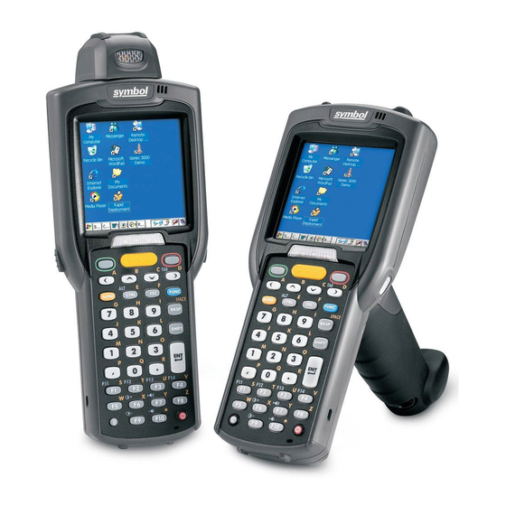
Getting Started 1-5 Parts There are two versions of the MC3000 mobile computers, the MC3000 1D/2D Imager (MC3000-K) and the MC3000 Laser with Rotating Scan Turret (MC3000-R). For more information on the Rotating Scan Turret, see Figure 1-3 on page 1-6. -
Page 24: Rotating Scan Turret
MC3000 Integrator Guide Headset Jack (optional) Scan Window Scan Window Strap/Door Headset Jack Assembly (optional) Screws Stylus Strap/Door Assembly Stylus Holder Latches MC3000-R MC3000-K Figure 1-2. MC3000 Imager (MC3000-K) and MC3000 Laser (MC3000-R) Mobile Computers (back view) Rotating Scan Turret The MC3000-R mobile computer features a Rotating Scan Turret with three position stops. -
Page 25: Mobile Computer Startup
Getting Started 1-7 Mobile Computer Startup To start using the mobile computer: • Install the main battery. • Charge the main battery and the backup battery. • Start the mobile computer. Install Main Battery If the main battery is charged, the mobile computer can be used immediately. If the main battery is not charged, see Battery Charging on page 1-8. -
Page 26: Battery Charging
MC3000 Integrator Guide Battery Charging Use the mobile computer cradles, cables and spare battery chargers to charge the mobile computer main battery. The main battery can be charged before insertion into the mobile computer or after it is installed. There are two main batteries for the MC3000, the Standard Battery and the Extended Life Battery. -
Page 27: Spare Battery Charging
Getting Started 1-9 Table 1-2. Mobile Computer LED Charge Indicators Indication Mobile computer not placed correctly in the cradle; charge cable not connected correctly; charger is not powered. Fast Blinking Amber Error in charging; check placement of the mobile computer. Slow Blinking Amber Mobile computer is charging. -
Page 28: Starting The Mobile Computer
1-10 MC3000 Integrator Guide Starting the Mobile Computer When the mobile computer is powered on for the first time, it initializes. The Symbol Splash screen appears for a short period of time, followed by the Calibration screen. Figure 1-5. Symbol Splash Screen After the calibration procedure is performed the factory settings launch the Series 3000 Demo window. -
Page 29: Series 3000 Demo Window
Getting Started 1-11 Series 3000 Demo Window The Series 3000 Demo window is the factory default menu. On initial power up (or on a warm or cold boot) the Series 3000 Demo window appears. These sample/demo applications are intended to be used by application developers as application development examples. -
Page 30: Main Battery Removal
1-12 MC3000 Integrator Guide Main Battery Removal Before removing the main battery, press the red Power button to turn off the screen. This sets the mobile computer to suspend mode. To remove the main battery: 1. Rotate the latches to the open position. 2. -
Page 31: Strap/Door Assembly Removal And Replacement
Getting Started 1-13 Strap/Door Assembly Removal and Replacement The Strap/Door Assembly consists of a hand strap and the battery door. There are two versions of this assembly, one for the Standard Battery and one for the Extended Life Battery. Before removing the Strap/Door Assembly, press the red Power button to turn off the screen and set the mobile computer to suspend mode. - Page 32 1-14 MC3000 Integrator Guide...
- Page 33 Operating the MC3000 Chapter Contents Introduction ................2-3 Power Button .
- Page 34 MC3000 User Guide Data Capture..................... . . 2-19 Laser Scanning .
-
Page 35: Introduction
Operating the MC3000 2-3 Introduction This chapter provides basic instructions for using the mobile computer and navigating the mobile computer software. Power Button Press the red Power button to toggle the mobile computer between suspend and resume. When the screen is off the mobile computer is in suspend mode and when the screen is on the mobile computer is on. -
Page 36: Power Button
MC3000 User Guide 28-Key Keypad The 28-key keypad contains a Power button, application keys, scroll keys and function keys. The keypad is color-coded to indicate the alternate function key (blue) values and the alternate ALPHA key (orange) values. Note that keypad functions can be changed by an application so the mobile computer keypad may not function as described. - Page 37 Operating the MC3000 2-5 Table 2-2. 28-Key Descriptions Description Power (red) Powers the mobile computer screen on and off (resume and suspend). Green Circle Programmable application function key by default. Red Circle Programmable application function key by default. Scan (yellow) Used in scanning applications, press to scan a bar code.
- Page 38 MC3000 User Guide Table 2-2. 28-Key Descriptions (Continued) Description BKSP BKSP, backspace function by default. SPACE SPACE, space function by default. Shift Press and release the SHIFT key to activate the keypad alternate SHIFT functions. The icon appears on the taskbar. Press and release the SHIFT key again to return to the default keypad functions.
-
Page 39: 38-Key Keypad
Operating the MC3000 2-7 38-Key Keypad The 38-key keypad contains a Power button, application keys, scroll keys and function keys. The keypad is color-coded to indicate the alternate function key (blue) values. Note that keypad functions can be changed by an application so the mobile computer keypad may not function as described. - Page 40 MC3000 User Guide Table 2-3. 38-Key Descriptions Description Power (red) Powers the mobile computer screen on and off (resume and suspend). Green Circle Programmable application function key by default. Red Circle Programmable application function key. Scan (yellow) Used in scanning applications, press to scan a bar code. This key has the same function as activating the side mounted scan buttons.
- Page 41 Operating the MC3000 2-9 Table 2-3. 38-Key Descriptions (Continued) Description Enter Executes a selected item or function. Period/Decimal Point Produces a period for alpha entries and a decimal point for numeric entries. Produces alpha values when the orange ALPHA key is activated. Comma Produces a comma by default.
-
Page 42: 48-Key Keypad
2-10 MC3000 User Guide 48-Key Keypad The 48-key keypad contains a Power button, application keys, scroll keys and function keys. The keypad is color-coded to indicate the alternate function key (blue) values. Note, that keypad functions can be changed by an application so the mobile computer keypad may not function as described. - Page 43 Operating the MC3000 2-11 Table 2-4. 48-Key Descriptions Description Power (red) Powers the mobile computer screen on and off (resume and suspend). Green Circle/ESC Unassigned application function key by default. Red Circle/TAB Unassigned application function key. Scan (yellow) Scan key, used for scanning applications. This key has the same function as pulling the trigger.
- Page 44 2-12 MC3000 User Guide Table 2-4. 48-Key Descriptions (Continued) Description Display Backlight Display backlight. Toggle the display backlight on and off using the display backlight key.
-
Page 45: Series 3000 Demo Window
Operating the MC3000 2-13 Series 3000 Demo Window On initial power up (or on a warm or cold boot) the Series 3000 Demo window appears. This window links to the Test Applications window and the two windows provide the sample/demo applications. The sample/demo applications are intended to be used by application developers as application development examples. -
Page 46: Taskbar
2-14 MC3000 User Guide Taskbar The taskbar (at the bottom of the screen) displays the Start button, active programs, battery status and communication status. The taskbar icons are described in Table 2-5. The taskbar icons display the function status, indicate what programs are active and indicate the battery charge status. -
Page 47: Battery Unknown Icon
Operating the MC3000 2-15 Table 2-5. Taskbar Icons (Continued) Icon Description Indicates that the SHIFT button function is selected. Indicates that the FUNC button function is selected. Indicates that the CTRL button function is selected. Indicates that the ALT character selection is selected. Indicates that the mobile computer is in ALPHA button mode is selected. -
Page 48: Start Button
2-16 MC3000 User Guide Start Button Tap the Start button to launch the Start menu. • Programs: Use to access available programs. • Favorites: Displays files in Favorites directory. • Documents: Displays files in Documents directory. • Settings: Accesses the Control Panel, the Network and Dial-up Connections and the Taskbar and Start menu. •... -
Page 49: Keyboard Input Panel Button
Operating the MC3000 2-17 Keyboard Input Panel Button Use the Keyboard Input Panel as an alternate input device. For more information, see Entering Information Using the Keyboard Input Panel on page 2-19. Desktop Display Button Use the Desktop Display button to minimize all open programs and display the desktop. Windows CE .NET 4.2 Core desktop functions include: •... -
Page 50: Properties
2-18 MC3000 User Guide Properties 1. Select FUNC - CTRL, (to activate the ALT state) and tap on the taskbar to display the Task Manager, Properties window, see Figure 2-9 on page 2-17. 2. Tap Properties to display the Taskbar and Start Menu, General tab. 3. -
Page 51: Entering Information
Operating the MC3000 2-19 Entering Information To enter information: • Use the keypad. • Use the keyboard input panel (soft keyboard) to enter typed text. • Scan bar code data into data fields. ® ® • Use Microsoft ActiveSync to synchronize or copy information from the host computer to the mobile computer. For more information on ActiveSync, refer to the MC3000 Integrator Guide. -
Page 52: Data Capture
2-20 MC3000 User Guide Data Capture The mobile computer has an integrated scanner or imager that is used to collect data by scanning bar codes. Laser Scanning To scan bar codes with the mobile computer: 1. Ensure that the mobile computer is loaded with a scanning application. 2. -
Page 53: Scanning Considerations
Operating the MC3000 2-21 Scanning Considerations Scanning consists of; aim, scan and decode. Scanning performance can be optimized by considering the range and the scanning angle: • Range Any scanning device decodes well over a particular working range — minimum and maximum distances from the bar code. This range varies according to bar code density and scanning device optics. - Page 54 2-22 MC3000 User Guide MC3000-R, Laser Decode Ranges Table 2-7. Ranges Bar Code Density Near 5.0 mil 2.0 in 4.9 in 5.08 cm 12.45 cm 7.5 mil 1.6 in 7.9 in 4.06 cm 20.07 cm 10 mil 1.2 in 10.8 in 3.05 cm 67.95cm UPC A...
-
Page 55: Imaging
Operating the MC3000 2-23 Imaging The imager version of the mobile computer has the following features: • Omnidirectional reading of a variety of bar code symbologies, including the most popular linear, postal, PDF417 and 2-D matrix code types. • The ability to capture and download images to a host for a variety of imaging applications. •... - Page 56 2-24 MC3000 User Guide To scan a symbol using the imager: 1. Center the symbol in any orientation within the aiming pattern. Ensure the entire symbol is within the rectangular area formed by the brackets in the aiming pattern. Linear bar code PDF417 symbol Symbol View Finder...
-
Page 57: Imager Decode Ranges
Operating the MC3000 2-25 Imager Decode Ranges The decode ranges provide the decode distances for barcodes of specified densities. Figure 2-19 shows the imager decode ranges Table 2-8 on page 2-26 lists the scan ranges for the selected bar code densities. The minimum element width (or “symbol density”) is the width in mils of the narrowest element (bar or space) in the symbol. - Page 58 2-26 MC3000 User Guide MC3000-K, Imager Decode Ranges Table 2-8. Ranges Bar Code Density Near 5.0 mil 4.5 in 6.5 in 11.43 cm 16.51cm 7.5 mil 3.3 in 10.7 in 8.38 cm 27.18 cm UPC A 2.5 in 14.2 in 6.35 cm 36.07cm 20 mil...
-
Page 59: Resetting The Mobile Computer
Operating the MC3000 2-27 Resetting the Mobile Computer If the mobile computer stops responding to input, reset it. There are two reset functions, warm boot and cold boot. A warm boot restarts the mobile computer by closing all running programs. All data that is not saved is lost. A cold boot also restarts the mobile computer, but erases all stored records and entries from RAM. -
Page 60: Waking The Mobile Computer
2-28 MC3000 User Guide Waking the Mobile Computer The default wakeup conditions define what actions wakeup the mobile computer. These settings are configurable and the factory default settings shown in Table 2-9 are subject to change/update. Table 2-9. Default Wakeup Conditions Status Description Conditions for Wakeup... -
Page 61: File System Directory Structure
Operating the MC3000 2-29 File System Directory Structure The mobile computer directory structure displays all of the file folders. The pre-installed folders are in flash file system memory and optional removable storage devices (SD storage cards). Figure 2-20. Mobile Computer Directory Structure •... -
Page 62: Connecting To The Internet On A Wireless Network
2-30 MC3000 User Guide Connecting to the Internet on a Wireless Network The mobile computer can connect to the Internet across a wireless network. Before attempting a wireless internet connection, confirm that the Wireless Zero Configuration (WZC) radio is connected to a wireless network. The WZC icon appears in the task bar and indicates the connected/not connected status. - Page 63 Operating the MC3000 2-31 If internet access is not available: 1. Double tap the WZC icon on the task bar. 2. The Wireless Information window displays the connected WLAN, the connection status and the signal strength. Configured wireless networks are listed as preferred. Table 2-11 lists the wireless network connection status icons and the connection status.
- Page 64 2-32 MC3000 User Guide...
- Page 65 Accessories Chapter Contents Introduction ................3-3 Cradles .
- Page 66 MC3000 User Guide...
-
Page 67: Introduction
Accessories 3-3 Introduction The MC3000 accessories provide a variety of product support capabilities. Accessories include cradles, cables, spare battery chargers and SD cards. Cradles • Single Slot Serial/USB cradle charges the mobile computer main battery and/or a spare battery. It also synchronizes the mobile computer with a host computer through either a serial or a USB connection. -
Page 68: Single Slot Serial/Usb Cradle
MC3000 User Guide Single Slot Serial/USB Cradle The Single Slot Serial/USB cradle: • Provides 5.4VDC power for operating the mobile computer, charging the battery and charging a spare battery. • Provides a serial port and a USB port for data communication between the mobile computer and a host computer or other serial devices (e.g., a printer). -
Page 69: Led Charge Indications
Accessories 3-5 To charge the spare battery: 1. Insert the spare battery into the spare battery charging slot, bottom first, and pivot the top of the battery down onto the contact pins. 2. Gently press down on the battery to ensure proper contact. 3. -
Page 70: Four Slot Charge Only Cradle
MC3000 User Guide Four Slot Charge Only Cradle The Four Slot Charge Only cradle: • Provides 5.4VDC power for operating the mobile computer and charging the battery. • Simultaneously charges up to four mobile computers. Battery Charging The Four Slot Charge Only cradle can charge up to four mobile computers simultaneously. To charge the mobile computer: 1. -
Page 71: Four Slot Spare Battery Charger
Accessories 3-7 Four Slot Spare Battery Charger The Four Slot Spare Battery Charger, simultaneously charges up to four spare batteries. Spare Battery Charging To charge up to four MC3000 spare batteries: 1. Insert the spare battery into the spare battery charging slot, bottom first 2. -
Page 72: Cables
MC3000 User Guide Cables This section describes how to setup and use the cables. The cables are available with a variety of connection capabilities. The following MC3000 Communication/Charge cables are available: • Serial (RS232) Charge cable (9-pin D female with power input receptacle) •... -
Page 73: Battery Charging And Operating Power
Accessories 3-9 Battery Charging and Operating Power The MC3000 Communication/Charge cables can charge the mobile computer battery and supply operating power. To charge the mobile computer battery: 1. Connect the MC3000 Communication/Charge cable power input connector to the Symbol approved power source. 2. -
Page 74: Universal Battery Charger (Ubc) Adapter
3-10 MC3000 User Guide Universal Battery Charger (UBC) Adapter The UBC Adapter can be used with a power supply as a standalone spare battery charger or it can be used with the four station UBC2000 to simultaneously charge up to four spare batteries. For additional information on the UBC 2000, refer to the UBC 2000 Quick Reference Guide p/n 70-33188-xx. -
Page 75: Ubc Adapter Led Charge Indications
Accessories 3-11 UBC Adapter LED Charge Indications The UBC Adapter charging LEDs indicate the battery charging status. The Standard Battery usually charges in less than four hours and the Extended Life Battery usually charges in less than six hours. POWER READY or STANDBY or FAULT (Green) (Flashing Yellow) -
Page 76: Secure Device Card
3-12 MC3000 User Guide Secure Device Card The Secure Device (SD) card provides secondary non-volatile storage (the flash memory is slower than RAM). The SD card holder is located under the battery. Follow proper Electro-Static Discharge (ESD) precautions to avoid damaging the SD card. Proper ESD precautions include, but are not limited to, working on an ESD mat and ensuring that the operator is properly grounded. -
Page 77: Plastic Holster
Accessories 3-13 Plastic Holster The Plastic Holster provides a holder for the mobile computer. It consists of a mobile computer holder and a detachable belt clip. Press the release button to remove the detachable belt clip. Release Button Detachable Belt Clip Mobile Computer Holder Figure 3-8. -
Page 78: Using The Plastic Holster
3-14 MC3000 User Guide Using the Plastic Holster Pinch the clip release and attach the Plastic Holster to a belt or waist band. Clip Release Mobile Computer Holder Figure 3-9. Attaching the Plastic Holster... -
Page 79: Inserting And Removing The Mobile Computer
Accessories 3-15 Inserting and Removing the Mobile Computer The Plastic Holster holds the mobile computer on a belt or waist band. To insert the mobile computer, slide the mobile computer into the Plastic Holster with the screen facing the user. To remove the mobile computer, press and lift to remove the mobile computer. - Page 80 3-16 MC3000 User Guide...
- Page 81 Maintenance & Troubleshooting Introduction ................4-3 Maintaining the Mobile Computer.
- Page 82 MC3000 Integrator Guide...
-
Page 83: Introduction
Maintenance & Troubleshooting 4-3 Introduction This chapter includes instructions on cleaning and storing the mobile computer, and provides troubleshooting solutions for potential problems during mobile computer operation. Maintaining the Mobile Computer For trouble-free service, observe the following tips when using the mobile computer: •... -
Page 84: Troubleshooting
MC3000 Integrator Guide Troubleshooting Mobile Computer Table 4-1. Troubleshooting the Mobile Computer Problem Cause Solution Mobile computer does not turn Main battery not charged. Charge or replace the main battery. Main battery not installed Ensure the battery is installed properly. See Install Main Battery on page 1-7. - Page 85 Maintenance & Troubleshooting 4-5 Table 4-1. Troubleshooting the Mobile Computer (Continued) Problem Cause Solution The mobile computer does not Scanning application is not Verify that the mobile computer is loaded with a scanning application. See the system accept scan input. loaded.
-
Page 86: Single Slot Serial/Usb Cradle
MC3000 Integrator Guide Single Slot Serial/USB Cradle Table 4-2. Troubleshooting the Single Slot Serial/USB Cradle Symptom Possible Cause Solution Amber Charge LED Indicator Cradle is not receiving power. Ensure the power cable is connected securely to both the cradle and to AC does not light when mobile power. -
Page 87: Four Slot Charge Only Cradle
Maintenance & Troubleshooting 4-7 Four Slot Charge Only Cradle Table 4-3. Troubleshooting the Four Slot Charge Only Cradle Problem Cause Solution Mobile computer amber Charge LED Cradle is not receiving power. Ensure the power cable is connected securely to both the cradle Indicator does not light when mobile and to AC power. -
Page 88: Ubc Adapter
MC3000 Integrator Guide UBC Adapter Table 4-5. Troubleshooting the UBC Adapter Symptom Possible Cause Solution Battery Charging LED does not Spare battery is not correctly Remove and re-insert the spare battery into the charging slot, ensuring it is correctly light when spare battery is seated. -
Page 89: Appendix A. Technical Specifications
Technical Specifications Appendix Contents Mobile Computer Technical Specifications ........... . A-3... - Page 90 MC3000 Integrator Guide...
-
Page 91: Mobile Computer Technical Specifications
Technical Specifications A-3 Mobile Computer Technical Specifications The following table summarizes the mobile computer technical specifications and intended operating environment. Table A-1. Mobile Computer Technical Specifications Operating Temperature Color 14° to 122°F (-10° to +50°C) Monochrome -4° to 122°F (-20° to +50°C) Storage Temperature -22°... - Page 92 MC3000 Integrator Guide Table A-1. Mobile Computer Technical Specifications (Continued) Data Capture: Code 39, code 128, code 93, codabar, code 11, discrete 2 of 5, EAN-3, EAN-13, 1-D Decode Capability* EAN-128, interleaved 2 of 5, UPCA, UPCE and UPC/EAN supplements. Imaging Decode Capability* Code 39, code 128, code 93, codabar, code 11, discrete 2 of 5, EAN-3, EAN-13, EAN-128, interleaved 2 of 5, TLC39 (telecommunications, UPCA, UPCE, UPC/...
- Page 93 Keypad Functions/Special Characters Appendix Contents Introduction ................B-3 Keypads .
- Page 94 MC3000 User Guide...
- Page 95 Keypad Functions/Special Characters B-3 Introduction This appendix contains the keypad functions/special characters for the 38-Key keypad. Each function/special character is included in the table along with how the function/special character is generated. Keypads The mobile computer is available with one of three keypads: •...
- Page 96 MC3000 User Guide Table B-1. Special Character Generation Map 28-Key Keypad Key Sequence, 38-Key Keypad Key Sequence, 48-Key Keypad Key Sequence, Special Character Special Character Generation Special Character Generation Special Character Generation Use the Keyboard Input Panel* FUNC + 4 Use the Keyboard Input Panel* Use the Keyboard Input Panel* FUNC + 5...
- Page 97 Glossary 802.11/802.11abg A radio protocol that may be used by the Symbol radio card. Access Point Access Point (AP) refers to Symbol’s Ethernet Access Point. It is a piece of communications equipment that manages communications between the host computer system and one or more wireless terminals.
- Page 98 GL-2 MC3000 User Guide ® AirBEAM Smart Client AirBEAM® Smart Client is part of Symbol’s AirBEAM® suite, which also includes AirBEAM® Safe and AirBEAM® Manager. The AirBEAM® Smart Client system uses the network accessible host server to store software files that are to be downloaded to the mobile computers.
- Page 99 Glossary GL-3 Byte On an addressable boundary, eight adjacent binary digits (0 and 1) combined in a pattern to represent a specific character or numeric value. Bits are numbered from the right, 0 through 7, with bit 0 the low-order bit. One byte in memory is used to store one ASCII character.
- Page 100 GL-4 MC3000 User Guide COM port Communication port; ports are identified by number, e.g., COM1, COM2. Continuous Code A bar code or symbol in which all spaces within the symbol are parts of characters. There are no intercharacter gaps in a continuous code.
- Page 101 Glossary GL-5 Flash Memory Flash memory is responsible for storing the system firmware and is non-volatile. If the system power is interrupted the data is not be lost. Gateway Address An IP address for a network gateway or router. A mobile computer may be part of a subnet as specified by its IP address and Netmask.
- Page 102 GL-6 MC3000 User Guide Interleaved 2 of 5 A binary bar code symbology representing character pairs in groups of five bars and five interleaved spaces. Interleaving provides for greater information density. The location of wide elements (bar/spaces) within each group determines which characters are encoded.
- Page 103 Glossary GL-7 Mobile Computer In this text, mobile computer refers to the Symbol Series 9000 wireless portable computer. It can be set up to run as a stand-alone device, or it can be set up to communicate with a network, using wireless radio technology. Nominal The exact (or ideal) intended value for a specified parameter.
- Page 104 GL-8 MC3000 User Guide Scanning Mode The scanner is energized, programmed and ready to read a bar code. Scanning Sequence A method of programming or configuring parameters for a bar code reading system by scanning bar code menus. Software Development Kit Self-Checking Code A symbology that uses a checking algorithm to detect encoding errors within the characters of a bar code symbol.
- Page 105 Glossary GL-9 Symbol Length Length of symbol measured from the beginning of the quiet zone (margin) adjacent to the start character to the end of the quiet zone (margin) adjacent to a stop character. Symbology The structural rules and conventions for representing data within a particular bar code type (e.g.
- Page 106 GL-10 MC3000 User Guide...
- Page 107 Index Numerics ActiveSync ....... . .xiii aiming options 28-key keypad ......2-4 aiming pattern .
- Page 108 IN-2 MC3000 User Guide battery charging ......1-8 backup battery ......1-8 electro-static discharge four slot charge only cradle .
- Page 109 Index IN-3 laser decode ranges ......2-21 radio module specifications ....A-3 laser scanning .
- Page 110 IN-4 MC3000 User Guide strap/door assembly ......1-6 attaching ......1-13 Zebra printer cable .
- Page 111 Tell Us What You Think... We’d like to know what you think about this Manual. Please take a moment to fill out this questionnaire and fax this form to: (631) 738-3318, or mail to: Symbol Technologies, Inc. One Symbol Plaza M/S B-4 Holtsville, NY 11742-1300 Attention: Technical Publications Manager IMPORTANT: If you need product support, please call the appropriate customer support number provided.
- Page 114 Symbol Technologies, Inc. One Symbol Plaza Holtsville, New York 11742-1300 http://www.symbol.com 72-68899-01 Revision A - December 2004...
Need help?
Do you have a question about the MC3090G - Win CE 5.0 Core and is the answer not in the manual?
Questions and answers