Table of Contents
Advertisement
Advertisement
Table of Contents

Related Manuals for Asus MAXIMUS VI IMPACT


Summary of Contents for Asus MAXIMUS VI IMPACT
- Page 1 MAXIMUS VI IMPACT...
- Page 2 Product warranty or service will not be extended if: (1) the product is repaired, modified or altered, unless such repair, modification of alteration is authorized in writing by ASUS; or (2) the serial number of the product is defaced or missing.
-
Page 3: Table Of Contents
Contents Safety information ..................... vii About this guide ....................... viii MAXIMUS VI IMPACT specifications summary ............x Package contents ..................... xiv Installation tools and components ................xv Chapter 1: Product Introduction Special features..................1-1 1.1.1 Product highlights................ 1-1 1.1.2 ROG Gaming Features ............... 1-2 1.1.3... - Page 4 3.6.10 ROG Effects ................3-43 Monitor menu ................... 3-44 Boot menu ....................3-47 Tools menu ....................3-53 3.9.1 ASUS EZ Flash 2 Utility ............3-53 3.9.2 ROG SSD Secure Erase ............3-53 3.9.3 ASUS Overclocking Profile ............3-55 3.9.4 ASUS SPD Information ............. 3-56 3.9.5...
- Page 5 3.11.2 ASUS EZ Flash 2 ..............3-60 3.11.3 ASUS CrashFree BIOS 3 ............3-61 3.11.4 ASUS BIOS Updater ..............3-62 Chapter 4: Software support Installing an operating system ..............4-1 Support DVD information ................4-1 4.2.1 Running the support DVD ............4-1 4.2.2...
- Page 6 Creating a RAID driver disk without entering the OS ....5-7 5.2.2 Creating a RAID driver disk in Windows ........5-8 ® 5.2.3 Installing the RAID driver during Windows OS installation ..5-8 ® Appendices Notices ........................A-1 ASUS contact information ..................A-5...
-
Page 7: Safety Information
Safety information Electrical safety • To prevent electrical shock hazard, disconnect the power cable from the electrical outlet before relocating the system. • When adding or removing devices to or from the system, ensure that the power cables for the devices are unplugged before the signal cables are connected. If possible, disconnect all power cables from the existing system before you add a device. -
Page 8: About This Guide
Refer to the following sources for additional information and for product and software updates. ASUS website The ASUS website (www.asus.com) provides updated information on ASUS hardware and software products. Optional documentation Your product package may include optional documentation, such as warranty flyers, that may have been added by your dealer. -
Page 9: Conventions Used In This Guide
Conventions used in this guide To ensure that you perform certain tasks properly, take note of the following symbols used throughout this manual. DANGER/WARNING: Information to prevent injury to yourself when trying to complete a task. CAUTION: Information to prevent damage to the components when trying to complete a task IMPORTANT: Instructions that you MUST follow to complete a task. -
Page 10: Maximus Vi Impact Specifications Summary
Turbo Boost Technology 2.0* ® * The Intel Turbo Boost Technology 2.0 support depends on the CPU ® types. ** Refer to www.asus.com for Intel CPU support list Chipset Intel Z87 Express Chipset ® Dual channel memory architecture 2 x DIMM, max. 16GB, DDR3 3000 (O.C.) / 2933 (O.C.) / 2800 (O.C.) / 2666 (O.C.) / 2600 (O.C.) / 2400 (O.C.) / 2200 (O.C.) / 2133... - Page 11 6 x USB 3.0 ports (4 ports at back panel [blue], 2 ports at mid-board [red]*) 6 x USB 2.0 ports (4 ports at back panel, 1 for ROG Connect; 2 ports at mid-board**) * Supports ASUS USB 3.0 Boost. UASP standard on the Intel native ® USB 3.0 is only supported under Windows ®...
- Page 12 - ASUS CrashFree BIOS 3 - ASUS EZ Flash 2 - ASUS C.P.R. (CPU Parameter Recall) ASUS Q-Design - ASUS Q-Code - ASUS Q-Shield - ASUS Q-Cable - ASUS Q-LED (CPU, DRAM, VGA, Boot Device LED) - ASUS Q-DIMM (continued on the next page)
- Page 13 MAXIMUS VI IMPACT specifications summary 1 x USB 3.0 connector (supports additional 2 USB 3.0 ports) 1 x USB 2.0 connector (supports additional 2 USB 2.0 port sharing with ROG_EXT header) 1 x ROG Extension (ROG_EXT) header 4 x SATA 6Gb/s connectors...
-
Page 14: Package Contents
Package contents Check your motherboard package for the following items. Motherboard ROG MAXIMUS VI IMPACT Cables 4 x SATA 6 Gb/s cables Accessories I/O Shield 1 x 12-in-1 ROG cable label 1 x Q-Cable 1 x Optional 4-in-1 washers for CPU cooler backplate... -
Page 15: Installation Tools And Components
Installation tools and components 1 bag of screws Philips (cross) screwdriver PC chassis Power supply unit Intel LGA 1150 CPU Intel LGA 1150 compatible CPU Fan DDR3 DIMM SATA hard disk drive SATA optical disc drive (optional) Graphics card (optional) The tools and components in the table above are not included in the motherboard package. -
Page 17: Chapter 1: Product Introduction
3.0 (PCIe 3.0) is the PCI Express bus standard that provides twice the ® performance and speed of PCIe 2.0. It provides an optimal graphics performance, unprecedented data speed and seamless transition with its complete backward compatibility to PCIe 1.0/2.0 devices. ASUS MAXIMUS VI IMPACT... -
Page 18: Rog Gaming Features
GameFirst II ASUS GameFirst II, with cFOS Traffic Shaping technology, provides a powerful and user- friendly network control to easily frag your gaming system. Featuring the EZ Mode for beginners’ setup and Advanced Mode for professionals’ tweaking, your frags comes first. -
Page 19: Asus Special Features
ASUS Special Features AI Suite 3 With its user-friendly interface, ASUS AI Suite 3 consolidates all the exclusive ASUS features into one simple-to-use software package. It allows you to supervise fan speed control, voltage and sensor readings. This all-in-one software offers diverse and ease to use functions, with no need to switch back and forth between different utilities. -
Page 20: Dts Connect
MemTweakIt MemTweakIt is a DRAM efficiency tool that allows you to read DRAM timings and allows you to post and share your DRAM configuration scores to the ROG website. DTS Connect To get the most out of your audio entertainment across all formats and quality levels, DTS Connect combines two enabling technologies, DTS Neo:PC™... -
Page 21: Motherboard Overview
Before you install or remove any component, ensure that the ATX power supply is switched off or the power cord is detached from the power supply. Failure to do so may cause severe damage to the motherboard, peripherals, or components. ASUS MAXIMUS VI IMPACT... -
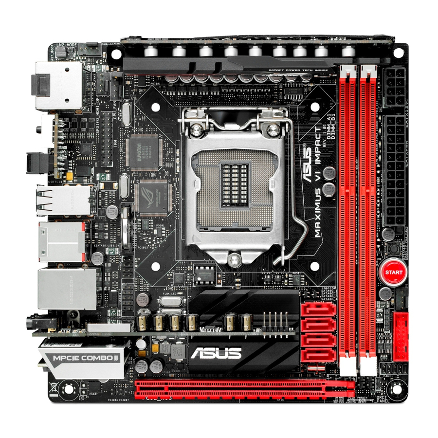
Page 22: Motherboard Layout
1.2.2 Motherboard layout Refer to 1.2.9 Internal connectors and 2.3.1 Rear I/O connection for more information about rear panel connectors and internal connectors. Chapter 1: Product introduction... -
Page 23: Layout Contents
1-39 15. USB 2.0 connectors (10-1 pin USB1314) 1-33 16. ROG Extension connector (8 pin ROG_EXT) 1-37 17. Fast Boot jumper (3-pin FAST_BOOT) 1-21 18. MemOK! button 1-19 19. DirectKey button 1-20 20. Q_Code LEDs 1-24 ASUS MAXIMUS VI IMPACT... -
Page 24: Central Processing Unit (Cpu)
Contact your retailer immediately if the PnP cap is missing, or if you see any damage to the PnP cap/socket contacts/motherboard components. ASUS will shoulder the cost of repair only if the damage is shipment/ transit-related. -
Page 25: System Memory
The motherboard comes with two Double Data Rate 3 (DDR3) Dual Inline Memory Modules (DIMM) slots. A DDR3 module is notched differently from a DDR or DDR2 module. DO NOT install a DDR or DDR2 memory module to the DDR3 slot. Recommended memory configurations ASUS MAXIMUS VI IMPACT... -
Page 26: Memory Configurations
Memory configurations You may install 1GB, 2GB, 4GB and 8GB unbuffered and non-ECC DDR3 DIMMs into the DIMM sockets. • Memory module with memory frequency higher than 2133 MHz and its corresponding timing or the loaded XMP profile is not the JEDEC memory standard. The stability and compatibility of these memory modules depend on the CPU’s capabilities and other installed devices. - Page 27 MAXIMUS VI IMPACT Motherboard Qualified Vendors List (QVL) DDR3 3000 MHz capacity Vendors Part No. Size Chip Chip Timing Voltage DIMM socket support Brand (Optional) G.SKILL F3-3000C12Q-16GTXDG 16GB (4x4GB) 12-14-14-35 1.65V • DDR3 2933 MHz capacity Vendors Part No. Size...
- Page 28 DDR3 2400 MHz capacity Vendors Part No. Size Chip Chip Timing Voltage DIMM Brand socket support (Optional) A-DATA AX3U2400GC4G10(XMP) 10-12-12-31 1.65 • A-DATA AX3U2400GW8G11(XMP) 16GB (2x8GB) 11-13-13-35 1.65 • Apacer 783BAGF3.AFD0C(XMP) 8GB ( 2x 4GB ) 11-11-11-30 • CORSAIR CMD16GX3M2A2400C10 16GB (2x8GB) 10-12-12-31 1.65...
- Page 29 1.65 • (XMP) Asint SLA302G08-ML2HB (XMP) Hynix H5TQ2G83B 9-9-9-27 • FRH9C GEIL GUP34GB2000C9DC (XMP) 4GB (2x2GB) 9-9-9-28 1.65 • Patriot PV736G2000ELK (XMP) 6GB (3x2GB) 7-7-7-20 1.65 • Patriot PX7312G2000ELK (XMP) 12GB (3x4GB) 9-11-9-27 1.65 • ASUS MAXIMUS VI IMPACT 1-13...
- Page 30 DDR3 2000 MHz capacity Vendors Part No. Size Chip Chip NO. Timing Voltage DIMM socket Brand support (Optional) AEXEA AXA3ES4GK2000LG28V(XMP) 4GB (2x2GB) 1.65 • Asint SLA302G08-ML2HB(XMP) Hynix H5TQ2G 9-9-9-27 • 83BFRH9C GEIL GUP34GB2000C9DC(XMP) 4GB (2x2GB) 9-9-9-28 1.65 • Patriot PV736G2000ELK(XMP) 6GB (3x2GB) 7-7-7-20 1.65...
- Page 31 ASUS exclusively provides hyper DIMM support function. • Hyper DIMM support is subject to the physical characteristics of individual CPUs. Load the X.M.P. settings in the BIOS for the hyper DIMM support. • Visit the ASUS website for the latest QVL. ASUS MAXIMUS VI IMPACT 1-15...
-
Page 32: Expansion Slot
1.2.5 Expansion slot Unplug the power cord before adding or removing expansion card. Failure to do so may cause you physical injury and damage motherboard components. Slot No. Slot Description PCIe 3.0/2.0 x16 slot Chapter 1: Product introduction 1-16... - Page 33 – EHCI# 0 (USB 2.0) – – – – – – shared EHCI# 1 (USB 2.0) – – – – shared – – – XHCI (USB 3.0) – – – – – shared – – ASUS MAXIMUS VI IMPACT 1-17...
-
Page 34: Onboard Buttons
1.2.6 Onboard buttons Onboard buttons allow you to fine-tune performance when working on a bare or open- case system. This is ideal for overclockers and gamers who continually change settings to enhance system performance. Power-on button The motherboard comes with a power-on button that allows you to power up or wake up the system. - Page 35 BIOS has been restored to its default settings. • We recommend that you download and update to the latest BIOS version from the ASUS website at www.asus.com after using the MemOK! function. ASUS MAXIMUS VI IMPACT 1-19...
- Page 36 DirectKey button This feature allows your system to go to the BIOS Setup program with the press of a button. With DirectKey, you can enter the BIOS anytime without having to press the <Del> key during POST. It also allows you to turn on or turn off your system and conveniently enter the BIOS during boot-up.
-
Page 37: Jumper
POST. It allows the processor to run at an extremely low temperature and helps the system boot fast. Fast Boot jumper (3-pin FAST_BOOT) This jumper allows you to enable or disable fast boot feature. When enabled, the system boot speed is accelerated. ASUS MAXIMUS VI IMPACT 1-21... -
Page 38: Onboard Leds
1.2.8 Onboard LEDs Hard Disk LED The hard disk LED is designed to indicate the hard disk activity. It blinks when data is being written into or read from the hard disk drive. The LED does not light up when there is no hard disk drive connected to the motherboard or when the hard disk drive does not function. - Page 39 LED continues flashing until the problem is solved. This user-friendly design provides an intuitive way to locate the root problem within seconds. BIOS Flashback LED This LED flashes when the BIOS is updating and turns off after the BIOS update. ASUS MAXIMUS VI IMPACT 1-23...
- Page 40 Q-Code LEDs The Q-Code LED design provides you with a 2-digit error code that displays the system status. Refer to the Q-Code table on the next page for details. • The Q-Code LED automatically displays the POST code upon boot and the CPU temperature upon entering the operating system.
- Page 41 Reserved for ASL (see ASL Status Codes section below) Memory Installed 32 – 36 CPU post-memory initialization 37 – 3A Post-Memory System Agent initialization is started 3B – 3E Post-Memory PCH initialization is started DXE IPL is started (continued on the next page) ASUS MAXIMUS VI IMPACT 1-25...
- Page 42 Q-Code table Code Description Memory initialization error. Invalid memory type or incompatible memory 50 – 53 speed Unspecified memory initialization error Memory not installed Invalid CPU type or Speed CPU mismatch CPU self test failed or possible CPU cache error CPU micro-code is not found or micro-code update is failed Not used Power on.
- Page 43 Recovery condition triggered by user (Forced recovery) Recovery process started Recovery firmware image is found Recovery firmware image is loaded F5 – F7 Reserved for future AMI progress codes Recovery PPI is not available (continued on the next page) ASUS MAXIMUS VI IMPACT 1-27...
- Page 44 Q-Code table Code Description Recovery capsule is not found Invalid recovery capsule FB – FF Reserved for future AMI error codes DXE Core is started NVRAM initialization Installation of the PCH Runtime Services 63 – 67 CPU DXE initialization is started PCI host bridge initialization System Agent DXE initialization is started System Agent DXE SMM initialization is started...
- Page 45 USB hot plug PCI bus hot plug Clean-up of NVRAM Configuration Reset (reset of NVRAM settings) B8– BF Reserved for future AMI codes CPU initialization error System Agent initialization error (continued on the next page) ASUS MAXIMUS VI IMPACT 1-29...
- Page 46 Q-Code table Code Description PCH initialization error Some of the Architectural Protocols are not available PCI resource allocation error. Out of Resources No Space for Legacy Option ROM No Console Output Devices are found No Console Input Devices are found Invalid password Error loading Boot Option (LoadImage returned error) Boot Option is failed (StartImage returned error)
-
Page 47: Internal Connectors
ATA RAID set using these connectors, set the SATA Mode item in the BIOS to [RAID Mode]. Refer to section 3.6.3 SATA Configuration for details. When using NCQ, set the SATA Mode in the BIOS to [AHCI Mode]. Refer to section • 3.6.3 SATA Configuration for details. ASUS MAXIMUS VI IMPACT 1-31... - Page 48 USB 3.0 connector (20-1 pin USB3_12) This connector allows you to connect a USB 3.0 module for additional USB 3.0 front or rear panel ports. With an installed USB 3.0 module, you can enjoy all the benefits of USB 3.0 including faster data transfer speeds of up to 5Gbps, faster charging time for USB-chargeable devices, optimized power efficiency, and backward compatibility with USB 2.0.
- Page 49 These USB connectors comply with USB 2.0 specification that supports up to 480 MBps connection speed. Never connect a 1394 cable to the USB connectors. Doing so will damage the motherboard! The USB2.0 ports (USB1314) at mid-board share with ROG extension (ROG_EXT) port. ASUS MAXIMUS VI IMPACT 1-33...
- Page 50 CPU and chassis fan connectors (4-pin CPU_FAN; 4-pin CHA_FAN1-3) Connect the fan cables to the fan connectors on the motherboard, ensuring that the black wire of each cable matches the ground pin of the connector. • DO NOT forget to connect the fan cables to the fan connectors. Insufficient air flow inside the system may damage the motherboard components.
- Page 51 1000W power or above to ensure the system stability. • If you are uncertain about the minimum power supply requirement for your system, refer to the Recommended Power Supply Wattage Calculator at http://support.asus. com/PowerSupplyCalculator/PSCalculator.aspx?SLanguage=en-us for details. ASUS MAXIMUS VI IMPACT...
- Page 52 Front panel and speaker connectors (10-1 pin PANEL; 4 pin SPEAKER) These connectors support several chassis-mounted functions. • System power LED (2-pin PLED) This 2-pin connector is for the system power LED. Connect the chassis power LED cable to this connector. The system power LED lights up when you turn on the system power, and blinks when the system is in sleep mode.
- Page 53 This connector is for the OC Panel and other ROG devices. • The OC Panel is purchased separately. • The OC Panel allows you to perform overclocking without going to the BIOS setup, loading the OS, or using overclocking software and utilities. ASUS MAXIMUS VI IMPACT 1-37...
- Page 54 TPM connector (20-1 pin TPM) This connector supports a Trusted Platform Module (TPM) system, which securely store keys, digital certificates, passwords and data. A TPM system also helps enhance the network security, protects digital identities, and ensures platform integrity. mPCIe Combo II connector (36-2 pin MPCIE_COMBO_II) This connector is for the bundled mPCIE Combo II card that offers expandability and connectivity solutions for an optimal system performance.
- Page 55 It also has the front panel audio connector for a chassis-mounted front panel audio I/O module. Connect your bundled SupremeFX Impact audio card to this connector. Refer to section 1.2.11 SupremeFX Impact audio card for more details. ASUS MAXIMUS VI IMPACT 1-39...
-
Page 56: Probeit
1.2.10 ProbeIt The ROG ProbeIt allows you to detect your system’s current voltage and OC settings. Use a multimeter to measure the ProbeIt points even during overclocking. Using ProbeIt You can connect the multimeter to Probelt points on your motherboard as shown on the illustration below. -
Page 57: Supremefx Impact Audio Card
Front Panel Type item in the BIOS setup to [HD Audio] or [AC97]. Refer to section 3.6.7 Onboard Devices Configuration for more details. • To use the Music PnP feature, refer to section 2.3.1 Rear I/O connection. ASUS MAXIMUS VI IMPACT 1-41... - Page 58 Audio ports These high-definition audio ports allow you to connect your audio devices such as high-definition speakers, microphone, or a headset for a superior audio experience. Line-in port Line-out port Microphone port To know more about channel configurations and connecting audio devices, refer to section 2.3 Motherboard rear and audio connections.
-
Page 59: Chapter 2: Basic Installation
The diagrams in this section are for reference only. The motherboard layout may vary with models. Install the ASUS Q-Shield to the chassis rear I/O panel. Remove the two screws and nuts on both sides of the Impact Power card from the motherboard using a screw driver and set them aside for future use. - Page 60 Place the motherboard into the chassis, ensuring that its rear I/O ports are aligned to the chassis’ rear I/O panel. Place four screws into the holes indicated by circles to secure the motherboard to the chassis. Chapter 2: Basic Installation...
- Page 61 DO NOT overtighten the screws! Doing so can damage the motherboard. ASUS MAXIMUS VI IMPACT...
-
Page 62: Cpu Installation
2.1.2 CPU installation Ensure that you install the correct CPU designed for LGA1150 socket only. DO NOT install a CPU designed for LGA155 and LGA1156 sockets on the LGA1150 socket. Chapter 2: Basic Installation... -
Page 63: Supremefx Impact Audio Card Installation
2.1.3 SupremeFX Impact audio card installation ASUS MAXIMUS VI IMPACT... -
Page 64: Dimm Installation
2.1.4 DIMM installation To remove a DIMM Chapter 2: Basic Installation... -
Page 65: Cpu Heatsink And Fan Assembly Installation
2.1.5 CPU heatsink and fan assembly installation Apply the Thermal Interface Material to the CPU heatsink and CPU before you install the heatsink and fan, if necessary. To install the CPU heatsink and fan assembly ASUS MAXIMUS VI IMPACT... - Page 66 If you have difficulty in installing a CPU fan with a cooler backplate of varying design, we suggest to use the bundled plastic washers to give space between the motherboard and the backplate. Peel of the adhesive’s cover and attach them to the screw holes at the back of the motherboard, as shown.
- Page 67 To uninstall the CPU heatsink and fan assembly ASUS MAXIMUS VI IMPACT...
-
Page 68: Atx Power Connection
2.1.6 ATX Power connection Chapter 2: Basic Installation 2-10... -
Page 69: Sata Device Connection
2.1.7 SATA device connection ASUS MAXIMUS VI IMPACT 2-11... -
Page 70: Front I/O Connector
2.1.8 Front I/O Connector To install USB 2.0 connector To install front panel audio connector F_PANEL USB 2.0 To install USB 3.0 connector USB 3.0 Chapter 2: Basic Installation 2-12... -
Page 71: Expansion Card Installation
2.1.9 Expansion Card installation To install PCIe x16 cards ASUS MAXIMUS VI IMPACT 2-13... -
Page 72: Mpcie Combo Ii Card Installation
2.1.10 mPCIe Combo II card installation ROG mPCIe Combo II card offers expandability solutions with the latest connectivity standards via the proprietary connector onboard. It provides mini PCI Express 2.0 plus USB 2.0 which is bundled with Wi-Fi and Bluetooth module and features the M.2 (NGFF) slot for installing an SSD card. - Page 73 2. Installing the mPCIe Combo II card To install the mPCIe Combo II card to your motherboard: Remove the black screw near the 36-2 pin connector. ASUS MAXIMUS VI IMPACT 2-15...
- Page 74 Locate the MPCIE_COMBO_II connector on the motherboard then align and insert the mPCIe Combo II card to the MPCIE_COMBO_II connector. The mPCIe Combo II fits in one orientation only. Insert the mPCIe Combo II carefully to prevent damage to the card, connector pins, or to the motherboard.
- Page 75 Insert the connector into the I/O shield’s Wi-Fi port hole. Replace the bolt on the connector to secure the antenna connector and the I/O shield in place. ASUS MAXIMUS VI IMPACT 2-17...
- Page 76 Secure the Wi-Fi antenna cable to the hooks on the I/O shield, as shown. Chapter 2: Basic Installation 2-18...
-
Page 77: Bios Update Utility
For more BIOS update utilities in BIOS setup, refer to the section Updating BIOS in Chapter 3. Updating BIOS may have risks. If the BIOS program is damaged during the process and results to the system’s failure to boot up, please contact your local ASUS Service Center. ASUS MAXIMUS VI IMPACT 2-19... -
Page 78: Motherboard Rear And Audio Connections
Motherboard rear and audio connections 2.3.1 Rear I/O connection Rear panel connectors 1. Optical S/PDIF OUT port 2. Clear CMOS button 3. eSATA port 4. LAN (RJ-45) port* 5. HDMI port 6. DisplayPort 7. ROG Connect button 8. USB 2.0 ports 7-10 9. - Page 79 Jack-retasking supports 4.1, 5.1, and 7.1-channel audio outputs. Launch Realtek HD Audio Manager to configure the jack-retasking setting. • To support 7.1 channel audio output, ensure that your chassis has an HD audio module on the front panel. ASUS MAXIMUS VI IMPACT 2-21...
-
Page 80: Audio I/O Connections
2.3.2 Audio I/O connections Audio I/O ports Connect to Headphone and Mic Connect to Stereo Speakers Chapter 2: Basic Installation 2-22... - Page 81 Connect to 2.1 channel Speakers Connect to 4.1 channel Speakers Connect to 5.1 channel Speakers ASUS MAXIMUS VI IMPACT 2-23...
- Page 82 Connect to 7.1 channel Speakers Using the Music PnP Music PnP, an exclusive feature in your motherboard, allows you to listen to music files when your system is turned off. Ensure that your system is connected to a grounded power outlet. Chapter 2: Basic Installation 2-24...
-
Page 83: Starting Up For The First Time
While the system is ON, press the power button for less than four seconds to put the system on sleep mode or soft-off mode, depending on the BIOS setting. Press the power switch for more than four seconds to let the system enter the soft-off mode regardless of the BIOS setting. ASUS MAXIMUS VI IMPACT 2-25... - Page 84 Chapter 2: Basic Installation 2-26...
-
Page 85: Chapter 3: Bios Setup
BIOS setup Knowing BIOS The new ASUS UEFI BIOS is a Unified Extensible Interface that complies with UEFI architecture, offering a user-friendly interface that goes beyond the traditional keyboard- only BIOS controls to enable a more flexible and convenient mouse input. You can easily navigate the new UEFI BIOS with the same smoothness as your operating system. -
Page 86: Bios Setup Program
BIOS setup program Use the BIOS Setup to update the BIOS or configure its parameters. The BIOS screen include navigation keys and brief onscreen help to guide you in using the BIOS Setup program. Entering BIOS at startup To enter BIOS Setup at startup, press <Delete> during the Power-On Self Test (POST). If you do not press <Delete>, POST continues with its routines. -
Page 87: Ez Mode
Power Saving mode • The boot device options vary depending on the devices you installed to the system. The Boot Menu (F8) button is available only when the boot device is installed to the • system. ASUS MAXIMUS VI IMPACT... -
Page 88: Advanced Mode
3.2.2 Advanced Mode The Advanced Mode provides advanced options for experienced end-users to configure the BIOS settings. The figure below shows an example of the Advanced Mode. Refer to the following sections for the detailed configurations. To access the Advanced Mode, click Exit, then select Advanced Mode or press F7 hotkey. Menu items Menu bar General help... -
Page 89: Menu Items
This button allows you to enter notes of the activities that you have done in BIOS. • The Quick Note function does not support the following keyboard functions: delete, cut, copy and paste. • You can only use the alphanumeric characters to enter your notes. ASUS MAXIMUS VI IMPACT... -
Page 90: My Favorites
Last Modified button This button shows the items that you last modified and saved in BIOS Setup. My Favorites MyFavorites is your personal space where you can easily save and access your favorite BIOS items. Adding items to My Favorites To add frequently-used BIOS items to My Favorites: Use the arrow keys to select an item that you want to add. -
Page 91: Extreme Tweaker Menu
Allows you to load the various settings suitable for your overclocking needs. Load Gamer’s OC Profile Allows you to load the overclocking presets suited for gaming. Configuration options: [Yes] [No] Load 190 BCLK Profile Allows you to load the 190 Base Clock profile. Configuration options: [Yes] [No] ASUS MAXIMUS VI IMPACT... - Page 92 Load 195 BCLK Profile Allows you to load the 195 Base Clock profile. Configuration options: [Yes] [No] Load 200 BCLK Profile Allows you to load the 200 Base Clock profile. Configuration options: [Yes] [No] Ai Overclock Tuner [Auto] Allows you to select the CPU overclocking options to achieve the desired CPU internal frequency.
- Page 93 Max. CPU Cache Ratio [Auto] Allows you to set the maximum possible ratio on the Uncore part of the processor. Use the <+> or <-> keys to adjust the value. The values depend on the CPU installed. ASUS MAXIMUS VI IMPACT...
- Page 94 Internal PLL Overvoltage [Auto] Allows you to enable the internal PLL voltage for K-SKU CPUs to get the extreme overclocking capability. Configuration options: [Auto] [Enabled] [Disabled] BCLK Frequency: DRAM Frequency Ratio [Auto] Allows you to set the base clock frequency of the DRAM frequency ratio. [Auto] The DRAM ratio is set to its optimized settings.
- Page 95 Load 2x8GB Samsung 1.65V 2400 Configuration options: [Yes] [No] Load 2x8GB Samsung 1.80V 2933 Configuration options: [Yes] [No] Load 2x8GB Hynix 1.85V 2600 Configuration options: [Yes] [No] Load 2x8GB New Hynix 1.85V 2600 Configuration options: [Yes] [No] ASUS MAXIMUS VI IMPACT 3-11...
- Page 96 Load 2GB RAW MHz Configuration options: [Yes] [No] Load 4GB/8GB RAW MHz Configuration options: [Yes] [No] Maximus Tweak [Auto] [Auto] Allows the system to set the memory compatibility, overclocking, and system performance. [Mode 1] Helps memory compatibility in your system. [Mode 2] Helps overclocking and stabilizes system performance.
- Page 97 Configuration options: [Auto] [1] - [15] DRAM IO-L (CHA_R0D1) [Auto] Configuration options: [Auto] [1] - [15] DRAM IO-L (CHA_R1D0 [Auto] Configuration options: [Auto] [1] - [15] DRAM IO-L (CHA_R1D1 [Auto] Configuration options: [Auto] [1] - [15] ASUS MAXIMUS VI IMPACT 3-13...
- Page 98 DRAM IO-L (CHB_R0D0 [Auto] Configuration options: [Auto] [1] - [15] DRAM IO-L (CHB_R0D1) [Auto] Configuration options: [Auto] [1] - [15] DRAM IO-L (CHB_R1D0) [Auto] Configuration options: [Auto] [1] - [15] DRAM IO-L (CHB_R1D1) [Auto] Configuration options: [Auto] [1] - [15] Third Timings tRDRD [Auto] Configuration options: [Auto] [1] –...
- Page 99 Configuration options: [Enable Both DIMMS] [Disable DIMM0] [Disable DIMM1] [Disable Both DIMMS] Scrambler Setting [Optimized ...] Set this item to [Optimized (ASUS)] to enhance system stability. Configuration options: [Optimized (ASUS)] [Default (MRC)] MCH Full Check [Auto] Set this item to [Enabled] to enhance the system stability. Set to [Disabled] to enhance the DRAM overclocking capability.
- Page 100 DQS Sense Amplifier [Auto] Reducing the value helps in overclocking and over-voltage. Configuration options: [Auto] [+8] – [-6] CMD Sense Amplifier [Auto] Reducing the value helps in overclocking and over-voltage. Configuration options: [Auto] [+8] – [-6] DRAM Swizzling Bit 0 [Auto] Set these items to [Enabled] to enhance overclocking capability.
- Page 101 Set the phase control on its default setting. [Standard] Set the phase control based on the CPU command. [Optimized] Set the ASUS optimized phase tuning profile. [Extreme] Set the full phase mode [Manual Set manually to a faster phase response to increase system...
- Page 102 The following item appears only when you set the CPU Power Phase Control to [Manual Adjustment]. Manual Adjustment [Fast] Allows you to set a response for the CPU power phase control. Configuration options: [Ultra Fast] [Fast] [Medium] [Regular] CPU Power Duty Control [T.Probe] CPU Power Duty Control adjusts the current of every VRM phase and the thermal conditions of every phase component.
- Page 103 The values range from 0.00V to 3.00V at 0.00625V increment. Eventual PLL Termination Voltage [Auto] Set an eventual phase-locked loop termination voltage. Use the <+> or <-> key to adjust the value. The values range from 0.00V to 3.00V at 0.00625V increment. ASUS MAXIMUS VI IMPACT 3-19...
- Page 104 ICC Ringback Canceller [Auto] Set this item to [Enabled] to control the noise level at the Integrated Clock Controller. [Enable] Allows a better High DMI Frequency O.C. [Disable] Allows a better Low DMI Frequency O.C. Clock Crossing VBoot [Auto] Allows you to increase the value of the clock crossing voltage boot when the rising edge of BCLK DN is equal to the falling edge of the BCLK DP.
-
Page 105: Cpu Power Management
0% to 6%. CPU Internal Power Fault Control Thermal Feedback [Auto] Allows the CPU to take precautionary actions when the thermal conditions of the external regulator exceeds the threshold. Configuration options: [Auto] [Disabled] [Enabled] ASUS MAXIMUS VI IMPACT 3-21... - Page 106 CPU Integrated VR Fault Management [Auto] Allows you to prevent tripping the Fully Integrated Voltage Regulator when doing over-voltage. Configuration options: [Auto] [Disabled] [Enabled] We recommend to set this item to [Disabled] when overclocking. CPU Internal Power Configuration CPU Integrated VR Efficiency Management [Auto] Allows you to improve power saving when the processor is in low power state.
- Page 107 Allows you to set the amount of voltage fed to the analog portion of the input/output of the processor. Increase when increasing DRAM frequency. Use the <+> or <-> key to adjust the value. The values range from 1.000000V to 2.200000V at 0.003125V increment. ASUS MAXIMUS VI IMPACT 3-23...
- Page 108 CPU Digital I/O Voltage [Auto] Allows you to set the amount of voltage fed to the analog portion of the input/output of the processor. Increase when increasing DRAM frequency. Use the <+> or <-> key to adjust the value. The values range from 1.000000V to 2.200000V at 0.003125V increment.
- Page 109 Allows you to set the amount of voltage fed to the system agent of the processor including its PCIE controller and power control unit (PCU). Increase when increasing DRAM frequency. Use the <+> or <-> key to adjust the value. The values range from 0.001V to 0.999V at 0.001V increment. ASUS MAXIMUS VI IMPACT 3-25...
- Page 110 CPU Analog I/O Voltage Offset Mode Sign [+] To offset the voltage by a positive value. To offset the voltage by a negative value. CPU Analog I/O Voltage Offset [Auto] Allows you to set the amount of voltage fed for the analog portion of the input/output on the processor.
- Page 111 CPU Spread Spectrum [Auto] [Auto] Default configuration [Disabled] Enhances the BCLK (base clock) overclocking ability. BCLK Recovery [Enabled] Allows you to enable or disable the BCLK (base clock) recovery feature. Configuration options: [Enabled] [Disabled] [Ignore] ASUS MAXIMUS VI IMPACT 3-27...
-
Page 112: Main Menu
Main menu The Main menu screen appears when you enter the Advanced Mode of the BIOS Setup program. The Main menu provides you an overview of the basic system information, and allows you to set the system date, time, language, and security settings. Security The Security menu items allow you to change the system security settings. -
Page 113: Administrator Password
Installed. To set a user password: Select the User Password item and press <Enter>. From the Create New Password box, key in a password, then press <Enter>. Confirm the password when prompted. ASUS MAXIMUS VI IMPACT 3-29... -
Page 114: Advanced Menu
To change a user password: Select the User Password item and press <Enter>. From the Enter Current Password box, key in the current password, then press <Enter>. From the Create New Password box, key in a new password, then press <Enter>. Confirm the password when prompted. -
Page 115: Cpu Configuration
Allows you to choose the number of CPU cores to activate in each processor package. Configuration options: [All] [1] [2] [3] Limit CPUID Maximum [Disabled] [Enabled] Allows legacy operating systems to boot even without support for CPUs with extended CPUID functions. [Disabled] Disables this function. ASUS MAXIMUS VI IMPACT 3-31... - Page 116 Execute Disable Bit [Enabled] [Enabled] Enables the No-Execution Page Protection Technology. [Disabled] Forces the XD feature flag to always return to zero (0). Intel Virtualization Technology [Disabled] ® [Enabled] Allows a hardware platform to run multiple operating systems separately and simultaneously, enabling one system to virtually function as several systems.
-
Page 117: Pch Configuration
Allows you to configure the PCI Express slots. DMI Link ASPM Control [Auto] Allows you to control the ASPM (Active State Power Management) on both Northbridge side and Southbridge side of the DMI Link. Configuration options: []Auto] [Disabled] [Enabled] ASUS MAXIMUS VI IMPACT 3-33... -
Page 118: Intel Smart Connect Technology
ASPM Support [Disabled] Allows you to set the ASPM level. Configuration options: [Disabled] [Auto] [L0s] [L1] [L0sL1] PCIe Speed [Auto] Allows you to select the PCI Express port speed. Configuration options: [Auto] [Gen1] [Gen2] Intel (R) Rapid Start Technology [Disabled] Allows you to enable or disable Intel Rapid Start Technology. -
Page 119: Sata Configuration
Set to [RAID] when you want to create a RAID configuration from the SATA hard disk drives. Aggressive LPM Support [Auto] Allows you to enable the PCH to aggressively enter link power state. Configuration options: [Auto] [Disabled] [Enabled] ASUS MAXIMUS VI IMPACT 3-35... -
Page 120: System Agent Configuration
S.M.A.R.T. Status Check [Enabled] S.M.A.R.T. (Self-Monitoring, Analysis and Reporting Technology) is a monitor system. When read/write of your hard disk errors occur, this feature allows the hard disk to report warning messages during the POST. Configuration options: [Enabled] [Disabled] Hot Plug [Disabled] (SATA6G_1 - SATA6G_4 [Red]; SATA6G [NGFF]; SATA6G [Red]) These items appear only when you set the SATA Mode Selection item to [AHCI] or [RAID], and allow you to enable/disable SATA Hot Plug Support. -
Page 121: Memory Configuration
Allows you to configure the memory configuration parameters. Memory Scrambler [Enabled] Allows you to enable or disable the Memory Scrambler support. Configuration options: [Enabled] [Disabled] Memory Remap [Enabled] Allows you to enable remapping the memory above 4GB. Configuration options: [Enabled] [Disabled] ASUS MAXIMUS VI IMPACT 3-37... -
Page 122: Usb Configuration
3.6.5 USB Configuration The items in this menu allow you to change the USB-related features. The USB Devices item shows the auto-detected values. If no USB device is detected, the item shows None. Legacy USB Support [Enabled] [Enabled] Enables the support for USB devices on legacy operating systems (OS). [Disabled] The USB devices can be used only for the BIOS setup program. -
Page 123: Platform Misc Configuration
The following item appears only when you set the PCI Express Native Power Management to [Enabled]. Native ASPM [Disabled] [Enabled] Vista controls the ASPM support for the device. [Disabled] BIOS controls the ASPM support for the device. ASUS MAXIMUS VI IMPACT 3-39... -
Page 124: Onboard Devices Configuration
3.6.7 Onboard Devices Configuration Scroll down to view the other BIOS items. HD Audio Controller [Enabled] [Enabled] Enables the High Definition Audio Controller. [Disabled] Disables the controller. The following items appear only when you set the HD Audio Controller to [Enabled]. Front Panel Type [HD Audio] Allows you to set the front panel audio connector (AAFP) mode to legacy AC’97 or high-definition audio depending on the audio standard that the front panel audio... -
Page 125: Apm
The system goes into ON state after an AC power loss. [Power Off] The system goes into OFF state after an AC power loss. [Last State] The system goes into either OFF or ON state, whatever the system state was before the AC power loss. ASUS MAXIMUS VI IMPACT 3-41... -
Page 126: Network Stack Configuration
Power On By PCI-E/PCI [Disabled] [Disabled] Disables the PCIE/PCI devices to generate a wake-on-LAN feature of the Intel /Realtek LAN device or other installed PCIE LAN devices. ® [Enabled] Enables the PCIE/PCI devices to generate a wake-on-LAN feature of the PCIE LAN devices. -
Page 127: Rog Effects
Q-Code LED Function [Auto] [Auto] Automatically displays the POST [Post-On Self-Test] code and CPU temperature on Q-Code LED at back I/O. [POST Code Only] Shows the POST [Post-On Self-Test] code on Q-Code LED at back I/O. ASUS MAXIMUS VI IMPACT 3-43... -
Page 128: Monitor Menu
Monitor menu The Monitor menu displays the system temperature/power status, and allows you to change the fan settings. Anti Surge Support [Enabled] This item allows you to enable or disable the Anti Surge function. Configuration options: [Disabled] [Enabled] Voltage Monitor CPU Core 0-3 Voltage;... -
Page 129: Fan Speed Control
CPU Lower Temperature [20] The lower temperature range is 20 to 75 degree at 1 degree increment. CPU Fan Min. Duty Cycle(%) [40] The minimums duty cycle range is 40% to 100% at 1% increment. ASUS MAXIMUS VI IMPACT 3-45... - Page 130 Chassis1/Chassis2/Chassis3 Q-Fan Control [Enabled] [Disabled] Disables the Chassis Q-Fan control feature. [Enabled] Enables the Chassis Q-Fan control feature. The following items appear only when you set the Chassis1/Chassis2/Chassis3 Q-Fan Control feature to [Enabled]. Chassis1/Chassis2/Chassis3 Fan Speed Low Limit [600 RPM] This item appears only when you enable the Chassis Q-Fan Control feature and allows you to disable or set the chassis fan warning speed.
-
Page 131: Boot Menu
[Full Initialization] All USB devices will be available during POST. This process will extend the POST time. [Partial For a faster POST time, only USB ports with keyboard and Initialization] mouse connections will be detected. ASUS MAXIMUS VI IMPACT 3-47... - Page 132 Network Stack Driver Support [Disabled] [Disabled] Select this item to skip the network stack driver from loading during POST. [Enabled] Select this item to load the network stack driver during POST. Next Boot after AC Power Loss [Normal Boot] [Normal Boot] Returns to normal boot on the next boot after an AC power loss.
- Page 133 Boot from Storage Devices [Legacy OpROM first] Allows you to select the type of storage devices that you want to launch. Configuration options: [Both, Legacy OpROM first] [Both, UEFI first] [Legacy OpROM first] [UEFI driver first] [Ignore] ASUS MAXIMUS VI IMPACT 3-49...
-
Page 134: Secure Boot
Boot from PCI-E/PCI Expansion Devices [Legacy OpROM first] Allows you to select the type of PCIe/PCI expansion devices that you want to launch. Configuration options: [Legacy OpROM first] [UEFI driver first] Secure Boot Allows you to configure the Windows Secure Boot settings and manage its keys to protect ®... - Page 135 Append dbx from File Allows you to load the additional dbx from a storage device so that more db’s images cannot be loaded. The dbx file must be formatted as a UEFI variable structure with time-based authenticated variable. ASUS MAXIMUS VI IMPACT 3-51...
-
Page 136: Boot Option Priorities
® ® supported). • To select the boot device during system startup, press <F8> when ASUS logo appears. Boot Override This item displays the available devices. The number of device items that appears on the screen depends on the number of devices installed in your system. Click an item to start booting from the selected device. -
Page 137: Tools Menu
To launch ROG SSD Secure Erase, click Tool > ROG SSD Secure Erase on the Advanced mode menu. Check the ASUS support site for a full list of SSDs tested with Secure Erase. The drive may become unstable if you run Secure Erase on an incompatible SSD. - Page 138 SSDs might be locked if the Secure Erase process is either incomplete or was stopped. This may be due to a third party software that uses a different password defined by ASUS. You have to unlock the SSD in the software before proceeding with Secure Erase.
-
Page 139: Asus Overclocking Profile
We recommend that you update the BIOS file only coming from the same memory/ CPU configuration and BIOS version. Load/Save CMOS Profile From/To USB drive This item allows you to load or save CMOS profiles from or to the USB drive when clicked or selected. ASUS MAXIMUS VI IMPACT 3-55... -
Page 140: Asus Spd Information
3.9.4 ASUS SPD Information Allows you to view the DRAM SPD information. 3.9.5 ROG OC Panel H-Key Configure The ROG OC Panel H-Key Configure allows you to input and save values on the CPU core voltage, CPU input voltage, BCLK Frequency, and CPU ratio in the UEFI BIOS. The saved values can be synchronized to a compatible OC Panel device and these values can be tweaked or configured using the OC Panel without going to the BIOS menu. -
Page 141: Load Default
This item allows you to save the new values of the CPU Core Voltage, CPU Input Voltage, BCLK Frequency, and CPU Ratio. Load from profile This item allows you to load the previous values of the CPU Core Voltage, CPU Input Voltage, BCLK Frequency, and CPU Ratio. ASUS MAXIMUS VI IMPACT 3-57... -
Page 142: Exit Menu
This option allows you to exit the Setup program without saving your changes. When you select this option or if you press <Esc>, a confirmation window appears. Select Yes to discard changes and exit. ASUS EZ Mode This option allows you to enter the EZ Mode screen. Launch EFI Shell from filesystem device This option allows you to attempt to launch the EFI Shell application (shellx64.efi) from one of... -
Page 143: Updating Bios
Inappropriate BIOS updating may result in the system’s failure to boot. Carefully follow the instructions of this chapter to update your BIOS if necessary. Visit the ASUS website at www.asus.com to download the latest BIOS file for this motherboard. The following utilities allow you to manage and update the motherboard BIOS setup program. -
Page 144: Asus Ez Flash 2
3.11.2 ASUS EZ Flash 2 ASUS EZ Flash 2 allows you to update the BIOS without having to use a bootable floppy disk or an OS-based utility. Before you start using this utility, download the latest BIOS from the ASUS website at www.asus.com. -
Page 145: Asus Crashfree Bios 3
The BIOS file in the motherboard support DVD may be older than the BIOS file published on the ASUS official website. If you want to use the newer BIOS file, download the file at support.asus.com and save it to a USB flash drive. -
Page 146: Asus Bios Updater
3.11.4 ASUS BIOS Updater The ASUS BIOS Updater allows you to update the BIOS in DOS environment. This utility also allows you to copy the current BIOS file that you can use as a backup when the BIOS fails or gets corrupted during the updating process. - Page 147 Press <Tab> to switch between screen fields and use the <Up/Down/Home/End> keys to select the BIOS file and press <Enter>. BIOS Updater checks the selected BIOS file and prompts you to confirm BIOS update. Are you sure to update BIOS? ASUS MAXIMUS VI IMPACT 3-63...
- Page 148 Select Yes and press <Enter>. When BIOS update is done, press <ESC> to exit BIOS Updater. Restart your computer. DO NOT shut down or reset the system while updating the BIOS to prevent system boot failure! • For BIOS Updater version 0224 or later, the utility automatically exits to the DOS prompt after updating BIOS.
-
Page 149: Chapter 4: Software Support
Support DVD information The contents of the support DVD are subject to change at any time without notice. Visit the ASUS website at www.asus.com for updates. 4.2.1 Running the support DVD Ensure that you have an Administrator account before running the support DVD in... -
Page 150: Obtaining The Software Manuals
Reader from the Utilities tab before opening the files. Acrobat ® To read about your motherboard’s utility guide: Click Manual tab > ASUS Motherboard Utility Guide. From the Manual folder, open the folder of the software manual that you wish to read. -
Page 151: Software Information
View the online help or readme file that came with the software application for more information. AI Suite 3 AI Suite 3 is an all-in-one interface that integrates several ASUS utilities and allows you to launch and operate these utilities simultaneously. Installing AI Suite 3 •... - Page 152 From the ASUS motherboard support DVD main menu, select the Utilities tab and click AI Suite 3. Follow the succeeding onscreen instructions. If the ASUS motherboard support DVD main menu did not appear, try the following steps: Go to the Start Screen then click or tap the Desktop app.
- Page 153 Launching AI Suite 3 Windows 7 OS ® From the Desktop, click Start > All Programs > ASUS > AI Suite 3 > AI Suite 3. You can also launch AI Suite 3 in Windows 7 by clicking on the Notification area.
- Page 154 Wi-Fi GO! Flashback • The AI Suite 3 features may vary depending on the motherboard model. • Refer to the software manual in the support DVD or visit the ASUS website at www.asus.com for detailed software configuration. Chapter 4: Software support...
-
Page 155: Dual Intelligent Processors 4 With 4-Way Optimization
Click or tap this 4-Way Optimization Click or tap to view the 4-Way button to auto-detect and tune the best Optimization report settings for your system DO NOT remove your fan during the tuning process. ASUS MAXIMUS VI IMPACT... - Page 156 Using 4-Way Optimization Click or tap the 4-Way Optimization button then click or tap Start to auto-detect the best settings based on actual usage. Click or tap to go back to Click or tap to start Click or tap to view the 4-Way Optimization auto-tuning more settings...
- Page 157 CPU voltages and DRAM voltages Click or tap to save Click or tap to Click or tap Click or tap to undo the the adjustment into load the saved to apply the adjustments a profile profile adjustments ASUS MAXIMUS VI IMPACT...
- Page 158 CPU Strap Click to apply CPU Strap settings Click to cancel the CPU Strap settings Click to apply the adjustments Click to undo the Click to load Drag the slider to adjust the adjustments Click to save the the saved CPU Strap’s BCLK (base adjustment into a profile...
-
Page 159: Energy Processing Unit (Epu)
Away Mode and move the sliders to adjust monitor and system sleep time Click or tap to apply the adjustments Click or tap to apply the Click or tap to undo the default settings adjustments ASUS MAXIMUS VI IMPACT 4-11... - Page 160 Max Power Saving Move the Tick to select Voltage slider to adjust Decrement setting the CPU Input Voltage Move the slider to adjust the maximum CPU power Tick to enable Away Mode then move the sliders to adjust monitor and system sleep time Click or tap to apply the...
- Page 161 Click or tap to select a fan profile Click or tap to apply the adjustments Tick to mute the Click or tap to apply the Click or tap to undo the system’s sound default settings adjustments ASUS MAXIMUS VI IMPACT 4-13...
- Page 162 DIGI+ Power Control DIGI+ Power Control utility allows you to adjust the CPU and DRAM power settings for optimal system efficiency, and overall system stability and performance. Adjusting the CPU Power Click or tap to switch Click or tap to undo Click or tap to between screens the changes...
- Page 163 DRAM Power Phase Control Select Extreme for full phase mode to increase system performance or select Optimized for ASUS optimized phase tuning profile to increase the DRAM power efficiency. • The actual performance boost may vary depending on your CPU specification.
-
Page 164: Fan Xpert 2
Fan Xpert 2 Fan Xpert 2 automatically detects and tweaks the fan speeds and provides you with optimized fan settings based on the fans’ specifications and positions. Using Fan Xpert 2 Click or tap to set the fan’s speed to silent mode Select a screen to select the type of fan that you want... - Page 165 Click or tap to undo the changes Click or tap to apply the changes Click or tap to go back Click or tap to switch between the CPU to the previous screen and chassis fan screens ASUS MAXIMUS VI IMPACT 4-17...
- Page 166 RPM Mode RPM Mode allows you to set the fan speed at its fixed value when the CPU temperature drops 75 C and below. Drag the slider up or down to adjust the fan’s speed Click or tap to go back to Click or tap to switch between the the previous screen CPU and chassis fan screens...
-
Page 167: Usb 3.0 Boost
• USB 3.0 Boost automatically detects the USB 3.0 devices that support UASP. For a list of UASP-supported USB 3.0 devices, visit the ASUS website at www.asus.com. • The data transfer speed varies with USB devices. For a higher data transfer performance, use a USB 3.0 device. -
Page 168: Usb Bios Flashback
4.4.3 USB BIOS Flashback USB BIOS Flashback allows you to check and save the latest BIOS version to a USB storage device. Use this utility to quickly check for the latest available BIOS and set the BIOS download schedule. Launching USB BIOS Flashback To launch USB BIOS Flashback, click or tap the on the top-right corner of the AI Suite 3 main menu, then select USB BIOS Flashback. - Page 169 BIOS version. After the utility detects a new BIOS, from the Save to: field, click or tap select the USB flash drive, then click or tap Download. After the download is complete, click or tap OK. ASUS MAXIMUS VI IMPACT 4-21...
-
Page 170: Usb Charger
Rear I/O connection of your user manual for more details. • USB Charger+ does not support USB hubs, USB extension cables, and generic USB cables. • USB Charger+ may not recognize some ASUS devices due to varying design. Chapter 4: Software support 4-22... -
Page 171: Wi-Fi Engine
The Client mode allows you to connect your system to a wireless network. To use the client mode: Click or tap Client Mode to launch Network Connections. From the Network Connections window, select a network adapter. ASUS MAXIMUS VI IMPACT 4-23... - Page 172 From the list of available networks, select a network that you want to connect to. Some networks may require you to key in a password. Using the AP Mode The AP mode allows you to set your system as an access point for other wireless-enabled devices.
-
Page 173: Wi-Fi Go
ASUS Wi-Fi GO! & NFC Remote If you’re using an Android smart device, download the ASUS Wi-Fi GO! & NFC Remote from Google Play. If you’re using an iOS smart device, download the ASUS Wi-Fi GO! & NFC Remote from Apple Store. - Page 174 • Ensure that the ASUS AI Suite 3 utility is active when using Wi-Fi GO!. Wi-Fi GO! & NFC Remote Wi-Fi GO! & NFC Remote allows you to remotely control your computer using your smart device.
- Page 175 Click or tap Cloud GO! > Enter. Log in to your cloud accounts, then click or tap Sign In. • To log in to your ASUS Webstorage account, key in your user name and password. accounts, click or tap Sign in. Cloud •...
- Page 176 Click or tap a specific icon to move, upload, rename, create folder, download, delete or refresh your cloud contents Click or tap to open a cloud storage account Tick to select contents Click or tap to sign out Click or tap to go back to Click or tap to go Click or tap to synchronize your files to back to Wi-Fi GO!
- Page 177 Tick the cloud storage account then tap OK. Tick Backup to PC under (C:\MyFavorite\) • if you want to save a backup in your computer. • Open the Wi-Fi GO! folder to view all synced files. ASUS MAXIMUS VI IMPACT 4-29...
- Page 178 Remote Desktop Remote Desktop allows you to remotely control your desktop in real-time using your smart device. Using Remote Desktop To use Remote Desktop: On your smart device, tap Remote Desktop > Enter. Wait for the smart device to connect with your computer. 7, you can select Extended Mode or Main To operate Remote Desktop in Windows ®...
- Page 179 Remote Desktop interface for Windows® 7 Tap to launch the smart device’s keypad ASUS MAXIMUS VI IMPACT 4-31...
- Page 180 Media Streaming Hub Media Streaming Hub allows you to stream media files to an HDTV and remotely control playback using your smart device. • When using your computer as a receiver, ensure to launch the Windows Media Player, then enable the remote control settings of the Windows Media Player. To do this, click or tap Stream then tick the items Allow remote control of my Player...
- Page 181 Using Media Streaming Hub in your smart device To use Media Streaming Hub in your smart device, tap Media Streaming Hub > Enter. Tap to select playlist Tap to select media type Tap to select a receiver ASUS MAXIMUS VI IMPACT 4-33...
-
Page 182: File Transfer
File Transfer File Transfer allows you to transfer files between your computer and your smart device. • iOS smart devices can only send files. • Android smart devices can send and receive files. To send files between your computer and smart device, ensure to enable the File Transfer function in your smart device. - Page 183 Wi-Fi GO! & NFC Remote. Transferring files from smart device to computer To transfer files from smart device to computer: Tap File Transfer > Enter. Tick the files that you want to send to your computer, then tap Send. ASUS MAXIMUS VI IMPACT 4-35...
- Page 184 Smart Sensor Control Smart Sensor Control allows you to remotely control your desktop by using your smart device’s built-in sensors. • The functions of Smart Sensor Control varies with your computer’s operating system. • For Windows 7 OS, ensure to enable the Smart Sensor Control feature in your smart ®...
- Page 185 In your smart device, tap Smart Sensor Control > Enable on the virtual microphone or gyroscope functions. Tap to enable the gyroscope function Tap to select voice Tap to enable virtual quality microphone function ASUS MAXIMUS VI IMPACT 4-37...
- Page 186 Using Smart Sensor Control in Windows ® To use Smart Sensor Control: Click or tap Smart Sensor Control > Setting. In the Movement tab, select an action from , and dropdown fields. To save the actions as a profile, click or tap Apply & Save. To apply the actions without saving as a profile, click or tap Apply.
- Page 187 Click or tap to go back Click or tap to go back to Click or tap to apply the to Wi-Fi GO! screen the previous screen settings ASUS MAXIMUS VI IMPACT 4-39...
- Page 188 Remote Keyboard & Mouse Remote Keyboard & Mouse allows you to use your smart device’s touch panel as a remote keyboard and mouse for your computer. Using Remote Keyboard & Mouse To use Keyboard & Mouse, tap Keyboard & Mouse in your smart device then tap Enter. Input field Tick to enable the left click + hold function Mouse tap area...
- Page 189 Ensure to enable the Capture & Send feature in your smart device. To do this, tap Capture & Send then tap Enable. In your smart device, tap Capture & Send then tap Enter. Tap the file then select an app that you want to open the file with. ASUS MAXIMUS VI IMPACT 4-41...
-
Page 190: Ez Update
4.4.7 EZ Update EZ Update is a utility that allows you to automatically update your motherboard’s softwares, drivers and the BIOS version easily. With this utlity, you can also manually update the BIOS and select the boot logo that will display during POST. - Page 191 Click or tap to proceed the updating BIOS and boot logo After you click or tap BIOS Update button, click or tap Flash to update the BIOS and upload the boot logo in your system. ASUS MAXIMUS VI IMPACT 4-43...
-
Page 192: System Information
4.4.8 System Information This utility allows you get the detailed information of the motherboard, CPU, and memory settings. Launching the System Information To launch System Information, click or tap the on the top-right corner of the menu to launch the menu bar., then select System Information. Viewing the motherboard information Click or tap the MB tab to view the motherboard’s information. - Page 193 Viewing the SPD information Click or tap the SPD tab to view the memory’s information. ASUS MAXIMUS VI IMPACT 4-45...
-
Page 194: Audio Configurations
Audio configurations The Realtek audio CODEC provides 8-channel audio capability to deliver the ultimate audio ® experience on your computer. The software provides Jack-Sensing function, S/PDIF Out support, and interrupt capability. The CODEC also includes the Realtek proprietary UAJ ® ®... -
Page 195: Rog Connect
Double-click the RC TweakIt shortcut on the remote PC to activate the function Using RC TweakIt To use the RC TweakIt Use the sliders and buttons to monitor or adjust your local PC. ASUS MAXIMUS VI IMPACT 4-47... - Page 196 Click Function to display more options. RC Poster RC Poster shows the status of the local system during the POST. You can switch the display mode between String and Code. RC Remote RC Remote allows you to operate your local system through the ROG Connect cable.
-
Page 197: Memtweakit
MemTweakIt settings to generate a memory efficiency score that you can share and compare with other users on the ROG website. To use MemTweakIt, double-click on the desktop. Click About tab and click REPUBLIC OF GAMERS to access ROG official website. Click OK to exit MemTweakIt. ASUS MAXIMUS VI IMPACT 4-49... - Page 198 To validate and save your configuration online: Launch MemTweakIt and click Validate. In Online Mode, key in your ASUS account ID and password, and click Submit. Your configuration will be displayed in MemTweakIt webpage. To validate and save your configuration manually: Launch MemTweakIt and click Validate.
-
Page 199: Ramdisk
Click to create RAMDisk drives Move the slider to the Click the drop-down right to set the size arrow to choose a allocation drive name for your RAMDIsk Click Add to finish creaing the RAMDIsk drive ASUS MAXIMUS VI IMPACT 4-51... -
Page 200: Creating/Deleting A Junction Point
To delete an existing RAMDisk drive: Click to delete the existing RAMDisk drive. Creating/Deleting a Junction Point A junction point creates a link that remaps the original contents into the RAMDisk, enabling access to the desired application or data to be done purely within the original file location. Select the Junction tab to create your junction point... - Page 201 Synchronizing backup files After creating a junction point, RAMDisk automatically creates a backup folder in the file’s original location. Use RAMDisk to manually synchronize updates with these backup files. Click Synchronize to update your files ASUS MAXIMUS VI IMPACT 4-53...
-
Page 202: Sonic Radar
Sonic Radar Sonic Radar is a head-up display (HUD) designed for First Person Shooting (FPS) games, that shows the precise direction and intensity of where a sound is coming from. In-game sound including gunshots, footprints, voice call-outs, or even a ticking bomb, is visualized as radar signals on the Sonic Radar display - this provides you the advantage to know potential threats and act accordingly. - Page 203 The screen shot is for reference only and can vary depending on the game you are playing. • All rights of the FPS game Battlefield 3 is reserved to EA Digital Illusions CE AB and Electronic Arts. ASUS MAXIMUS VI IMPACT 4-55...
-
Page 204: Game Presets And Radar Selection
4.9.2 Game presets and Radar Selection The optimized game presets and radar selection sound enhancers provide the most conducive settings that enhances your point of view while playing FPS games. Click to select a game preset. Click to select the threat to enhance. -
Page 205: Advanced Settings
Move the respective sliders to adjust the smoothness and opacity. Radar position Allows you to set a convenient position for the Sonic Radar display, anywhere on your in- game screen. Click to position the Sonic Radar display. ASUS MAXIMUS VI IMPACT 4-57... - Page 206 Shortcut keys Your gaming experience is further enhanced with a set of default shortcut keys that allows you to perform tasks faster and easier without exiting the game. Click to configure shortcut key tasks and key combinations. Move scroll bar to show more items and options.
-
Page 207: Perfect Voice
Effects. Refer to the screen below for a sample setting: Noise Gate Tick to enable/disable feature. Move the slider to adjust the desired effectivity level. Noise Reduction Tick to enable/disable feature. Move the slider to adjust the desired noise reduction level. ASUS MAXIMUS VI IMPACT 4-59... - Page 208 Chapter 4: Software support 4-60...
-
Page 209: Chapter 5: Raid Support
With the RAID 10 configuration you get all the benefits of both RAID 0 and RAID 1 configurations. Use four new hard disk drives or use an existing drive and three new drives for this setup. ASUS MAXIMUS VI IMPACT... -
Page 210: Installing Serial Ata Hard Disks
5.1.2 Installing Serial ATA hard disks The motherboard supports Serial ATA hard disk drives. For optimal performance, install identical drives of the same model and capacity when creating a disk array. To install the SATA hard disks for a RAID configuration: Install the SATA hard disks into the drive bays. -
Page 211: Intel ® Rapid Storage Technology Option Rom Utility
The RAID BIOS setup screens shown in this section are for reference only and may not exactly match the items on your screen. The utility supports maximum four hard disk drives for RAID configuration. ASUS MAXIMUS VI IMPACT... - Page 212 Creating a RAID set To create a RAID set: From the utility main menu, select 1. Create RAID Volume and press <Enter>. The following screen appears: Intel(R) Rapid Storage Technology - Option ROM - v10.5.1.1070 Copyright(C) 2003-10 Intel Corporation. All Rights Reserved. [ CREATE VOLUME MENU ] Name: Volume0...
- Page 213 WARNING: ALL DATA ON SELECTED DISKS WILL BE LOST. Are you sure you want to create this volume? (Y/N): Press <Y> to create the RAID volume and return to the main menu, or <N> to go back to the CREATE VOLUME menu. ASUS MAXIMUS VI IMPACT...
- Page 214 Deleting a RAID set Be cautious when deleting a RAID set. You will lose all data on the hard disk drives when you delete a RAID set. To delete a RAID set: From the utility main menu, select 2. Delete RAID Volume and press <Enter>. The following screen appears: [ DELETE VOLUME MENU ] Name...
-
Page 215: Creating A Raid Driver Disk
When the Make Disk menu appears, press <1> to create a RAID driver disk. Insert a formatted floppy disk into the USB floppy disk drive, then press <Enter>. Follow the succeeding screen instructions to complete the process. ASUS MAXIMUS VI IMPACT... -
Page 216: Creating A Raid Driver Disk In Windows
5.2.2 Creating a RAID driver disk in Windows ® To create a RAID driver disk in Windows ® Start Windows ® Plug the USB floppy disk drive and insert a floppy disk. Place the motherboard support DVD into the optical drive. Go to the Make Disk menu, and then click Intel AHCI/RAID Driver Disk to create a RAID driver disk. -
Page 217: Appendices
The use of shielded cables for connection of the monitor to the graphics card is required to assure compliance with FCC regulations. Changes or modifications to this unit not expressly approved by the party responsible for compliance could void the user’s authority to operate this equipment. ASUS MAXIMUS VI IMPACT... -
Page 218: Canadian Department Of Communications Statement
IC: Canadian Compliance Statement Complies with the Canadian ICES-003 Class B specifications. This device complies with RSS 210 of Industry Canada. This Class B device meets all the requirements of the Canadian interference-causing equipment regulations. This device complies with Industry Canada license exempt RSS standard(s). Operation is subject to the following two conditions: (1) this device may not cause interference, and (2) this device must accept any interference, including interference that may cause undesired operation of the device. -
Page 219: Rf Equipment Notices
ASUS Recycling/Takeback Services ASUS recycling and takeback programs come from our commitment to the highest standards for protecting our environment. We believe in providing solutions for you to be able to responsibly recycle our products, batteries, other components as well as the packaging materials. - Page 220 Bluetooth Industry Canada Statement This Class B device meets all requirements of the Canadian interference-causing equipment regulations. Cet appareil numérique de la Class B respecte toutes les exigences du Règlement sur le matériel brouilleur du Canada. NCC: Taiwan Wireless Statement Japan RF Equipment Statement KC (RF Equipment) Appendices...
-
Page 221: Asus Contact Information
+1-510-739-3777 +1-510-608-4555 Web site usa.asus.com Technical Support Telephone +1-812-282-2787 Support fax +1-812-284-0883 Online support support.asus.com ASUS COMPUTER GmbH (Germany and Austria) Address Harkort Str. 21-23, D-40880 Ratingen, Germany +49-2102-959911 Web site www.asus.de Online contact www.asus.de/sales Technical Support Telephone +49-1805-010923* Support Fax... - Page 222 Appendices...
Need help?
Do you have a question about the MAXIMUS VI IMPACT and is the answer not in the manual?
Questions and answers