Table of Contents
Advertisement
Quick Links
Advertisement
Table of Contents

Subscribe to Our Youtube Channel
Related Manuals for Asus Maximus VI Extreme


Summary of Contents for Asus Maximus VI Extreme
- Page 1 MAXIMUS VI EXTREME...
- Page 2 Product warranty or service will not be extended if: (1) the product is repaired, modified or altered, unless such repair, modification of alteration is authorized in writing by ASUS; or (2) the serial number of the product is defaced or missing.
-
Page 3: Table Of Contents
Contents Safety information ...................... vi About this guide ......................vii MAXIMUS VI EXTREME specifications summary ........... ix OC Panel specifications summary ................. xiv Package contents ...................... xv Installation tools and components ................. xvi Chapter 1: Product Introduction Special features..................1-1 1.1.1... - Page 4 3.6.10 ROG Effects ................3-39 Monitor menu ................... 3-40 Boot menu ....................3-44 Tools menu ....................3-48 3.9.1 ASUS EZ Flash 2 Utility ............3-48 3.9.2 ASUS O.C. Profile ..............3-48 3.9.3 ASUS SPD Information ............. 3-49 3.9.4 BIOS Flashback ................ 3-50 3.10...
- Page 5 Creating a RAID driver disk without entering the OS ....5-8 5.2.2 Creating a RAID driver disk in Windows ........5-8 ® 5.2.3 Installing the RAID driver during Windows OS installation ..5-9 ® Appendices Notices ........................A-1 ASUS contact information ..................A-5...
-
Page 6: Safety Information
Safety information Electrical safety • To prevent electrical shock hazard, disconnect the power cable from the electrical outlet before relocating the system. • When adding or removing devices to or from the system, ensure that the power cables for the devices are unplugged before the signal cables are connected. If possible, disconnect all power cables from the existing system before you add a device. -
Page 7: About This Guide
Refer to the following sources for additional information and for product and software updates. ASUS websites The ASUS website ( ) provides updated information on ASUS hardware www.asus.com and software products. Optional documentation Your product package may include optional documentation, such as warranty flyers, that may have been added by your dealer. -
Page 8: Conventions Used In This Guide
Conventions used in this guide To ensure that you perform certain tasks properly, take note of the following symbols used throughout this manual. DANGER/WARNING: Information to prevent injury to yourself when trying to complete a task. CAUTION: Information to prevent damage to the components when trying to complete a task IMPORTANT: Instructions that you MUST follow to complete a task. -
Page 9: Maximus Vi Extreme Specifications Summary
Turbo Boost Technology 2.0* ® * The Intel Turbo Boost Technology 2.0 support depends on the CPU ® type. ** Refer to http://support.asus.com/cpu.aspx for Intel CPU support list. Chipset Intel Z87 Express Chipset ® Dual channel memory architecture 4 x DIMM, max. 32GB, DDR3 3000(O.C.) / 2933(O.C.) / 2800(O.C.) / 2666(O.C.) / 2600(O.C.) / 2500 (O.C.) / 2400 (O.C.) /... - Page 10 ® - 4 x USB 3.0 ports (2 ports at mid-board [red], 2 ports at back panel [blue] with ASUS USB 3.0 Boost support*) - 8 x USB 2.0 ports (2 ports at back panel, 1 port reserved for ROG Connect; 6 ports at mid-board**) ASMedia USB 3.0 SuperSpeed USB HUB controller...
- Page 11 - ROG SSD Secure Erase - O.C. Profile - ROG Pulse CPU Level Up Probelt ROG RAMDisk ASUS Dual Intelligent Processors 4 - 4-way Optimization Tuning Key ASUS EPU ASUS Wi-Fi GO! ASUS Exclusive Features - AI Suite III - TurboV EVO...
- Page 12 ASUS Q-Design Special Features - ASUS Q-Code - ASUS Q-Shield - ASUS Q-Connector - ASUS Q-LED (CPU, DRAM, VGA, Boot Device LED) - ASUS Q-Slot - ASUS Q-DIMM 1 x Clear CMOS button 1 x ROG Connect button 2 x USB 2.0 ports (1 port can be switched to ROG Connect) 6 x USB 3.0 ports [blue]...
- Page 13 1 x SLI cable ® 1 x CrossFire™ cable 1 x ROG Connect cable 1 x 2-in-1 ASUS Q-Connector Kit 1 x 12-in-1 ROG Cable Label 1 x ROG Magnet Manageability WfM2.0, DMI2.0, WOL by PME, PXE 64 Mb UEFI AMI BIOS, PnP, DMI 2.0, WfM 2.0, SM BIOS 2.5, ACPI BIOS Features 2.0a, Multi-language BIOS...
-
Page 14: Oc Panel Specifications Summary
Requirements 1 x SATA power cable from system power supply Maximus VI Series and other motherboards with ROG_EXT port *Visit the ASUS website at www.asus.com for the latest motherboard support/compatibility lists. Compatibility **Please install the latest utility/firmware (ROG Connect Plus) for better compatibility. -
Page 15: Package Contents
1 x mPCIe Combo II card with dual band Wi-Fi / Bluetooth module 1 x dual band Wi-Fi Moving Antenna 1 x 12-in-1 ROG cable label 1 x 2-in-1 ASUS Q-Connector kit 1 x ROG Magnet Application DVD ROG motherboard support DVD... -
Page 16: Installation Tools And Components
Installation tools and components 1 bag of screws Philips (cross) screwdriver PC chassis Power supply unit Intel LGA 1150 CPU Intel LGA 1150 compatible CPU Fan DDR3 DIMM SATA hard disk drive SATA optical disc drive (optional) Graphics card (optional) The tools and components in the table above are not included in the motherboard package. -
Page 17: Chapter 1: Product Introduction
This motherboard features a unique PCIe 3.0 bridge chip to support multi-GPU SLI ® ™ CrossFireX graphics cards for an unrivaled gaming performance. With the Intel ® platform to optimize the PCIe allocation of multiple GPUs, it supports up to 4-WAY GPU SLI ® ™ or CrossFireX configuration. ASUS MAXIMUS VI EXTREME... -
Page 18: Rog Intelligent Performance & Overclocking Features
1.1.2 ROG Intelligent Performance & Overclocking features mPCIe Combo II ROG mPCIe Combo II offers expandability solutions with the latest connectivity standards via the proprietary connector onboard. It provides your system with the fastest Wi-Fi 802.11ac and Bluetooth 4.0 connection. It also features the M.2 (NGFF) slot for an optimal system performance. -
Page 19: Loadline Calibration
RPMs. In extreme mode, some of the most commonly used voltage tuning settings are offered, along with Subzero Sense and VGA Hotwire, giving you field access to super-cool liquid thermal temp readings and streamlined hardware-level GPU overvolting. ASUS MAXIMUS VI EXTREME... -
Page 20: Asus Special Features
ASUS special features Wi-Fi GO! ASUS Wi-Fi GO! leads the way to a more enjoyable home entertainment. With ASUS Wi-Fi GO!, you can wirelessly stream media files to HDTV devices, remotely control and access your computer using your mobile device, and easily transfer files between your computer and mobile device. - Page 21 RAM performance while accessing them. Plus, this extends SSD lifespan and keeps your main storage optimized for really important tasks, and you get auto data backup and restore. ASUS MAXIMUS VI EXTREME...
-
Page 22: Motherboard Overview
Motherboard overview 1.2.1 Before you proceed Take note of the following precautions before you install motherboard components or change any motherboard settings. • Unplug the power cord from the wall socket before touching any component. • Before handling components, use a grounded wrist strap or touch a safely grounded object or a metal object, such as the power supply case, to avoid damaging them due to static electricity. -
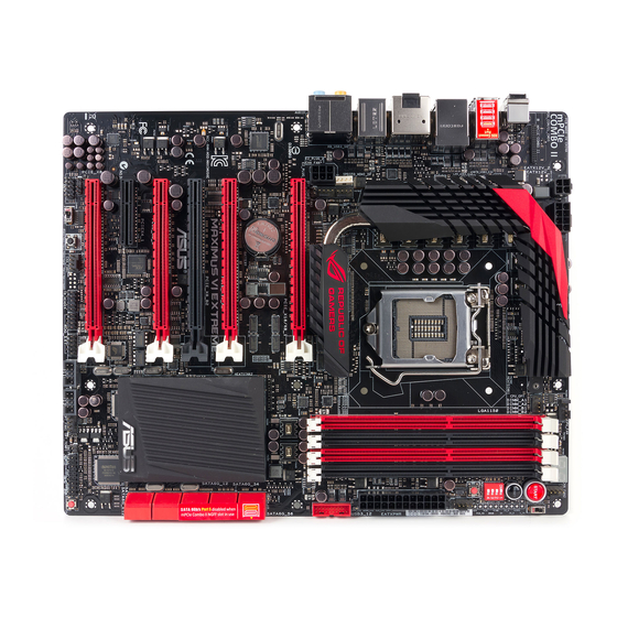
Page 23: Motherboard Layout
1.2.2 Motherboard layout Refer to 1.2.9 Internal connectors and 2.3.1 Rear I/O connection for more information about rear panel connectors and internal connectors. ASUS MAXIMUS VI EXTREME... -
Page 24: Layout Contents
Layout contents Connectors/Jumpers/Buttons and switches/Slots Page 1. Power connectors (24-pin EATXPWR, 8-pin EATX12V, 4-pin EATX12V) 1-43 2. LGA1150 CPU Socket 3. CPU, chassis, and optional fan connectors (4-pin CPU_FAN, 4-pin 1-41 CPU_OPT, 4-pin OPT_FAN1-3, 4-pin CHA_FAN1-3) 4. DDR3 DIMM slots 1-10 5. -
Page 25: Central Processing Unit (Cpu)
Contact your retailer immediately if the PnP cap is missing, or if you see any damage to the PnP cap/socket contacts/motherboard components. ASUS will shoulder the cost of repair only if the damage is shipment/ transit-related. -
Page 26: System Memory
1.2.4 System memory The motherboard comes with four Double Data Rate 3 (DDR3) Dual Inline Memory Modules (DIMM) slots. A DDR3 module is notched differently from a DDR or DDR2 module. DO NOT install a DDR or DDR2 memory module to the DDR3 slot. Recommended memory configurations 1-10 Chapter 1: Product introduction... -
Page 27: Memory Configurations
3.4 Extreme Tweaker menu for manual memory frequency adjustment. • For system stability, use a more efficient memory cooling system to support a full memory load (4 DIMMs) or overclocking condition. ASUS MAXIMUS VI EXTREME 1-11... - Page 28 MAXIMUS VI EXTREME Motherboard Qualified Vendors Lists (QVL) DDR3 3000 MHz capability DIMM socket support Chip Chip Vendors Part No. Size Timing Voltage (Optional) Brand G.SKILL F3-3000C12Q-16GTXDG 16GB (4x4GB) 12-14-14-35 1.65V • • CORSAIR CML8GX3M2A3000C12R 8GB (2x4GB) 12-14-14-36 1.65V •...
- Page 29 11-12-11-30 1.65 • • 16GX(XMP) KINGSTON KHX21C11T3FK8/64X(XMP) 64GB (8x 8GB) 9-9-9-24 • • Patriot PXD38G2133C11K(XMP) 8GB (2x 4GB) 2133 11-11- • 11-27 Team TLD38G2133HC11ABK(XMP) 11-11-11-31 1.65 • • Team TXD34096M2133HC11A- 11-11-11-31 1.65 • • V(XMP) ASUS MAXIMUS VI EXTREME 1-13...
- Page 30 DDR3 2000 MHz capability DIMM socket Chip support Vendors Part No. Size Chip NO. Timing Voltage Brand (Optional) Patriot PV736G2000ELK(XMP) 6GB (3x2GB) 7-7-7-20 1.65 • • Silicon Power SP002GBLYU200S02(XMP) • • Team TXD32048M2000C9(XMP) Team T3D1288RT-20 9-9-9-24 • • Team TXD32048M2000C9-L(XMP) Team T3D1288RT-20 9-9-9-24...
- Page 31 • 32GXM(XMP) (4x8GB) GEIL GET316GB1600 16GB 9-9-9- • • C9QC(XMP) (4x4GB) GEIL GUP34GB1600C 7-7-7- • 7DC(XMP) (2x2GB) GoodRam GR1600D364L9/2G GoodRam GF1008KC-JN • • KINGSTON KHX1600C9D3K3/ 12GB 1.65 • 12GX(XMP) (3x4GB) (continued on the next page) ASUS MAXIMUS VI EXTREME 1-15...
- Page 32 DDR3 1600 MHz capability DIMM socket support Vendors Part No. Size SS/DS Chip Brand Chip NO. Timing Voltage (Optional) KINGSTON KHX1600C9D3K3/ 1.65 • • 6GX(XMP) (3x2GB) KINGSTON KHX1600C9D3P1K2/8G • • (2x4GB) KINGTIGER KTG2G1600PG3(XMP) • • MICRON MT16JTF1G64AZ- MICRON D9PBC • •...
- Page 33 • • KINGMAX FLFF65F-C8KL9 KINGMAX KFC8FNLXF-DXX-15A • • KINGSTON KVR1333D3N9H/4G ELPIDA J2108BDBG-GN-F • • KINGSTON KVR13N9S8H/4 ELPIDA J4208BBBG-GN-F • • KINGTIGER F10DA2T1680 KINGTIGER KTG1333PS1208NST- • • KINGTIGER KTG2G1333PG3 • • (continued on the next page) ASUS MAXIMUS VI EXTREME 1-17...
- Page 34 ASUS exclusively provides hyper DIMM support function. • Hyper DIMM support is subject to the physical characteristics of individual CPUs. Load the X.M.P. settings in the BIOS for the hyper DIMM support. • Visit the ASUS website for the latest QVL. 1-18 Chapter 1: Product introduction...
-
Page 35: Expansion Slots
Slot No. Slot Description PCIe 3.0/2.0 x16/x8_1 slot PCIe 3.0/2.0 x16_A2 slot PCIe 3.0/2.0 x8_B2 slot PCIe 3.0/2.0 x8_3 slot PCIe 2.0/1.1 x4_1 slot PCIe 3.0/2.0 x8_4 slot ASUS MAXIMUS VI EXTREME 1-19... - Page 36 PCIe 3.0 operating mode VGA Configuration SLI/ 3-WAY SLI/ 4-WAY SLI/ Single VGA CrossFireX CrossFireX CrossfireX PCIe 3.0/2.0_x16/x8_1 x16 (Native) x8 (Native) x8 (Native) x8 (Native) – – PCIe 3.0/2.0_x16_A2 – – – PCIe 3.0/2.0_x8_B2 x8 (Native) – – PCIe 3.0/2.0_x8_3 –...
- Page 37 – EHCI# 0 (USB 2.0) – – – – – – shared EHCI# 1 (USB 2.0) – – – – shared – – – XHCI (USB 3.0) – – – – – shared – – ASUS MAXIMUS VI EXTREME 1-21...
-
Page 38: Onboard Buttons And Switches
1.2.6 Onboard buttons and switches Onboard switches and buttons allow you to fine-tune performance when working on a bare or open-case system. This is ideal for overclockers and gamers who continually change settings to enhance system performance. Power-on button The motherboard comes with a power-on button that allows you to power up or wake up the system. - Page 39 BIOS has been restored to its default settings. • We recommend that you download and update to the latest BIOS version from the ASUS website at www.asus.com after using the MemOK! function. ASUS MAXIMUS VI EXTREME 1-23...
- Page 40 BIOS Switch button The motherboard comes with two BIOS. Press the BIOS button to switch BIOS and load different BIOS settings. The nearby BIOS LEDs indicate the BIOS you are using. Slow Mode switch Slow Mode switch allows your system to provide better overclocking margins when using the LN2 cooling system.
- Page 41 When one of the installed PCIe x16 cards is out of order, you can slide the switch to find out the faulty one without removing the cards. Fast Boot switch This switch allows you to enable or disable the Fast Boot feature. When enabled, the system boot speed is accelerated. ASUS MAXIMUS VI EXTREME 1-25...
- Page 42 DirectKey button This feature allows your system to go to the BIOS Setup program with the press of a button. With DirectKey, you can enter the BIOS anytime without having to press the <Del> key during POST. It also allows you to turn on or turn off your system and conveniently enter the BIOS during boot-up.
-
Page 43: Jumpers
POST. It allows the processor to run at an extremely low temperature and helps the system boot fast. * The cold bug is an issue with CPUs that causes to fail to boot at low (usually sub zero) temperatures. ASUS MAXIMUS VI EXTREME 1-27... -
Page 44: Onboard Leds
1.2.8 Onboard LEDs Hard Disk LED The hard disk LED is designed to indicate the hard disk activity. It blinks when data is being written into or read from the hard disk drive. The LED does not light up when there is no hard disk drive connected to the motherboard or when the hard disk drive does not function. - Page 45 ON, in sleep mode, or in soft-off mode. This is a reminder that you should shut down the system and unplug the power cable before removing or plugging in any motherboard component. The illustration below shows the location of the onboard power-on button. ASUS MAXIMUS VI EXTREME 1-29...
- Page 46 BIOS LED The BIOS LEDs help indicate the BIOS activity. Press the BIOS button to switch between BIOS1 and BIOS2 and the LED lights up when the corresponding BIOS is in use. Q-Code LEDs The Q-Code LED design provides you with a 2-digit error code that displays the system status.
- Page 47 Reserved for ASL (see ASL Status Codes section below) Memory Installed 32 – 36 CPU post-memory initialization 37 – 3A Post-Memory System Agent initialization is started 3B – 3E Post-Memory PCH initialization is started DXE IPL is started (continued on the next page) ASUS MAXIMUS VI EXTREME 1-31...
-
Page 48: Q-Code Table
Q-Code table Code Description Memory initialization error. Invalid memory type or incompatible memory 50 – 53 speed Unspecified memory initialization error Memory not installed Invalid CPU type or Speed CPU mismatch CPU self test failed or possible CPU cache error CPU micro-code is not found or micro-code update is failed Not used Power on. - Page 49 Recovery condition triggered by user (Forced recovery) Recovery process started Recovery firmware image is found Recovery firmware image is loaded F5 – F7 Reserved for future AMI progress codes Recovery PPI is not available (continued on the next page) ASUS MAXIMUS VI EXTREME 1-33...
- Page 50 Q-Code table Code Description Recovery capsule is not found Invalid recovery capsule FB – FF Reserved for future AMI error codes DXE Core is started NVRAM initialization Installation of the PCH Runtime Services 63 – 67 CPU DXE initialization is started PCI host bridge initialization System Agent DXE initialization is started System Agent DXE SMM initialization is started...
- Page 51 USB hot plug PCI bus hot plug Clean-up of NVRAM Configuration Reset (reset of NVRAM settings) B8– BF Reserved for future AMI codes CPU initialization error System Agent initialization error (continued on the next page) ASUS MAXIMUS VI EXTREME 1-35...
- Page 52 Q-Code table Code Description PCH initialization error Some of the Architectural Protocols are not available PCI resource allocation error. Out of Resources No Space for Legacy Option ROM No Console Output Devices are found No Console Input Devices are found Invalid password Error loading Boot Option (LoadImage returned error) Boot Option is failed (StartImage returned error)
-
Page 53: Internal Connectors
Native Command Queuing (NCQ) is a protocol allowing hard disk drives to internally optimize the order in which received read and write commands are executed. When using NCQ, set the SATA Mode in the BIOS to [AHCI Mode]. Refer to section • 3.6.3 SATA Configuration for details. ASUS MAXIMUS VI EXTREME 1-37... - Page 54 ASMedia Serial ATA 6.0 Gb/s connectors (7-pin SATA6G_E12/E34 [red]) ® These connectors connect to Serial ATA 6.0 Gb/s hard disk drives via Serial ATA 6.0 Gb/s signal cables. USB 3.0 connector (20-1 pin USB3_12) This connector allows you to connect a USB 3.0 module for additional USB 3.0 front or rear panel ports.
- Page 55 This connector is for an additional Sony/Philips Digital Interface (S/PDIF) port. Connect the S/PDIF Out module cable to this connector, then install the module to a slot opening at the back of the system chassis. The S/PDIF module is purchased separately. ASUS MAXIMUS VI EXTREME 1-39...
- Page 56 Never connect a 1394 cable to the USB connectors. Doing so will damage the motherboard! You can connect the front panel USB cable to the ASUS Q-Connector (USB) first, and then install the Q-Connector (USB) to the USB connector onboard if your chassis supports front panel USB ports.
- Page 57 Ensure to fully insert the 4-pin CPU fan cable to the CPU fan connector. • The CPU_FAN connector supports the CPU fan of maximum 1A (12 W) fan power. • The CPU_FAN connector and CHA_FAN connectors support the ASUS FAN Xpert 2 feature. ASUS MAXIMUS VI EXTREME 1-41...
- Page 58 Front panel audio connector (10-1 pin AAFP) This connector is for a chassis-mounted front panel audio I/O module that supports either HD Audio or legacy AC`97 audio standard. Connect one end of the front panel audio I/O module cable to this connector. •...
- Page 59 1000W power or above to ensure the system stability. • If you are uncertain about the minimum power supply requirement for your system, refer to the Recommended Power Supply Wattage Calculator at http://support.asus. com/PowerSupplyCalculator/PSCalculator.aspx?SLanguage=en-us for details. ASUS MAXIMUS VI EXTREME...
-
Page 60: System Panel Connector
System panel connector (20-8 pin PANEL) This connector supports several chassis-mounted functions. • System power LED (2-pin PLED) This 2-pin connector is for the system power LED. Connect the chassis power LED cable to this connector. The system power LED lights up when you turn on the system power, and blinks when the system is in sleep mode. - Page 61 The optional fan 1/2/3 (OPT_FAN1/2/3) can work with the temperature sensors for a better cooling effect. The thermal sensor cables are purchased separately. ASUS MAXIMUS VI EXTREME 1-45...
- Page 62 DirectKey connector (2-pin DRCT) This connector is for the chassis-mounted button that supports the DirectKey function. Connect the button cable that supports DirectKey, from the chassis to this connector on the motherboard. Ensure that your chassis comes with the extra button cable that supports the DirectKey feature.
- Page 63 ROG Extension - OC Panel connector (18-1 pin ROG_EXT) This connector is for the OC Panel. The OC Panel allows you to perform overclocking without going to the BIOS settings, loading the OS, or using overclocking software utilities. ASUS MAXIMUS VI EXTREME 1-47...
-
Page 64: Probeit
1.2.10 ProbeIt The ROG ProbeIt allows you to detect your system’s current voltage and OC settings. Use a multimeter to measure the ProbeIt points even during overclocking. See the illustration below to locate the respective ProbeIt points. Using ProbeIt You may connect the multitester to the motherboard as shown on the following figure. The photos above are for reference only, the actual motherboard layout and measure points location may differ by models. -
Page 65: Chapter 2: Basic Installation
The diagrams in this section are for reference only. The motherboard layout may vary with models, but the installation steps are the same for all models. Install the ASUS Q-Shield to the chassis rear I/O panel. Place the motherboard into the chassis, ensuring that its rear I/O ports are aligned to the chassis’... - Page 66 Place nine screws into the holes indicated by circles to secure the motherboard to the chassis. DO NOT overtighten the screws! Doing so can damage the motherboard. Chapter 2: Basic Installation...
-
Page 67: Cpu Installation
2.1.2 CPU installation Ensure that you install the correct CPU designed for LGA1150 socket only. DO NOT install a CPU designed for LGA1155 and LGA1156 sockets on the LGA1150 socket. ASUS MAXIMUS VI EXTREME... -
Page 68: Cpu Heatsink And Fan Assembly Installation
2.1.3 CPU heatsink and fan assembly installation Apply the Thermal Interface Material to the CPU heatsink and CPU before you install the heatsink and fan if necessary. To install the CPU heatsink and fan assembly Chapter 2: Basic Installation... - Page 69 To uninstall the CPU heatsink and fan assembly ASUS MAXIMUS VI EXTREME...
-
Page 70: Dimm Installation
2.1.4 DIMM installation To remove a DIMM Chapter 2: Basic Installation... -
Page 71: Atx Power Connection
2.1.5 ATX Power connection ASUS MAXIMUS VI EXTREME... -
Page 72: Sata Device Connection
2.1.6 SATA device connection Chapter 2: Basic Installation... -
Page 73: Front I/O Connector
2.1.7 Front I/O Connector To install ASUS Q-Connector To install USB 2.0 connector To install front panel audio connector AAFP USB 2.0 To install USB 3.0 connector USB 3.0 ASUS MAXIMUS VI EXTREME... -
Page 74: Expansion Card Installation
2.1.8 Expansion Card installation To install PCIe x16 cards 2-10 Chapter 2: Basic Installation... -
Page 75: Mpcie Combo Ii Installation
Align and insert the M.2 (NGFF) SSD module into the M.2 slot. The M.2 (NGFF) SSD module fits in one orientation only. If it does not fit, try reversing it. ASUS MAXIMUS VI EXTREME 2-11... - Page 76 Replace the metal cover and secure the back of the metal cover with the two short screws that you removed in step 1. Secure the front of the metal cover with the long screw that you removed in step 2. Installing the mPCIe Combo II card To install the mPCIe Combo II card to your motherboard: Remove the black screw near the...
- Page 77 Secure the mPCIe Combo II card either to the motherboard or the rear I/O shield using the black screw removed in step 1. ASUS MAXIMUS VI EXTREME 2-13...
- Page 78 Installing the Wi-Fi antenna connector If you installed a Wi-Fi module on the mPCIe Combo II, you would need to install the Wi-Fi antenna connector. To install the Wi-Fi antenna connector: Remove the bolt from the Wi-Fi antenna connector but leave the washer on the washer connector.
-
Page 79: Bios Update Utility
• Updating BIOS may have risks. If the BIOS program is damaged during the process and results to the system’s failure to boot up, please contact your local ASUS Service Center. ASUS MAXIMUS VI EXTREME... -
Page 80: Motherboard Rear And Audio Connections
6. ROG Connect button 7. ASMedia USB 3.0 port E3 and E4, support ASUS USB 3.0 Boost Turbo Mode 8. ASMedia USB 3.0 port E1 and E2 , support ASUS USB 3.0 Boost Turbo Mode 9. HDMI port 10. DisplayPort 11. -
Page 81: Audio I/O Connections
Mic In Mic In Mic In Orange – – Center/Subwoofer Center/Subwoofer Black – Rear Speaker Out Rear Speaker Out Rear Speaker Out Gray – – – Side Speaker Out 2.3.2 Audio I/O connections Audio I/O ports ASUS MAXIMUS VI EXTREME 2-17... - Page 82 Connect to Headphone and Mic Connect to Stereo Speakers Connect to 2.1 channel Speakers 2-18 Chapter 2: Basic Installation...
- Page 83 Connect to 4.1 channel Speakers Connect to 5.1 channel Speakers ASUS MAXIMUS VI EXTREME 2-19...
- Page 84 Connect to 7.1 channel Speakers 2-20 Chapter 2: Basic Installation...
-
Page 85: Oc Panel
Value up Button OK button Left Arrow button Right Arrow button Clear button Reset button Value Down button Fan connectors 1,2 VGA hotwire Fan connectors 3,4 connectors VGA hotwire Pause/Slow Mode OC Panel cover ASUS MAXIMUS VI EXTREME 2-21... - Page 86 OC Panel LCM Display in Normal Mode OC Panel LCM Display in Extreme Mode 2-22 Chapter 2: Basic Installation...
-
Page 87: Setting Up Your Oc Panel In Normal Mode
(2) screws. Align and insert the OC Panel into the OC Panel 5.25-inch drive bay metal case. OC Panel fits in one orientation only. If it does not fit, try reversing it. ASUS MAXIMUS VI EXTREME 2-23... - Page 88 Secure the OC Panel to the OC Panel 5.25-inch drive bay metal case with the two (2) screws. Ensure that the OC Panel fits snugly into the OC Panel 5.25-inch drive bay metal case. Shut down your computer. Open your computer chassis and remove the front cover of an available 5.25-inch drive bay.
-
Page 89: Setting Up Your Oc Panel In Extreme Mode
SATA Power cable (B) to the OC Panel. Locate the ROG_EXT connector on the motherboard and connect the OC Panel cable. Boot your computer. Press the OC Panel power button to turn on the OC Panel LCM display. ASUS MAXIMUS VI EXTREME 2-25... -
Page 90: Starting Up For The First Time
Starting up for the first time After making all the connections, replace the system case cover. Ensure that all switches are off. Connect the power cord to the power connector at the back of the system chassis. Connect the power cord to a power outlet that is equipped with a surge protector. Turn on the devices in the following order: Monitor External SCSI devices (starting with the last device on the chain) -
Page 91: Chapter 3: Bios Setup
BIOS setup Knowing BIOS The new ASUS UEFI BIOS is a Unified Extensible Interface that complies with UEFI architecture, offering a user-friendly interface that goes beyond the traditional keyboard- only BIOS controls to enable a more flexible and convenient mouse input. You can easily navigate the new UEFI BIOS with the same smoothness as your operating system. -
Page 92: Bios Setup Program
BIOS setup program Use the BIOS Setup to update the BIOS or configure its parameters. The BIOS screen include navigation keys and brief onscreen help to guide you in using the BIOS Setup program. Entering BIOS at startup To enter BIOS Setup at startup, press <Delete> during the Power-On Self Test (POST). If you do not press <Delete>, POST continues with its routines. -
Page 93: Ez Mode
Power Saving mode mode • The boot device options vary depending on the devices you installed to the system. The Boot Menu (F8) button is available only when the boot device is installed to the • system. ASUS MAXIMUS VI EXTREME... -
Page 94: Advanced Mode
3.2.2 Advanced Mode The Advanced Mode provides advanced options for experienced end-users to configure the BIOS settings. The figure below shows an example of the Advanced Mode. Refer to the following sections for the detailed configurations. To access the Advanced Mode, click Exit, then select Advanced Mode or press F7 hotkey. Menu items Menu bar General help... -
Page 95: Menu Items
This button allows you to enter notes of the activities that you have done in BIOS. • The Quick Note function does not support the following keyboard functions: delete, cut, copy and paste. • You can only use the alphanumeric characters to enter your notes. ASUS MAXIMUS VI EXTREME... -
Page 96: My Favorites
Last Modified button This button shows the items that you last modified and saved in BIOS Setup. My Favorites MyFavorites is your personal space where you can easily save and access your favorite BIOS items. Adding items to My Favorites To add frequently-used BIOS items to My Favorites: Use the arrow keys to select an item that you want to add. -
Page 97: Extreme Tweaker Menu
Be cautious when changing the settings of the Extreme Tweaker menu items. Incorrect field values can cause the system to malfunction. The configuration options for this section vary depending on the CPU and DIMM model you installed on the motherboard. Scroll down to display other BIOS items. ASUS MAXIMUS VI EXTREME... - Page 98 The [X.M.P.] configuration option appears only when you install memory modules supporting the eXtreme Memory Profile (X.M.P.) Technology. ASUS MultiCore Enhancement [Enabled] Default is set to [Auto] for maximum performance under XMP/Manual/ [Auto] User-defined memory frequency mode.
- Page 99 Allows you to set the uncore ratio of the processor to its possible minimum value. Configuration options: [Auto] [1] - [80] Max CPU Cache Ratio [Auto] Allows you to set the uncore ratio of the processor to its possible maximum value. Configuration options: [Auto] [1] - [80] ASUS MAXIMUS VI EXTREME...
- Page 100 Internal PLL Overvoltage [Auto] Allows you to enable the internal PLL voltage for K-SKU CPUs to get the extreme overclocking capability. Configuration options: [Auto] [Enabled] [Disabled] BCLK Frequency : DRAM Frequency Ratio [Auto] Allows you to set the BCLK Frequency to DRAM Frequency ratio. [Auto] The ratio will be set to the optimized settings.
- Page 101 DRAM WRITE to READ Delay [Auto] Configuration options: [Auto] [1] – [15] DRAM CKE Minimum pulse width [Auto] Configuration options: [Auto] [1] – [15] DRAM CAS# Write Latency [Auto] Configuration options: [Auto] [1] – [31] ASUS MAXIMUS VI EXTREME 3-11...
- Page 102 RTL IOL control DRAM RTL Initial Value [Auto] Configuration options: [Auto] [1] - [63] DRAM RTL (CHA_R0D0) [Auto] Configuration options: [Auto] [1] - [63] DRAM RTL (CHA_R0D1) [Auto] Configuration options: [Auto] [1] - [63] DRAM RTL (CHA_R1D0) [Auto] Configuration options: [Auto] [1] - [63] DRAM RTL (CHA_R1D1) [Auto] Configuration options: [Auto] [1] - [63] DRAM RTL (CHB_R0D0) [Auto]...
- Page 103 Allows you to enable or disable the Channel B DIMM slots with the following configuration options: [Enable Both DIMMS] [Disable DIMM0] [Disable DIMM1] [Disable Both DIMMS] Scrambler Setting [Optimized ...] Set this item to [Optimized (ASUS)] to enhance system stability. Configuration options: [Optimized (ASUS)] [Default (MRC)] ASUS MAXIMUS VI EXTREME 3-13...
- Page 104 MCH Full Check [Auto] [Auto] Select to automatically choose the mode. [Enabled] Select this item to enhance system stability. [Disabled] Selecting this item may enhance the DRAM overclocking capablity. DQ Sense Amplifier [Auto] Reducing usually helps overclocking and over-voltage. Configuration options: [Auto] [+16] – [-29] DQS Sense Amplifier [Auto] Reducing usually helps overclocking and over-voltage.
- Page 105 The following item appears only when you set the CPU Voltage Frequency to [Manual]. CPU Fixed Frequency [XXXX] This item allows you to set a fixed CPU frequency The configuration options ranges from 300kHz to 1000kHz. Use the <+> or <-> keys to adjust the interval. ASUS MAXIMUS VI EXTREME 3-15...
- Page 106 Allows you to set the power phase control of the CPU. [Standard] Set the phase control based on the CPU command. [Optimized] Set the ASUS optimized phase tuning profile. [Extreme] Set the full phase mode [Manual Set manually to a faster phase response to increase system...
- Page 107 Allows you to set the power phase control of the DRAM. [Auto] Allows you to set the Auto mode. [Optimized] Allows you to set the ASUS optimized phase tuning profile. [Extreme] Allows you to set the full phase mode. ASUS MAXIMUS VI EXTREME...
- Page 108 Tweakers’ Paradise The subitems in this menu allow you to set the CPU ratio and features. VCCIN Shadow Voltage [Auto] Pseudo Voltage for VCCIN. Configuration options: [Auto] [0.800] – [2.440V] Termination Anti-Aliasing [Auto] Termination Anti-Aliasing. Configuration options: [Auto] [Disabled] [Enabled] Initial PLL Termination Voltage [Auto] Initial Voltage at which CPU BCLKs are terminated.
- Page 109 PCIE Clock Amplitude [Auto] Adjust the magnitude of the PCIE Clocks. Higher may be better. Configuration options: [Auto] [+5] - [-4] Internal Graphics [Auto] Keep IGD enabled based on setup options. Configuration options: [Auto] [Disabled] [Enabled] ASUS MAXIMUS VI EXTREME 3-19...
-
Page 110: Cpu Power Management
CPU Power Management The subitems in this menu allow you to set the CPU ratio and features. Enhanced Intel SpeedStep Technology [Enabled] Allows the operating system to dynamically adjust the processor voltage and cores frequency to decrease the average power consumption and decrease average heat production. - Page 111 Allows you to set the power saving threshold for overclocking. A low value provides enough power for overclocking. A high value provides a better power saving condition. The value ranges from: Level 1 0 - 80A Level 2 0 - 50A Level 3 0 - 30A ASUS MAXIMUS VI EXTREME 3-21...
-
Page 112: Main Menu
Main menu The Main menu screen appears when you enter the Advanced Mode of the BIOS Setup program. The Main menu provides you an overview of the basic system information, and allows you to set the system date, time, language, and security settings. Security The Security menu items allow you to change the system security settings. -
Page 113: Administrator Password
Installed. To set a user password: Select the User Password item and press <Enter>. From the Create New Password box, key in a password, then press <Enter>. Confirm the password when prompted. ASUS MAXIMUS VI EXTREME 3-23... - Page 114 To change a user password: Select the User Password item and press <Enter>. From the Enter Current Password box, key in the current password, then press <Enter>. From the Create New Password box, key in a new password, then press <Enter>. Confirm the password when prompted.
-
Page 115: Advanced Menu
The Advanced menu items allow you to change the settings for the CPU and other system devices. Be cautious when changing the settings of the Advanced menu items. Incorrect field values can cause the system to malfunction. ASUS MAXIMUS VI EXTREME 3-25... -
Page 116: Cpu Configuration
3.6.1 CPU Configuration The items in this menu show the CPU-related information that the BIOS automatically detects. The items in this menu may vary based on the CPU installed. Intel Adaptive Thermal Monitor [Enabled] [Enabled] Enables the overheated CPU to throttle its clock speed to cool down. [Disabled] Disables the CPU thermal monitor function. - Page 117 The CPU runs at its default speed. [Enabled} The operating system controls the CPU speed. Turbo Mode [Enabled] Allows you to set the processor cores to run faster than the marked frequency in a specific condition. Configuration options: [Enabled] [Disabled] ASUS MAXIMUS VI EXTREME 3-27...
- Page 118 CPU C States [Auto] Allows you to enable or disable the CPU C states. Configuration options: [Auto] [Enabled] [Disabled] The following items appear only when you set the CPU C States to [Enabled]. Enhanced C1 state [Enabled] Allows your processor to reduce power when the system is in idle mode. Configuration options: [Enabled] [Disabled] CPU C3 Report [Enabled] Allows you to disable or enable the CPU C3 report to the operating system.
-
Page 119: Pch Configuration
Configuration options: []Auto] [Disabled] [Enabled] ASPM Support [Disabled] Allows you to set the ASPM level. Configuration options: [Disabled] [Auto] [L0s] [L1] [L0sL1] PCIe Speed [Auto] Allows you to select the PCI Express port speed. Configuration options: [Auto] [Gen1] [Gen2] ASUS MAXIMUS VI EXTREME 3-29... -
Page 120: Intel Smart Connect Technology
Intel Rapid Start Technology [Disabled] ® Allows you to enable or disable Intel Rapid Start Technology. The following items appear only when you set the Intel Rapid Start Technology to ® [Enabled]. Entry on S3 RTC Wake [Enabled] The system automatically wakes up and set to Rapid Start Technology S4 mode. Configuration options: [Enabled] [Disabled] Entry After [0] This item appears only when you set the Entry on S3 RTC Wake to... -
Page 121: Sata Configuration
Set to [RAID] when you want to create a RAID configuration from the SATA hard disk drives. Aggressive LPM Support [Auto] Allows you to enable the PCH to aggressively enter link power state. Configuration options: [Auto] [Disabled] [Enabled] ASUS MAXIMUS VI EXTREME 3-31... -
Page 122: System Agent Configuration
S.M.A.R.T. Status Check [Enabled] S.M.A.R.T. (Self-Monitoring, Analysis and Reporting Technology) is a monitor system. When read/write of your hard disk errors occur, this feature allows the hard disk to report warning messages during the POST. Configuration options: [Enabled] [Disabled] Hot Plug [Disabled] (SATA6G_1 - SATA6G_6 [Red]) These items appear only when you set the SATA Mode Selection item to [AHCI] or [RAID], and allow you to enable/disable SATA Hot Plug Support. -
Page 123: Memory Configuration
Configuration options: [Disabled] [Auto] [ASPM L0s] [ASPM L1] [ASPM L0sL1] Memory Configuration Allows you to configure the memory configuration parameters. Memory Remap [Enabled] Allows you to enable remapping the memory above 4GB. Configuration options: [Enabled] [Disabled] ASUS MAXIMUS VI EXTREME 3-33... -
Page 124: Usb Configuration
3.6.5 USB Configuration The items in this menu allow you to change the USB-related features. The USB Devices item shows the auto-detected values. If no USB device is detected, the item shows None. Legacy USB Support [Enabled] [Enabled] Enables the support for USB devices on legacy operating systems (OS). [Disabled] The USB devices can be used only for the BIOS setup program. -
Page 125: Platform Misc Configuration
The following item appears only when you set the PCI Express Native Power Management to [Enabled]. Native ASPM [Disabled] [Enabled] Vista controls the ASPM support for the device. [Disabled] BIOS controls the ASPM support for the device. ASUS MAXIMUS VI EXTREME 3-35... -
Page 126: Onboard Devices Configuration
3.6.7 Onboard Devices Configuration Scroll down to view the other BIOS items. HD Audio Controller [Enabled] [Enabled] Enables the High Definition Audio Controller. [Disabled] Disables the controller. The following items appear only when you set the HD Audio Controller to [Enabled]. Front Panel Type [HD] Allows you to set the front panel audio connector (AAFP) mode to legacy AC’97 or high-definition audio depending on the audio standard that the front panel audio... - Page 127 Intel PXE OPROM [Disabled] This item appears only when you set the previous item to [Enabled]. It allows you to enable or disable the PXE OptionRom of the Intel I217-V LAN controller. ® Configuration options: [Enabled] [Disabled] ASUS MAXIMUS VI EXTREME 3-37...
-
Page 128: Apm
3.6.8 ErP Ready [Disabled] Allows you to switch off some power at S4+S5 or S5 to get the system ready for ErP requirement. When set to [Enabled], all other PME options will be switched off. Configuration options: [Disabled] [Enabled (S4+S5) ] [Enabled (S5)] Restore AC Power Loss [Power Off] [Power On] The system goes into ON state after an AC power loss. -
Page 129: Network Stack Configuration
This item allows ROG animation on the upper left corner ot the UEFI BIOS Utility screen when enabled. Configuration options: [Disabled] [Enabled] Onboard LED [Enabled] This item allows you to enable or disable all the onboard LEDs. Configuration options: [Enabled] [Disabled] ASUS MAXIMUS VI EXTREME 3-39... -
Page 130: Monitor Menu
Monitor menu The Monitor menu displays the system temperature/power status, and allows you to change the fan settings. Anti Surge Support [Enabled] This item allows you to enable or disable the Anti Surge function. Configuration options: [Disabled] [Enabled] Voltage Monitor CPU Core 0-3 Voltage;... -
Page 131: Fan Speed Control
Use the <+> and <-> keys to adjust the minimum CPU fan duty cycle. The values range from 40% to 100%. When the CPU temperature is under its CPU lower temperature setting, the CPU fan will operate at the minimum duty cycle. ASUS MAXIMUS VI EXTREME 3-41... - Page 132 Chassis Q-Fan Control 1-3 [Disabled] [Disabled] Disables the Chassis Q-Fan control feature. [Enabled] Enables the Chassis Q-Fan control feature. Chassis Fan Speed Low Limit 1-3 [600 RPM] This item appears only when you enable the Chassis Q-Fan Control feature and allows you to disable or set the chassis fan warning speed.
- Page 133 Allows you to set the optional fans’ low speed temperature. Configuration options: [25%] [30%] [35%] [40%] OPT1-3 Full Speed Temp [60%] Allows you to set the optional fans’ full speed temperature. Configuration options: [60%] [70%] [80%] [90%] ASUS MAXIMUS VI EXTREME 3-43...
-
Page 134: Boot Menu
Boot menu The Boot menu items allow you to change the system boot options. Scroll down to display the other BIOS items. Boot Configuration Fast Boot [Disabled] [Disabled] Allows your system to go back to its normal boot speed. [Enabled] Allows your system to accelerate the boot speed. - Page 135 [On] Set the power-on state of the NumLock to [Off]. [Off] Wait For ‘F1’ If Error [Enabled] [Disabled] Disables the function. [Enabled] The system waits for the <F1> key to be pressed when error occurs. ASUS MAXIMUS VI EXTREME 3-45...
- Page 136 Option ROM Messages [Force BIOS] [Force BIOS] The third-party ROM messages will be forced to display during the boot sequence. [Keep Current] The third-party ROM messages will be displayed only if the third-party manufacturer had set the add-on device to do so. Interrupt 19 Capture [Enabled] When set to [Enabled], allows the option ROMs to trap Interrupt 19.
-
Page 137: Secure Boot
Press <F5> when ASUS Logo appears. Press <F8> after POST. • To select the boot device during system startup, press <F8> when ASUS Logo appears. Boot Override These items displays the available devices. The number of device items that appears on the screen depends on the number of devices installed in the system. -
Page 138: Tools Menu
3.9.1 ASUS EZ Flash 2 Utility Allows you to run ASUS EZ Flash 2. When you press <Enter>, a confirmation message appears. Use the left/right arrow key to select between [Yes] or [No], then press <Enter> to confirm your choice. -
Page 139: Asus Spd Information
• We recommend that you update the BIOS file only coming from the same memory/ CPU configuration and BIOS version. 3.9.3 ASUS SPD Information Allows you to view the DRAM SPD information. ASUS MAXIMUS VI EXTREME 3-49... -
Page 140: Bios Flashback
3.9.4 BIOS Flashback Allows you select copy and boot from either BIOS1 or BIOS2. Force BIOS2 Boot Select [Yes] to force the boot using BIOS2. COPY BIOS1 to BIOS2 Select [Yes] to copy the content of BIOS1 to BIOS2. 3-50 Chapter 3: BIOS setup... -
Page 141: Exit Menu
This option allows you to enter the EZ Mode screen. Launch EFI Shell from filesystem device This option allows you to attempt to launch the EFI Shell application (shellx64.efi) from one of the available filesystem devices. ASUS MAXIMUS VI EXTREME 3-51... -
Page 142: Updating Bios
Inappropriate BIOS updating may result in the system’s failure to boot. Carefully follow the instructions of this chapter to update your BIOS if necessary. Visit the ASUS website at www.asus.com to download the latest BIOS file for this motherboard. The following utilities allow you to manage and update the motherboard BIOS setup program. -
Page 143: Asus Ez Flash 2
3.11.1 ASUS EZ Flash 2 ASUS EZ Flash 2 allows you to update the BIOS without having to use a bootable floppy disk or an OS-based utility. Before you start using this utility, download the latest BIOS from the ASUS website at www.asus.com. -
Page 144: Asus Crashfree Bios 3
The BIOS file in the motherboard support DVD may be older than the BIOS file published on the ASUS official website. If you want to use the newer BIOS file, download the file at support.asus.com and save it to a USB flash drive. -
Page 145: Asus Bios Updater
3.11.3 ASUS BIOS Updater The ASUS BIOS Updater allows you to update the BIOS in DOS environment. This utility also allows you to copy the current BIOS file that you can use as a backup when the BIOS fails or gets corrupted during the updating process. - Page 146 At the FreeDOS prompt, type bupdater /pc /g and press <Enter>. D:\>bupdater /pc /g The BIOS Updater screen appears as below. ASUSTek BIOS Updater for DOS V1.30 [2012/05/22] FLASH TYPE: MX1C 25L1065A Current ROM Update ROM BOARD: MAXIMUS VI EXTREME BOARD: UNKNOWN VER: 0204 VER: UNKNOWN DATE: 01/01/2012...
- Page 147 Select the Load Optimized Defaults item under the Exit BIOS menu. See Chaper 3 of your motherboard user manual for details. • Ensure to connect all SATA hard disk drives after updating the BIOS file if you have disconnected them. ASUS MAXIMUS VI EXTREME 3-57...
-
Page 148: Rog Ssd Secure Erase
To launch ROG SSD Secure Erase, click Tool > ROG SSD Secure Erase on the Advanced mode menu. Check the ASUS support site for a full list of SSDs tested with Secure Erase. The drive may become unstable if you run Secure Erase on an incompatible SSD. -
Page 149: Chapter 4: Software Support
Support DVD information The contents of the support DVD are subject to change at any time without notice. Visit the ASUS website at www.asus.com for updates. 4.2.1 Running the support DVD Ensure that you have an Administrator account before running the support DVD in... -
Page 150: Obtaining The Software Manuals
The software manual files are in Portable Document Format (PDF). Install the Adobe ® Reader from the Utilities tab before opening the files. Acrobat ® To read about your motherboard’s utility guide: Click Manual tab > ASUS Motherboard Utility Guide. Chapter 4: Software support... - Page 151 Some software manuals are provided in different languages. Open the language’s folder to view the software manual. The screenshots in this section are for reference only. The actual software manuals containing in the support DVD vary by models. ASUS MAXIMUS VI EXTREME...
-
Page 152: Software Information
View the online help or readme file that came with the software application for more information. AI Suite 3 AI Suite 3 is an all-in-one interface that integrates several ASUS utilities and allows you to launch and operate these utilities simultaneously. Installing AI Suite 3 •... - Page 153 Launching AI Suite 3 Windows 7 OS ® From the Desktop, click Start > All Programs > ASUS > AI Suite 3 > AI Suite 3. You can also launch AI Suite 3 in Windows 7 by clicking on the Notification area.
- Page 154 Some functions in the AI Suite 3 main menu in this user manual may vary depending on the motherboard model. • Refer to the software manual in the support DVD or visit the ASUS website at www.asus.com for detailed software configuration. Chapter 4: Software support...
-
Page 155: Dual Intelligent Processors 4 With 4-Way Optimization
Click or tap this 4-Way Optimization Click or tap to view the 4-Way button to auto-detect and tune the best Optimization report settings for your system DO NOT remove your fan during the tuning process. ASUS MAXIMUS VI EXTREME... - Page 156 Using 4-Way Optimization Click or tap the 4-Way Optimization button then click or tap Start to auto-detect the best settings based on actual usage. Click or tap to go back to Click or tap to view Click or tap to start the 4-Way Optimization more settings auto-tuning...
-
Page 157: Cpu Frequency
TPU. Refer to section Extreme Tweaker menu in the BIOS chapter of your motherboard user manual for details. • The CPU Frequency bars show the status of the CPU cores, which vary with your CPU model. ASUS MAXIMUS VI EXTREME... -
Page 158: Gpu Boost
GPU Boost Click adjust the GPU Graphics voltage Click to adjust the CPU graphics frequency Click to apply the adjustments Click to undo the Click to load the Click to save the adjustments saved profile adjustment into a profile • The overclocking result varies with the CPU model and the system configuration. -
Page 159: Energy Processing Unit (Epu)
Away Mode and move the sliders to adjust monitor and system sleep time Click or tap to apply the adjustments Click or tap to apply the Click or tap to undo the default settings adjustments ASUS MAXIMUS VI EXTREME 4-11... - Page 160 Max Power Saving Move the Tick to select Voltage slider to adjust Decrement setting the CPU Input Voltage Move the slider to adjust the maximum CPU power Tick to enable Away Mode then move the sliders to adjust monitor and system sleep time Click or tap to apply the...
- Page 161 * The system automatically sets the default to [Extreme] when using the Intel iGPU. ® CPU Power Thermal Control A higher temperature brings a wider CPU power thermal range and extends the overclocking tolerance to enlarge the overclocking potential. ASUS MAXIMUS VI EXTREME 4-13...
- Page 162 DRAM Power Phase Control Select Extreme for full phase mode to increase system performance or select Optimized for ASUS optimized phase tuning profile to increase the DRAM power efficiency. • The actual performance boost may vary depending on your CPU specification.
-
Page 163: Fan Xpert 2
Click or tap to undo the changes Click or tap to apply the changes Click or tap to go back Click or tap to switch between the CPU to the previous screen and chassis fan screens ASUS MAXIMUS VI EXTREME 4-15... - Page 164 RPM Mode RPM Mode allows you to set the fan speed at its fixed value when the CPU temperature drops 75 C and below. Drag the slider up or down to adjust the fan’s speed Click or tap to go back to Click or tap to switch between the the previous screen CPU and chassis fan screens...
-
Page 165: Ai Charger
• To ensure normal charging function, disconnect and reconnect your USB device every time you enable or disable Ai Charger+. • Ai Charger+ does not support USB hubs, USB extension cables, and generic USB cables. ASUS MAXIMUS VI EXTREME 4-17... -
Page 166: Usb Charger
Rear I/O connection of your user manual for more details. • USB Charger+ does not support USB hubs, USB extension cables, and generic USB cables. • USB Charger+ may not recognize some ASUS devices due to varying design. 4-18 Chapter 4: Software support... -
Page 167: Wi-Fi Engine
The Client mode allows you to connect your system to a wireless network. To use the client mode: Click or tap Client Mode to launch Network Connections. From the Network Connections window, select a network adapter. ASUS MAXIMUS VI EXTREME 4-19... - Page 168 From the list of available networks, select a network that you want to connect to. Some networks may require you to key in a password. Using the AP Mode The AP mode allows you to set your system as an access point for other wireless-enabled devices.
-
Page 169: Usb 3.0 Boost
• USB 3.0 Boost automatically detects the USB 3.0 devices that support UASP. For a list of UASP-supported USB 3.0 devices, visit the ASUS website at www.asus.com. • The data transfer speed varies with USB devices. For a higher data transfer performance, use a USB 3.0 device. -
Page 170: Usb Bios Flashback
4.4.6 USB BIOS Flashback USB BIOS Flashback allows you to check and save the latest BIOS version to a USB storage device. Use this utility to quickly check for the latest available BIOS and set the BIOS download schedule. Launching USB BIOS Flashback To launch USB BIOS Flashback, click or tap on the top-right corner of the AI Suite 3 main menu, then select USB BIOS Flashback. - Page 171 BIOS version. After the utility detects a new BIOS, from the Save to: field, click or tap select the USB flash drive, then click or tap Download. After the download is complete, click or tap OK. ASUS MAXIMUS VI EXTREME 4-23...
-
Page 172: Wi-Fi Go
4.4.7 Wi-Fi GO! Wi-Fi GO! is ASUS-exclusive Wi-Fi utility that allows you to wirelessly stream your media files to HDTV device/display, control your computer using your smart device, transfer files to your smart device, and provides access to your files stored in your cloud storage. - Page 173 Launching Wi-Fi GO! To launch Wi-Fi GO!, click or tap the on the top-right corner of the AI Suite 3 main menu, then select Wi-Fi GO! Click or tap to set a password Wi-Fi GO! menu ASUS MAXIMUS VI EXTREME 4-25...
- Page 174 • Ensure that the ASUS AI Suite 3 utility is active when using Wi-Fi GO!. Wi-Fi GO! & NFC Remote Wi-Fi GO! & NFC Remote allows you to remotely control your computer using your smart device.
- Page 175 Click or tap Cloud GO! > Enter. Log in to your cloud accounts, then click or tap Sign In. • To log in to your ASUS Webstorage account, key in your user name and password. accounts, click or tap Sign in. Cloud •...
- Page 176 Click or tap a specific icon to move, upload, rename, create folder, download, delete or refresh your cloud contents Click or tap to open a cloud storage account Tick to select contents Click or tap to sign out Click or tap to go Click or tap to go back to Click or tap to synchronize your files to back to Wi-Fi GO!
- Page 177 Tick the cloud storage account then tap OK. Tick Backup to PC under (C:\MyFavorite\) • if you want to save a backup in your computer. • Open the Wi-Fi GO! folder to view all synced files. ASUS MAXIMUS VI EXTREME 4-29...
- Page 178 Remote Desktop Remote Desktop allows you to remotely control your desktop in real-time using your smart device. Using Remote Desktop To use Remote Desktop: On your smart device, tap Remote Desktop > Enter. Wait for the smart device to connect with your computer. 7, you can select Extended Mode or Main To operate Remote Desktop in Windows ®...
- Page 179 Click or tap to go back to and media file in play back to Wi-Fi GO! the previous screen screen Selecting a receiver To select a receiver: Click or tap Tick to select a receiver, then click or tap OK. ASUS MAXIMUS VI EXTREME 4-31...
- Page 180 Adding media files To add media files: From the Music , Video, or Photo screen, click or tap Click or tap Add then search the files that you want to add. Click or tap OK. Deleting media files To delete media files: From the Music, Video, or Photo screen, click or tap Tick the files that you want to delete,...
-
Page 181: File Transfer
Click or tap browse to select the destination Click or tap to apply the Click or tap to go Click or tap to go back to changes back to Wi-Fi GO!/ the previous screen Remote GO! screen ASUS MAXIMUS VI EXTREME 4-33... - Page 182 Right-click or long tap the file then select Send to > [Device Name]. After the file transfer is complete, click or tap OK. • If you are using an iOS smart device, you can only receive files in PNG, BMP, JPG, GIF, and TIFF formats.
- Page 183 To do this, tap Smart Sensor Control then tap Enable on either the gyroscope or microphone function. • This feature is also supported in Windows ® ASUS MAXIMUS VI EXTREME 4-35...
- Page 184 The Smart Sensor Control in Windows 8 environment features the microphone function for ® voice chat and recording. It also has the gyroscope function that allows you to use your smart device as a remote control for gyroscope-enabled apps. In your smart device, tap Smart Sensor Control > Enable on the virtual microphone or gyroscope functions.
- Page 185 Click or tap to go back Click or tap to go back to Click or tap to apply the settings to Wi-Fi GO! screen the previous screen ASUS MAXIMUS VI EXTREME 4-37...
- Page 186 In the Proximity tab, select an action from the Action: field. To save the action as a profile, click or tap Apply & Save. To apply the action without saving as a profile, click or tap Apply. Your smart device must have a proximity sensor function to support this feature. Click or tap to apply and save the settings as...
- Page 187 Ensure to enable the Capture & Send feature in your smart device. To do this, tap Capture & Send then tap Enable. In your smart device, tap Capture & Send then tap Enter. Tap the file then select an app that you want to open the file with. ASUS MAXIMUS VI EXTREME 4-39...
-
Page 188: Ez Update
4.4.8 EZ Update EZ Update is a utility that allows you to automatically update your motherboard’s software, drivers and BIOS easily. With this utlity, you can also manually update the BIOS and select the boot logo that displays during POST. Launching EZ Update To launch EZ Update, click or tap on the top-right corner of the AI Suite 3 main menu,... -
Page 189: System Information
To launch System Information, click or tap on the top-right corner of the AI Suite 3 main menu, then select System Information. Viewing the motherboard information Click or tap the MB tab to view the motherboard’s information. ASUS MAXIMUS VI EXTREME 4-41... - Page 190 Viewing the CPU information Click or tap the CPU tab to view the processor’s information. Viewing the SPD information Click or tap the SPD tab to view the memory’s information. 4-42 Chapter 4: Software support...
-
Page 191: Audio Configurations
® Realtek HD Audio Manager for Windows 8 / Windows ® ® ® Advanced Configuration option tabs (vary with the audio devices connected) settings Set default device Control settings panel Analog and digital connector status ASUS MAXIMUS VI EXTREME 4-43... -
Page 192: Rog Connect
ROG Connect ROG Connect allows you to monitor and adjust the local PC through your remote PC. Setting up USB connection between your local and remote PC • Install ROG Connect on the remote PC from the provided Support DVD before using ROG Connect. - Page 193 String and Code. RC Remote RC Remote allows you to operate your local system through the ROG Connect cable. RC Diagram RC Diagram allows you to monitor and record your local system status. ASUS MAXIMUS VI EXTREME 4-45...
-
Page 194: Memtweakit
MemTweakIt MemTweakIt allows you to adjust the timing of your installed memory. It also allows you to save, validate and post your configuration on the ROG website depending on your DRAM Efficency Score. To use MemTweakIt: Double-click on the desktop. Click the dropdown lists of your selected timings and select a timing value. - Page 195 Click OK to exit MemTweakIt. Validating and saving your MemTweakIt settings To validate and save your configuration online: Launch MemTweakIt and click Validate. In Online Mode, key in your ASUS account ID and password, and click Submit. Your configuration will be displayed in MemTweakIt webpage.
- Page 196 Key in a file name for your configuration file and click Save. Click validation webpage. In MemTweakIt - Validation File Upload window, key in your ASUS account ID and password. Click Browse, locate the saved .cvf file, and click Open.
-
Page 197: Rog Ramdisk
Click to create RAMDisk drives Move the slider to the Click the drop-down right to set the size arrow to choose a allocation drive name for your RAMDIsk Click Add to finish creaing the RAMDIsk drive ASUS MAXIMUS VI EXTREME 4-49... -
Page 198: Creating/Deleting A Junction Point
To delete an existing RAMDisk drive: Click to delete the existing RAMDisk drive. Creating/Deleting a Junction Point A junction point creates a link that remaps the original contents into the RAMDisk, enabling access to the desired application or data to be done purely within the original file location. Select the Junction tab to create your junction point... - Page 199 Synchronizing backup files After creating a junction point, RAMDisk automatically creates a backup folder in the file’s original location. Use RAMDisk to manually synchronize updates with these backup files. Click Synchronize to update your files ASUS MAXIMUS VI EXTREME 4-51...
- Page 200 4-52 Chapter 4: Software support...
-
Page 201: Chapter 5: Raid Support
With the RAID 10 configuration you get all the benefits of both RAID 0 and RAID 1 configurations. Use four new hard disk drives or use an existing drive and three new drives for this setup. ASUS MAXIMUS VI EXTREME... -
Page 202: Installing Serial Ata Hard Disks
5.1.2 Installing Serial ATA hard disks The motherboard supports Serial ATA hard disk drives. For optimal performance, install identical drives of the same model and capacity when creating a disk array. To install the SATA hard disks for a RAID configuration: Install the SATA hard disks into the drive bays. -
Page 203: Intel ® Rapid Storage Technology Option Rom Utility
The RAID BIOS setup screens shown in this section are for reference only and may not exactly match the items on your screen. The utility supports maximum four hard disk drives for RAID configuration. ASUS MAXIMUS VI EXTREME... - Page 204 Creating a RAID set To create a RAID set: From the utility main menu, select 1. Create RAID Volume and press <Enter>. The following screen appears: Intel(R) Rapid Storage Technology - Option ROM - v10.5.1.1070 Copyright(C) 2003-10 Intel Corporation. All Rights Reserved. [ CREATE VOLUME MENU ] Name: Volume0...
- Page 205 WARNING: ALL DATA ON SELECTED DISKS WILL BE LOST. Are you sure you want to create this volume? (Y/N): Press <Y> to create the RAID volume and return to the main menu, or <N> to go back to the CREATE VOLUME menu. ASUS MAXIMUS VI EXTREME...
- Page 206 Deleting a RAID set Be cautious when deleting a RAID set. You will lose all data on the hard disk drives when you delete a RAID set. To delete a RAID set: From the utility main menu, select 2. Delete RAID Volume and press <Enter>. The following screen appears: [ DELETE VOLUME MENU ] Name...
- Page 207 Rapid Storage Technology Option ROM utility ® To exit the utility: From the utility main menu, select 5. Exit, and then press <Enter>. The following warning message appears: [ CONFIRM EXIT ] Are you sure you want to exit? (Y/N): ASUS MAXIMUS VI EXTREME...
-
Page 208: Creating A Raid Driver Disk
Creating a RAID driver disk A floppy disk with the RAID driver is required when installing a Windows operating system ® on a hard disk drive that is included in a RAID set. The motherboard does not provide a floppy drive connector. You have to use a USB floppy disk drive when creating a SATA RAID driver disk. -
Page 209: Installing The Raid Driver During Windows ® Os Installation
Follow the succeeding screen instructions to complete the installation. Before loading the RAID driver from a USB flash drive, you have to use another computer to copy the RAID driver from the support DVD to the USB flash drive. ASUS MAXIMUS VI EXTREME... - Page 210 5-10 Chapter 5: RAID support...
-
Page 211: Appendices
The use of shielded cables for connection of the monitor to the graphics card is required to assure compliance with FCC regulations. Changes or modifications to this unit not expressly approved by the party responsible for compliance could void the user’s authority to operate this equipment. ASUS MAXIMUS VI EXTREME... -
Page 212: Canadian Department Of Communications Statement
IC: Canadian Compliance Statement Complies with the Canadian ICES-003 Class B speci cations. This device complies with RSS 210 of Industry Canada. This Class B device meets all the requirements of the Canadian interference-causing equipment regulations. This device complies with Industry Canada license exempt RSS standard(s). Operation is subject to the following two conditions: (1) this device may not cause interference, and (2) this device must accept any interference, including interference that may cause undesired operation of the device. -
Page 213: Rf Equipment Notices
ASUS Recycling/Takeback Services ASUS recycling and takeback programs come from our commitment to the highest standards for protecting our environment. We believe in providing solutions for you to be able to responsibly recycle our products, batteries, other components as well as the packaging materials. - Page 214 Bluetooth Industry Canada Statement This Class B device meets all requirements of the Canadian interference-causing equipment regulations. Cet appareil numérique de la Class B respecte toutes les exigences du Règlement sur le matériel brouilleur du Canada. NCC: Taiwan Wireless Statement Japan RF Equipment Statement KC (RF Equipment) Appendices...
-
Page 215: Asus Contact Information
+1-812-282-3777 +1-510-608-4555 Web site usa.asus.com Technical Support Telephone +1-812-282-2787 Support fax +1-812-284-0883 Online support support.asus.com ASUS COMPUTER GmbH (Germany and Austria) Address Harkort Str. 21-23, D-40880 Ratingen, Germany +49-2102-959911 Web site www.asus.de Online contact www.asus.de/sales Technical Support Telephone +49-1805-010923* Support Fax... - Page 216 Appendices...
- Page 217 ASUS MAXIMUS VI EXTREME...
- Page 218 Appendices...
Need help?
Do you have a question about the Maximus VI Extreme and is the answer not in the manual?
Questions and answers