Dell Force10 Z9000 Quick Start Manual
Dell force10 z9000 system quick start guide
Hide thumbs
Also See for Force10 Z9000:
- Reference manual (1483 pages) ,
- Configuration manual (984 pages) ,
- Manual (56 pages)
Table of Contents
Advertisement
Quick Links
Advertisement
Table of Contents

Related Manuals for Dell Force10 Z9000


Summary of Contents for Dell Force10 Z9000
-
Page 1: Quick Start Guide
Dell Force10 Z9000 System Quick Start Guide Regulatory Model: Z9000... - Page 3 Dell Force10 Z9000 System Quick Start Guide Regulatory Model: Z9000...
-
Page 4: Notes, Cautions, And Warnings
Other trademarks and trade names may be used in this publication to refer to either the entities claiming the marks and names or their products. Dell Inc. disclaims any proprietary interest in trademarks and trade names other than its own. -
Page 5: About This Guide
About this Guide This document is intended as a Quick Start Guide to get new systems up and running and ready for configuration. For complete installation and configuration information, refer to the following documents: Documentation Z9000 Installing the Z9000 System Hardware installation and power-up instructions FTOS Configuration Guide for the Z9000... - Page 6 About this Guide...
-
Page 7: Installing The Hardware
Installing the Z9000 Chassis in a Rack or Cabinet To install the Z9000 system, Dell Force10 recommends that you complete the installation procedures in the order presented below. Always handle the system and its components with care. Avoid dropping the Z9000 chassis or its field replaceable units. - Page 8 Use a single M4x0.7 screw for attaching a ground cable to the chassis. The cable itself is not included. Dell Force10 recommends a 6AWG one-hole lug, #10 hole size, 63" spacing (not included in shipping) to properly ground the chassis. The one-hole lug must be a UL recognized, crimp-type lug.
-
Page 9: Install The Qsfp+ Optics
Take the (1) M4x0.7 screw from the package. Cut cable to desired length. Cable length must facilitate the proper operation of fault interrupt circuits. Dell Force10 recommends using the shortest cable route allowable. Attach the one-hole lug to the chassis as shown, using the supplied screw with captive internal tooth lock washer. -
Page 10: Splitting Qsfp Ports To Sfp+ Ports
Step Task Insert the optic into the port until it gently snaps into place. NOTE: Both rows of QSFP+ ports require that the 40G optics be inserted with the tabs facing up. Splitting QSFP Ports to SFP+ Ports The Z9000 supports splitting a single 40G QSFP port into four 10G SFP+ ports using one of the supported breakout cables. -
Page 11: Power-Up Sequence
Power Up Sequence Supply Power and Power Up the System Dell Force10 recommends re-inspecting your system prior to powering up. Verify that: • The equipment is properly secured to the rack and properly grounded. • The equipment rack is properly mounted and grounded. -
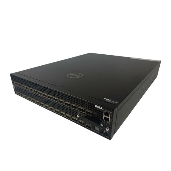
Page 12: Chassis Physical Design
Step Task Remove the small plastic cover from the DC connectors. Ensure that the power source is turned off. Do not attach the DC cable to the DC connectors while the power source is on. Attach the connectors to the PSUs, making sure that the connections are secure. -
Page 13: Power Supplies
The Z9000 is designed to support two hot-swappable power supplies. NOTE: If using a single PSU, you must install a blank plate in the other PSU slot. Dell Force10 recommends using PSU0, if installing only one power supply. WARNING: To prevent electrical shock, make sure the Z9000 is grounded properly. -
Page 14: Install A New Dc Power Supply
CAUTION: Remove the power cable from the modules prior to removing the module itself. Power must not be connected prior to insertion in the chassis. WARNING: Prevent exposure and contact with hazardous voltages. Do not attempt to operate this system with the safety cover removed. CAUTION: Be sure that the DC power source is turned OFF before attaching the cables to the DC connectors on the Z9000. -
Page 15: Installing The Software
Installing the Software Navigating CLI Modes The FTOS prompt changes to indicate the CLI mode. You must move linearly through the command modes, with the exception of the end command which takes you directly to EXEC Privilege mode; the exit command moves you up one command mode level. - Page 16 Step Task Terminal settings on the console port cannot be changed in the software and are set as follows: 9600 baud rate No parity 8 data bits 1 stop bit No flow control Accessing the RJ-45 console port with a DB-9 adapter You can connect to the console using an RJ-45 to RJ-45 rollover cable and an RJ-45 to DB-9 female DTE adapter to a terminal server (for example, PC).
-
Page 17: Default Configuration
Default Configuration A version of the Dell Force10 Operating System (FTOS) is pre-loaded onto the chassis, however the system is not configured when you power up for the first time (except for the default hostname, which is Force10). You must configure the system using the Command Line Interface (CLI). -
Page 18: Access The System Remotely
Access the System Remotely You can configure the system to be accessed remotely by Telnet. The Z-Series has a dedicated management port and a management routing table that is separate from the IP routing table. Step Task Configure an IP address for the management port. Configure a management route with a default gateway. -
Page 19: Configure A Username And Password
DES encryption method. • enable secret is stored in the running/startup configuration in using a stronger, MD5 encryption method. Dell Force10 recommends using the enable secret password. Task Command Syntax Command Mode Create a password to... -
Page 20: Create A Port-Based Vlan
Create a Port-based VLAN The Default VLAN as VLAN 1 is part of the system startup configuration and does not require configuration. To configure a port-based VLAN, you must create the VLAN and then add physical interfaces or port channel (LAG) interfaces to the VLAN. -
Page 21: Assign An Ip Address To A Vlan
Step Task Command Syntax Command Mode Access the interface vlan vlan-id CONFIGURATION INTERFACE VLAN mode of the VLAN to which you want to assign the interface. Configure an interface untagged interface INTERFACE as untagged. This command is available only in VLAN interfaces. - Page 22 Installing the Software...
- Page 24 Printed in the U.S.A. w w w. d e l l . c om | s u p p o r t . d e l l . c om...
Need help?
Do you have a question about the Force10 Z9000 and is the answer not in the manual?
Questions and answers