Dell Force10 S4810P Quick Start Manual
Quick start guide
Hide thumbs
Also See for Force10 S4810P:
- Manual (60 pages) ,
- Configuration manual (1144 pages) ,
- Reference manual (1637 pages)
Table of Contents
Advertisement
Advertisement
Table of Contents

Related Manuals for Dell Force10 S4810P


Summary of Contents for Dell Force10 S4810P
-
Page 1: Quick Start Guide
Dell Force10 S4810 System Quick Start Guide Regulatory Model: S4810P... - Page 3 Dell Force10 S4810 System Quick Start Guide Regulatory Model: S4810P...
-
Page 4: Notes, Cautions, And Warnings
Other trademarks and trade names may be used in this publication to refer to either the entities claiming the marks and names or their products. Dell Inc. disclaims any proprietary interest in trademarks and trade names other than its own. -
Page 5: About This Guide
About this Guide This document is intended as a Quick Start Guide to get new systems up and running and ready for configuration. For complete installation and configuration information, refer to the following documents: Documentation S4810 Hardware installation and power-up Installing the S4810 System instructions Software configuration... - Page 6 About this Guide...
-
Page 7: Installing The Hardware
Installing the S4810 Chassis in a Rack or Cabinet To install the S4810 system, Dell Force10 recommends that you complete the installation procedures in the order presented below. Always handle the system and its components with care. Avoid dropping the S4810 chassis or its field replaceable units. - Page 8 The S4810 is shipped with 1 M4x0.7 screw for attaching a ground cable to the chassis. The cable itself is not included. Dell Force10 recommends a 6AWG one-hole lug, #10 hole size, 63" spacing (not included in shipping) to properly ground the chassis.
- Page 9 Take the (1) M4x0.7 screw from the package. Cut cable to desired length. Cable length must facilitate the proper operation of fault interrupt circuits. Dell Force10 recommends using the shortest cable route allowable. Attach the one-hole lug to the chassis as shown, using the supplied screw with captive internal tooth lock washer.
-
Page 10: Supply Power And Power Up The System
Step Task Insert the optic into the port until it gently snaps into place. NOTE: Both rows of QSFP+ ports require that the 40G optics be inserted with the tabs facing up. Splitting QSFP Ports to SFP+ Ports The S4810 supports splitting a single 40G QSFP port into four 10G SFP+ ports using one of the supported breakout cables (refer to Installing the S4810 System or Release Notes for the S4810 System for a list of supported cables). - Page 11 Dell Force10 recommends re-inspecting your system prior to powering up. Verify that: • The equipment is properly secured to the rack and properly grounded. • The equipment rack is properly mounted and grounded. • The ambient temperature around the unit (which may be higher than the room temperature) is within the limits specified for the S4810.
-
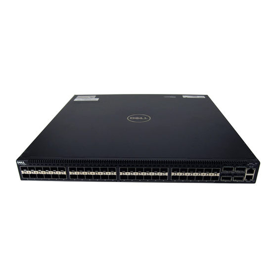
Page 12: Chassis Physical Design
chassis is powered-up; there is no on/off switch. Fans The S4810 comes from the factory with 1 power supply and 2 fan modules installed in the chassis. Both the fan module and the integrated fan-power supply are hot-swappable if a second (redundant) power supply is installed and running. -
Page 13: Environmental Parameters
Parameter Specifications Power Consumption 230 Watts (nominal) 270 Watts (maximum) Environmental Parameters Parameter Specifications Temperature 32° to 104°F (0° to 40°C) -40° to 158°F (-20° to 70°C) Maximum altitude No performance degradation to 10,000 feet (3,048 meters) Relative humidity 10 to 85% non-condensing Shock MIL-STD-810 AC Power Requirements... -
Page 14: Power Supplies
CAUTION: The DC power supply comes with a 6-8inch cord with a snap-in plug that attaches to the DC power supply and screw terminals that attach to the main power. Dell Force10 recommends using a longer cable, to ensure sufficient room. - Page 15 Step Task Take the power supply unit out of the shipping box. Using the grab handle, slide the unit into the power supply bay. Tighten the securing screw on the side of the PSU. Attach power cables. The system powers up as soon as the cables are connected between the power supply and the power source.
- Page 16 Installing the Hardware...
-
Page 17: Installing The Software
Installing the Software Navigating CLI Modes The FTOS prompt changes to indicate the CLI mode. You must move linearly through the command modes, with the exception of the end command which takes you directly to EXEC Privilege mode; the exit command moves you up one command mode level. -
Page 18: Default Configuration
Accessing the RJ-45 Console Port with a DB-9 Adapter You can connect to the console using an RJ-45 to DB-9 adapter along with the RJ-45 rollover cable if the DTE has a DB-9 interface. Table 2-1 lists the pin assignments. Table 2-1. -
Page 19: Configure A Host Name
Step Task Command Syntax Command Mode Place the interface in switchport INTERFACE Layer 2 (switching) mode. To view the interfaces in Layer 2 mode, use the show interfaces switchport command in the EXEC mode. Configure a Host Name The host name appears in the prompt. The default host name is force10. •... -
Page 20: Configure A Management Route
Step Task Command Syntax Command Mode Enter INTERFACE interface ManagementEthernet CONFIGURATION mode for the slot/port Management port. Assign an IP address ip address ip-address/mask INTERFACE to the interface. Enable the interface. no shutdown INTERFACE Configure a Management Route Define a path from the system to the network from which you are accessing the system remotely. -
Page 21: Configure The Enable Password
DES encryption method. • enable secret is stored in the running/startup configuration in using a stronger, MD5 encryption method. Dell Force10 recommends using the enable secret password. Task Command Syntax Command Mode Create a password to... -
Page 22: Assign Interfaces To A Vlan
Assign Interfaces to a VLAN Only interfaces in Layer 2 mode can be assigned to a VLAN using the tagged and untagged commands. Use the switchport command to place an interface in Layer 2 mode. These Layer 2 interfaces can further be designated as tagged or untagged. When an interface is placed in Layer 2 mode by the switchport command, the interface is automatically designated untagged and placed in the Default VLAN. -
Page 23: Assign An Ip Address To A Vlan
Step Task Command Syntax Command Mode Configure an interface untagged interface INTERFACE as untagged. This command is available only in VLAN interfaces. Assign an IP address to a VLAN VLANs are a Layer 2 feature. For two physical interfaces on different VLANs to communicate, you must assign an IP address to the VLANs to route traffic between the two interfaces. - Page 24 Installing the Software...
- Page 26 Printed in the U.S.A. w w w. d e l l . c om | s u p p o r t . d e l l . c om...
Need help?
Do you have a question about the Force10 S4810P and is the answer not in the manual?
Questions and answers