Dell Force10 S4810P Manual
Installing the s4820t system
Hide thumbs
Also See for Force10 S4810P:
- Quick start manual (27 pages) ,
- Configuration manual (1144 pages) ,
- Reference manual (1637 pages)
Table of Contents
Advertisement
Quick Links
Advertisement
Table of Contents

Related Manuals for Dell Force10 S4810P


Summary of Contents for Dell Force10 S4810P
- Page 1 Installing the S4820T System Publication Date: January 2013...
- Page 2 © 2013 Dell Force10. All rights reserved. Reproduction of these materials in any manner whatsoever without the written permission of Dell Inc. is strictly forbidden. Trademarks used in this text: Dell™, the DELL logo, Dell Precision™, OptiPlex™, Latitude™, PowerEdge™, PowerVault™, ®...
-
Page 3: Table Of Contents
Rack Mounting Safety Considerations....... . 23 Installing the Dell ReadyRails System ....... . 24 Two-post Flush-mount Configuration. - Page 4 Removing QSFP+ Optics......... . 31 Splitting QSFP+ Ports to SFP+ or RJ-45 Ports .
- Page 5 Korean Certification of Compliance ........51 Safety Standards and Compliance Agency Certifications ....51 Electromagnetic Compatibility (EMC) .
-
Page 7: About This Guide
NOTE: User port stacking requires Dell Force10 Operating System (FTOS) version 8.3.19.0 NOTE: For information about upgrading the S4820T system, refer to the FTOS Release Notes for the S4820T System. If you have any questions regarding FTOS versions and system upgrades, contact Dell Force10 Technical Support. -
Page 8: Related Publications
Table 1-1. Information Symbols (continued) Symbol Warning Description Warning This symbol informs you about hardware handling that could result in injury. This symbol informs you that you must take electrostatic precautions when handling the device. Warning Related Publications For more information about the S4820T system, refer to the following documents: •... -
Page 9: The S4820T Switch
The S4820T Switch This chapter contains general features, capabilities, and physical configurations supported by the S4820T. This chapter also contains a lists of optical and copper connectors that are supported by the S4820T, as well as a list of optional parts available for purchase. Introduction S4820T is a top-of-rack (ToR) switch/router product for copper connections to 10Gbps servers and 40Gbps optical uplinks to the 40Gbps switching fabric in the core. -
Page 10: Features
In a data center network, the S4820T switch provides converged network support and inter-operates with Dell and third-party ToR devices. The switch supports data center bridging (DCB) features and optimizes connectivity between servers and storage devices using Fibre Channel over Ethernet (FCoE) and Internet Small Computer System Interface (iSCSI) links. -
Page 11: Chassis Ports
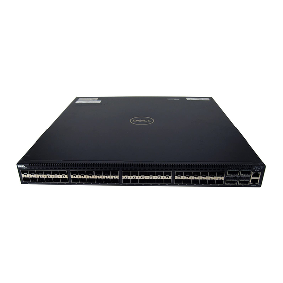
Chassis Ports The following is a list of the standard ports located on each S4820T chassis: • Serial RS-232 port (RJ-45 type) • Out of band Ethernet management port (RJ-45 type) • Forty-eight 1/10Gbps RJ-45 ports • Four 40Gbps QSFP+ ports for four 40Gbps transceivers •... - Page 12 Table 2-1. System LED Displays Feature Detailed Description Comment System LED • Solid blue – Normal Operation I/O side • Blinking blue – Booting • Solid red – Critical system error • Blinking red – Non-critical system error (fan fail, power supply fail) TEMP LED •...
- Page 13 Table 2-4. Out of Band Ethernet Port LEDs Feature Detailed Description Link LED • Off – No Link • Solid green – Link on 1Gbps speed • Solid Amber – Link on 100M or 10M speeds Activity LED • Off – No Link •...
-
Page 14: Basic Installation Requirements
Basic Installation Requirements Detailed installation instructions for the S4820T are provided in Chapter 3, Site Location and Preparation Chapter 4, Installing the S4820T, however, the following, is an initial list of components required for a successful installation of the S4820T: •... -
Page 15: Orderable S4820T Components
Orderable S4820T Components You can order the S4820T system in several different configurations. Also, you can order optional modules and optics separately. The Following is a list of different configurations, modules: Table 2-5. Supported Hardware Components Hardware S4820T AC Normal Airflow: 48 port 10G RJ-45 ports with 4 QSFP+ 40G ports, 1 AC power supply and 2 fan subsystems (airflow from I/O side to power supply side) S4820T AC Reverse Airflow: 48 port 10G RJ-45 ports with 4 QSFP+ 40G ports, 1 AC power supply and 2 fan subsystems (airflow from power supply side to I/O side) - Page 16 The S4820T Switch...
-
Page 17: Site Location And Preparation
Site Location and Preparation The S4820T is suitable for installation as part of a Common Bond Network (CBN). It can be installed in: • Network telecommunication facilities • Data centers • Other locations where the National Electric Code (NEC) applies This chapter contains the following sections regarding where and how the S4820T should be installed: •... -
Page 18: Site Selection
Site Selection Dell Force10 Networks’ equipment is intended for installation in restricted access areas. A restricted access area is one in which access can only be gained by service personnel through the use of a special tool, lock, key or other means of security and access is controlled by the authority responsible for the location. -
Page 19: Fan Combinations
Storing Components If you do not install your S4820T and components immediately, Dell Force10 recommends properly storing the system and all optional components until you are ready to install them. - Page 20 • Store on a dry surface or floor, away from direct sunlight, heat, and air conditioning ducts. • Store in a dust-free environment. WARNING: Electrostatic discharge (ESD) damage can occur when components are mishandled. Always wear an ESD-preventive wrist or heel ground strap when handling the S4820T and its accessories. After you remove the original packaging, place the S4820T and its components on an antistatic surface.
-
Page 21: Installing The S4820T
Installing the S4820T To install the S4820T system, Dell Force10 recommends completing the installation procedures in the order presented in this chapter. Always handle the S4820T and its components with care. Avoid dropping the system or its Field Replaceable Units (FRUs). -
Page 22: Unpacking Steps
• At least one PSU • If an AC switch, at least one AC power cord (country/region specific) • If a DC switch, at least one DC power cable • Getting Started Guide • Safety and Regulatory Information • Warranty and Support Information •... -
Page 23: Installing Rack Or Cabinet Hardware
You may either place the switch on the rack shelf or mount the switch directly into a 19" wide, EIA-310- E- compliant rack (four-post, two-post, or threaded methods). The Dell ReadyRails™ system is provided for one 1U front-rack, and two-post installations. The ReadyRails system includes two separately packaged rail assemblies and two rails that are shipped attached to the sides of the switch. -
Page 24: Installing The Dell Readyrails System
Installing the Dell ReadyRails System The ReadyRails rack mounting system is provided to easily configure your rack for installation of your S4820T switch. The ReadyRails system can be installed using the 1U tool-less method or one of three possible 1U tooled methods (two-post flush mount, two-post center mount, or four-post threaded). -
Page 25: Two-Post Flush-Mount Configuration
Two-post Flush-mount Configuration For this configuration, you must remove the castings from the front side of each ReadyRails assembly. Refer to Figure 4-2, step 1. Use a Torx driver to remove the two screws from each front flange ear (on the switch side of the rail) and remove each casting. Retain the castings for future rack requirements. -
Page 26: Two-Post Center-Mount Configuration
Two-post Center-mount Configuration Slide the plunger bracket rearward until it clicks into place and secure the bracket to the front post flange with two user-supplied screws. Refer to Figure 4-3, step 1. Figure 4-3. Two-post Center-mount Configuration Slide the back bracket towards the post and secure it to the post flange with two user-supplied screws. -
Page 27: Four-Post Threaded Configuration
Four-post Threaded Configuration For this configuration, you must remove the flange ear castings from each end of the ReadyRails assemblies. Use a Torx driver to remove the two screws from each flange ear and remove each casting. Refer to Figure 4-4, step 1. -
Page 28: Installing The S4820T Switch
Use a single M4x0.7 screw to attach the ground cable to the chassis. The cable itself is not included with the S4820T. To properly ground the chassis, Dell Force10 recommends using a 6AWG one-hole lug, #10 hole size, 63" spacing (not included in shipping). The one-hole lug must be a UL recognized, crimp-type lug. -
Page 29: Installing An Ac Or Dc Power Supply
PSU to I/O). Two PSUs are required for full redundancy, but the system will operate with a single PSU. NOTE: If you use a single PSU, you must install a blank plate in the other PSU slot. Dell Force10 recommends using power supply 1 (PSU1) as the blank plate slot. - Page 30 Remove the PSU slot cover from the S4820T (PSU side of switch), either of the two PSU slots may be selected. Remove the PSU from the electrostatic bag. Insert the PSU into the switch PSU slot (PSU exposed PCB edge connector should be inserted first). The PSU slot is keyed such that the PSU can only be fully inserted in one orientation.
-
Page 31: Installing Qsfp+ Optics
Installing QSFP+ Optics The S4820T has four QSFP+ optical ports. For supported optics, refer to http:// www.force10networks.com/products/specifications.asp. WARNING: ESD damage can occur if components are mishandled. Always wear an ESD-preventive wrist or heel ground strap when handling the S4820T and its components. WARNING: When working with optical fibers, follow all warning labels and always wear eye protection. -
Page 32: Powering Up The S4820T Switch
Powering Up the S4820T Switch Supply power to the S4820T after it is mounted in a rack or cabinet. Dell Force10 recommends re-inspecting your system prior to powering up. Verify that: • Equipment is properly secured to the rack and properly grounded. -
Page 33: Connecting The Stacking Ports (Optional)
You can connect the systems while they are powered down or up. Stacking ports are bi-directional. The S4820T supports stacking in either a ring or a cascade topology (Figure 4-8). To provide redundant connectivity, Dell Force10 recommends using the ring topology when stacking S4820T systems. Installing the S4820T... -
Page 34: Connect Two S4820T Systems
48 56 48 56 Connect Two S4820T Systems To provide backup connectivity and increased data transfer between the systems, Dell Force10 recommends inserting an additional cable between the two units, in a second stacking port, as shown in Figure 4-9. -
Page 35: Connect Three S4820T Systems
Chassis 2 Chassis 1 Connect Three S4820T Systems To provide backup connectivity and increased data transfer between the systems, Dell Force10 recommends inserting an additional cable between the two units, in a second stacking port, as shown in Figure 4-10. -
Page 36: Hot-Swapping Units In A Stack
Figure 4-10. Three S4820Ts Connected in a Ring Chassis 3 Chassis 2 Chassis 1 Hot-Swapping Units in a Stack You can add, remove, or swap S4820T units in an existing stack. The units in the stack and the new units can be already powered up or powered down. - Page 37 For more information about removing a unit from a stack and other stacking commands, refer to the Stacking chapter in the FTOS Configuration Guide for the S4820T System and the Stacking Commands chapter in the FTOS Command Line Reference Guide for the S4820T System. Installing the S4820T...
- Page 38 Installing the S4820T...
-
Page 39: Power Supplies
Two PSUs are required for full redundancy, but the system will operate with a single PSU. NOTE: If you use a single PSU, you must install a blank plate in the other PSU slot. Dell Force10 recommends using power supply 1 (PSU1) as the blank plate slot. -
Page 40: Installing An Ac Or Dc Power Supply
NOTE: The PSU slides into the slot smoothly. Do not force a PSU into a slot as this may damage the PSU or the S4820T chassis. NOTE: If you use a single PSU, you must install a blank plate in the other PSU slot. Dell Force10 recommends using power supply 1 (PSU1) as the blank plate slot. -
Page 41: Connecting A Dc Power Supply To The Power Source
To replace an AC or DC power supply, follow these steps: Step Task Disconnect the power cable from the PSU. Loosen the securing screws on the PSU with a screwdriver. Ensure that the PSU loose and can be easily removed. Use the grab handle to slide the PSU out of the power supply bay. -
Page 42: Removing Power Connector From An S4820T Dc Power Supply
To connect a S4820T DC PSU to the site’s DC power source, follow these steps: Step Task Strip 1/2” of insulation from each of the power connector’s wires (red and black, See Figure 5-2). Insert each of the power connector’s bare wire lengths into the wiring block (See Figure 5-2). -
Page 43: Fans
Fans The S4820T comes from the factory with one power supply unit (PSU) and two fan modules installed in the chassis (see Figure 6-1). The fan modules and the integrated fan-power supply are hot-swappable. NOTE: To run the system, both slots must have operating fan units. If a module is not installed in each slot (either as part of the PSU or as an independent fan module), the system shuts down in one minute. -
Page 44: Install A Fan Module
Install a Fan Module CAUTION: DO NOT mix airflow directions. Both fans must use the same airflow direction (reverse or normal). If the airflows are mismatched, an error message appears and the system shuts down. 00:02:19:%S4820T:0%CHMGR-2-PSU_TYPE_AIRFLOW_MISMATCH: Mismatching PSU airflow detected. Unit 0 shall get shutdown in next 60 seconds if mismatch not rectified. -
Page 45: Management Ports
Management Ports Besides the 10 Gigabit and 40 Gigabit switch ports, the S4820T provides several ports for management and storage. Accessing the RJ-45 Console Port (RS-232) NOTE: Before starting this procedure, be sure that your PC has a 9-pin serial port and that you have a terminal emulation program already installed and running on the PC. -
Page 46: Default Configuration
Default Configuration A version of FTOS is pre-loaded onto the S4820T switch; however, the switch is not configured when you power it up for the first time (except for the default host name, which is ). You must configure FTOS the switch using the CLI. -
Page 47: Specifications
Specifications This chapter contains the following sections: • Chassis Physical Design • Environmental Parameters • Power Requirements • IEEE Standards • Agency Compliance Caution: Operate the product at an ambient temperature not higher than 113°C. Lithium Battery Caution: There is a danger of explosion if the battery is incorrectly replaced. Replace only with same or equivalent type. -
Page 48: Power Requirements
Power Requirements The tables below represents the PSU’s capabilities and does not represent the S4820T’s operation. AC Input Specification Parameter Specifications Power supply 100–240 VAC 50/60 Hz Maximum current draw per system 5.8 A @ 398.02watts/100vac 2.9 A @ 398.02watts/200vac Maximum power consumption 460 Watts (AC) Maximum power consumption... -
Page 49: Agency Compliance
• 802.3ad Link Aggregation with LACP • 802.3ae 10 Gigabit Ethernet (10GBASE-X) • 802.3ba 40 Gigabit Ethernet (40GBase-SR4, 40GBase-CR4) on optical ports • 802.3u Fast Ethernet (100BASE-TX) • 802.3x Flow Control • 802.3z Gigabit Ethernet (1000BASE-X) • ANSI/TIA-1057 (LLDP-MED) • Force10 (PVST+) •... -
Page 50: Canadian Department Of Communication Statement
Properly shielded and grounded cables and connectors must be used in order to meet FCC emission limits. Dell Force10 is not responsible for any radio or television interference caused by using other than recommended cables and connectors or by unauthorized changes or modifications in the equipment. -
Page 51: Japan: Vcci Compliance For Class A Equipment
Information Technology Equipment (VCCI). If this equipment is used in a domestic environment, radio disturbance may arise. When such trouble occurs, the user may be required to take corrective actions. WARNING: Use the AC power cords with Dell Force10 equipment only. Do not use Dell Force10 AC power cords with any unauthorized hardware. -
Page 52: Electromagnetic Compatibility (Emc)
Force10 encourages owners of information technology (IT) equipment to responsibly recycle their equipment when it is no longer needed. Dell Force10 offers a variety of product return programs and services in several countries to assist equipment owners in recycling their IT products. - Page 53 EEE on the environment and human health due to the potential presence of hazardous substances in EEE. Dell Force10 products, which fall within the scope of the WEEE, are labeled with the crossed-out wheelie-bin symbol, as shown above, as required by WEEE.
- Page 54 Specifications...
-
Page 55: Technical Support
Requesting a Hardware Replacement The iSupport Website iSupport provides a range of documents and tools to assist you with effectively using Dell Force10 equipment and mitigating the impact of network outages. Through iSupport you can obtain technical information regarding Dell Force10 products, access to software upgrades and patches, and open and manage your Technical Assistance Center (TAC) cases. -
Page 56: Contacting The Technical Assistance Center
Contacting the Technical Assistance Center How to Contact Dell Force10 Log in to iSupport at http://www.force10networks.com/support/ and select the Service Request tab. Information to Submit When • Your name, company name, phone number, and E-mail address Opening a Support Case •... -
Page 57: Requesting A Hardware Replacement
• Using the Create Service Request form on the iSupport page (see Contacting the Technical Assistance Center). • Contacting Dell Force10 directly by E-mail or by phone (see Contacting the Technical Assistance Center). Provide the following information when using E-mail or phone: •... - Page 58 Technical Support...
- Page 60 Printed in the U.S.A. w w w. d e l l . c o m | s u p p o r t . d e l l . c o m...
Need help?
Do you have a question about the Force10 S4810P and is the answer not in the manual?
Questions and answers