Table of Contents
Advertisement
Advertisement
Table of Contents

Related Manuals for Haier HSU24VCK


Summary of Contents for Haier HSU24VCK
- Page 1 Order No.AC1101S008V0 ON/OFF EK-Series Model No.HSU24VCK 2011...
-
Page 2: Table Of Contents
HSU24VCK-SM Table of Contents 1. Features..................... 1 2. Introduction ....................2 3. Specifications .................... 7 4. Printed circuit board connector wiring diagram ........9 5. Functions and control ................10 5.1 Main functions and control specification ..........10 5.2 Value of thermistor ................... 13 6. -
Page 3: Features
HSU24VCK-SM Table of Contents... -
Page 4: Introduction
HSU24VCK-SM Table of Contents 2. Introduction 2.1 Safety Cautions Be sure to read the following safety cautions before conducting repair work. The caution items are classified into “Warning” and “Caution”. The “Warning” items are especially important since they can lead to death or serious injury if they are not followed closely. The “Caution” items can also lead to serious accidents under some conditions if they are not followed. -
Page 5: Cautions Regarding Products After Repair
HSU24VCK-SM Introduction Warning Do not repair the electrical components with wet hands. Working on the equipment with wet hands can cause an electrical shock. Do not clean the air conditioner by splashing water. Washing the unit with water can cause an electrical shock. - Page 6 HSU24VCK-SM Introduction Warning Be sure to use an exclusive power circuit for the equipment, and follow the technical standards related to the electrical equipment, the internal wiring regulations and the instruction manual for installation when conducting electrical work. Insufficient power circuit capacity and improper electrical work can cause an electrical shock or fire.
-
Page 7: Inspection After Repair
HSU24VCK-SM Introduction 2.1.3 Inspection after Repair Warning Check to make sure that the power cable plug is not dirty or loose, then insert the plug into a power outlet all the way. If the plug has dust or loose connection, it can cause an electrical shock or fire. -
Page 8: Using Icons
HSU24VCK-SM Introduction 2.1.4 Using Icons Icons are used to attract the attention of the reader to specific information. The meaning of each icon is described in the table below: 2.1.5 Using Icons List Icon Type of Information Description A “note” provides information that is not indispensable, but may... -
Page 9: Specifications
HSU24VCK-SM HSU24VCK Model Cooling 6.4/6.2 Btu/h Capacity Rated 22000/21400 5504/5332 Kcal/h POWER SUPPLY NOMINAL Phase DISTRIBUTION Frequency SYSTEM VO LTAGE Voltage 230/208V Moisture Removal Pints/hr 8.6/9.3 Running Current(Rated) Power Consumption Rated 1950/1900 BTU/(h.W) 11.28/11.26 EER Rated inches Liquid Piping Connections... - Page 10 HSU24VCK-SM Outdoor Unit HSU24VCK Casing Color lvory white Type Hermetic motor compressor Model Motor Output 1480 Compressor a 68HES-H or equivalent Oil Type Oil Charge pints Model R410A Refrigerant pounds Charge 53.3 m³/min Air Flow Rate (H/L) 1881.5 Type Axial fan...
-
Page 11: Printed Circuit Board Connector Wiring Diagram
HSU24VCK-SM Connector Wiring Diagram 4.Printed Circuit Board Connector Wiring Diagram 4.1 Indoor unit Connectors Indoor PCB 1)CN26 connector for DC fan motor. 2)CN11 connector for step motor. 3)CN32-2 connector for receiver display. 4)CN54 connector for power line N. 5)CN1 connector for ambient temp. sensor and piping temp.sensor. -
Page 12: Functions And Control
HSU24VCK-SM Functions and Control 5 Functions and control 5.1 main functions and control specifications Including brief introduction to air conditioners of series models and electric control function. 5.1.1 Automatic running (1) Single cold automatic run mode: After entering into this mode, the main control “MCU” determines the corresponding work pattern according to the indoor temperature so as to maintain the preset temperature (the preset temperature is 78°... - Page 13 HSU24VCK-SM Functions and Control (1)High temperature expiration prevention:When the temp.of coil pipe is above 161 °F,compre- ssor andoutlet air stop running 10 seconds later, and inlet air runs as the temp. sensor is off. When compressorstands by for 3 minute and the temp. of coil pipe is below 149 °F, the unit can be started again.
- Page 14 HSU24VCK-SM Functions and Control hours and then close. 5.1.6.2 In heating mode, the temp. setting decrease 3 F one hour after start up. After another hour the temp. setting decrease by more 3 F. After 3 hours the temp. setting rise by 1 F and then run continuously for another 3 hours and then close 5.1.6.3 If the wind speed is set to high before going to bed, the wind speed become medium after...
-
Page 15: Value Of Thermistor
HSU24VCK-SM Functions and Control function of power on is optional. (In auto, heating, cooling, or defrosting status, press the “ ” button to enter additional options when cycle dispay to will flash and then press quickly press and then press rapidly 10 times within 6 seconds, and the auto recovery function of power on can be set on/off. - Page 16 HSU24VCK-SM Functions and Control 123.4597 113.7009 104.5852 -1.49 1.39 116.4577 107.4349 98.9897 -1.47 1.38 109.8953 101.5523 93.7278 -1.45 1.36 103.7422 96.0274 88.7774 -1.43 1.34 97.9708 90.8365 84.1185 -1.40 1.32 92.5551 85.9574 79.7322 -1.38 1.30 87.4712 81.3697 75.6011 -1.36 1.29 82.6970 77.0544...
- Page 17 HSU24VCK-SM Functions and Control 14.0599 13.3650 12.6889 -1.20 1.16 13.4786 12.7957 12.1325 -1.23 1.20 12.9244 12.2537 11.6035 -1.27 1.24 12.3960 11.7375 11.1004 -1.31 1.27 11.8921 11.2459 10.6218 -1.35 1.31 11.4113 10.7775 10.1665 -1.39 1.34 10.9526 10.3311 9.7330 -1.43 1.38 10.5147 9.9056...
- Page 18 HSU24VCK-SM Functions and Control 2.7845 2.5176 2.2735 -3.12 2.86 2.6931 2.4324 2.1943 -3.17 2.90 2.6050 2.3505 2.1182 -3.22 2.94 2.5203 2.2717 2.0451 -3.28 2.99 2.4388 2.1960 1.9749 -3.33 3.03 2.3602 2.1231 1.9075 -3.38 3.07 2.2846 2.0530 1.8426 -3.43 3.12 2.2118 1.9856...
- Page 19 HSU24VCK-SM Functions and Control Pipe Sensor R25 =10KΩ±3% B25 /50 =3700K±3% Temp.(( )) Max.(KΩ) Normal(KΩ) Min.(KΩ) Tolerance( ) 165.2170 147.9497 132.3678 -1.94 1.75 155.5754 139.5600 125.0806 -1.93 1.74 146.5609 131.7022 118.2434 -1.91 1.73 138.1285 124.3392 111.8256 -1.89 1.71 130.2371 117.4366 105.7989...
- Page 20 HSU24VCK-SM Functions and Control 24.1432 22.8656 21.6361 -1.20 1.16 23.0284 21.8398 20.6939 -1.18 1.14 21.9714 20.8659 19.7982 -1.15 1.12 20.9688 19.9409 18.9463 -1.13 1.09 20.0176 19.0621 18.1358 -1.11 1.07 19.1149 18.2270 17.3646 -1.08 1.05 18.2580 17.4331 16.6305 -1.06 1.03 17.4442 16.6782...
- Page 21 HSU24VCK-SM Functions and Control 4.2026 3.9686 3.7443 -1.65 1.59 4.0588 3.8287 3.6084 -1.70 1.62 3.9206 3.6943 3.4780 -1.74 1.66 3.7878 3.5654 3.3531 -1.78 1.70 3.6601 3.4416 3.2332 -1.82 1.74 3.5374 3.3227 3.1183 -1.87 1.78 3.4195 3.2085 3.0079 -1.91 1.82 3.3060 3.0989...
- Page 22 HSU24VCK-SM Functions and Control 1.0910 0.9882 0.8942 -3.69 3.37 1.0607 0.9599 0.8679 -3.74 3.42 1.0314 0.9326 0.8424 -3.80 3.46 1.0030 0.9061 0.8179 -3.85 3.51 0.9756 0.8806 0.7941 -3.90 3.55 0.9490 0.8558 0.7711 -3.96 3.60 0.9232 0.8319 0.7489 -4.01 3.64 0.8983 0.8088...
-
Page 23: System Configuration
HSU24VCK-SM 6. System Configuration 6.1 System Configuration After the installation and test operation of the room air conditioner have been completed, it should be operated and handled as described below. Every user would like to know the correct method of operation of the room air conditioner, to check if it is capable of cooling (or heating) well, and to know a clever method of using it.In order to... -
Page 24: Instruction
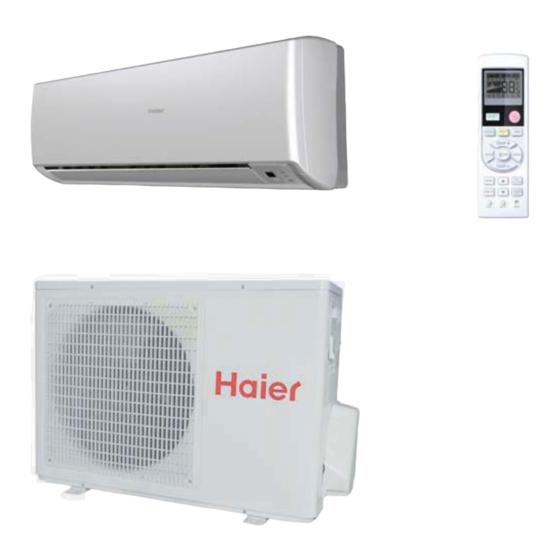
HSU24VCK-SM Parts and Functions Indoor Unit Remote controller 7.TEMP display Additional functions display Operation mode QUITE SLEEP HEALTH POWER Remote controller 9. QUIET button 10. COOL button 11. AUTO button 12. FAN button 13. TIMER button 14. HEALTH button 15. LOCK button Used to lock buttons and LCD display 16. -
Page 25: Emergency Operation
HSU24VCK-SM Operation Base Operation Emergency operation and test operation Emergency Operation: Use this operation only when the remote controller is defective or lost, and with function of emergency running, air conditoner Remote controller can run automatically for a while. When the emergency operation switch is pressed, the unit beeps once, which means the start of this operation. -
Page 26: Sleep Operation
HSU24VCK-SM Operation Sleep Operation 4.Set the wind speed change when sleeping If the wind speed is high or middle before setting for the Press button to enter additional options, when sleep, set for lowing the wind speed after sleeping. cycle display to will flash. -
Page 27: Healthy Airflow Operation
HSU24VCK-SM Operation Timer On/Off On-Off Operation Healthy airflow Operation 1.After unit starts, select your desired operation mode. 1.Press to starting Setting the comfort work conditions. 2.Press TIMER button to change TIMER mode. Every time the button is pressed, display changes as follows: 2.The setting of healthy airflow function... -
Page 28: Replacement Of Air Purifying Filter
HSU24VCK-SM Maintenance For Smart Use of The Air Conditioner Remote Controller Indoor Body Setting of proper room Do not block the air inlet temperature or outlet Proper wipe the air conditioner by using a temperature soft and dry cloth.For serious stains,... - Page 29 HSU24VCK-SM Table of Contents Cautions WARNING This system should be installed by a qualified HVAC professional. Do not attempt to install the air conditioner by yourself because improper works may cause fire, water leakage, personal injury or cleath. WARNING Check proper...
-
Page 30: Trouble Shooting
HSU24VCK-SM Trouble shooting Cautions Before asking for service, check the following Do not obstruct or cover the ventilation grille of the air first. or any other things into the conditoner.Do not put fingers inlet/outlet and swing louver. Cause or check points... -
Page 31: Service Diagnosis
HSU24VCK-SM Codes and Description 7.Codes and Description 7.1.Problem Symptoms and Measures Symptom Check Item Details of Measure Check to make sure that the rated voltage is Check the power supply. supplied. None of the Check to make sure that the indoor PCB is... - Page 32 HSU24VCK-SM Codes and Description whether terminal CN8 Pull out the terminals on the indoor mainboard and indoor PCB contact well? reinsert them Pull the sensor out of the mainboard Measure the value of resistance Between its two jumpers Measure the temperature at the room temperature sensing head.
- Page 33 HSU24VCK-SM Codes and Description Turn off power supply and rotate fan by hand Does fan rotate Replace fan motor smoothly? Turn power ON and operate fan Turn off power supply and disconnect fan Does it rotate? motor connector,then turn power ON...
-
Page 34: Capacity Diagrams And Curves Diagrams
HSU24VCK-SM 8.1 Cooling Capacity-temperature Curves HSU24VCK Performance Curves Capacity-temp.Curves indoor temp cooling temp.(humidity)40% DB/WB 67/50 20460 20020 19360 18700 18040 17160 15840 13860 67/57 22000 21560 21120 20460 19580 18700 17380 15840 67/62 23760 23320 22660 21780 21120 20460 19140 17600... - Page 35 HSU24VCK-SM 8.2 Cooling Power Consumption Value-temperature Curves HSU24VCK Performance Curves Power Consumption Value-temperature Curves indoor temp cooling temp.(humidity)40% DB/WB 67/50 1365 1424 1482 1560 1619 1677 1794 1872 67/57 1404 1482 1560 1638 1677 1755 1853 2048 67/62 1482 1541...
-
Page 36: Installations
HSU24VCK-SM 9. Installation Preparation Selection of Installation Place Necessary Tools for Installation Indoor Unit - Select a plocation that is Torque wrench Hammer (17mm,22mm,26mm) Nipper Robust not causing vibration, where the body can be supported sufficiently. Hacksaw Pipe cutter Not affected by heat or steam generated in the vicinity, where inlet and outlet of the... -
Page 37: Indoor Unit
HSU24VCK-SM 1. Insert the drain hose into the dent of heat insulation materials of indoor unit. Accessory parts 2. Insert the indoor/outdoor electric cable from backside of indoor unit, and pull it out on the front side, then connect them. -
Page 38: Outdoor Unit
HSU24VCK-SM Ensure that on dirt or debris enters the pipe. The standard pipe length is 7m(27 9/16) . If it is over 7m(27 9/16), the function of the unit will be affected. If the pipe has to be lengthened, the refrigerant should be charged, according to 50 g /m(0.045oz/inch). - Page 39 HSU24VCK-SM No gas leakage? On Drainage In case of gas leakage, tighten parts of pipe connection. If leakage stops, Please install the drain hose so as to be downward slope without fail. then proceed step 6. If leak continues, remove the refrigerant used for the Please don’t do the drainage as shown below.
-
Page 40: Wiring Diagrams
HSU24VCK-SM Wiring Diagrams 10. Wiring Diagrams 10.1 Indoor 10.2 Outdoor DomesticAirConditioner... -
Page 41: Circuit Diagram
HSU24VCK-SM Wiring Diagrams NOTE: 1.The parts are optional. 2.Some types may not have the dotted lines. marked with 10.3 CIRCUIT DIAGRAM P1 2SA1037AK emergency switch R5F212A8SNFA CN48 B2B-XH-A-R TO display CN 32- 2 M ODE P4_5/INT0 TJC8-02 0.001UF TJC8-02 0.1UF... - Page 42 HSU24VCK-SM Wiring Diagrams 1A-800V-500ns-FR106 10Ω-1/4W 1.5K-1/4W SCK-4R72 H-25*15 BCK-6-FE1901 18V-1W-1N4746A 1.5A-7805 10uF-25V-105 3A-200V-ER302 +12V 10Ω-1/4W FUSE1 TVR14561* 1N5399 1A-800V-500ns-FR106 0.1uF 0.1uF T3.15A/250VAC 1000uF-35V-105 470uF-16V 220VAC~/50HZ 1N5399 10Ω-1/4W 32mH-0.35A-LB 2271 1N5399 12V-1W-1N4742A ICE2A265 0.1uF/275V TLP421 1N5399 1Ω-1/2W 2.2nF/250V 2.2nF/250V RLS4148 IC10...
- Page 43 HSU24VCK-SM 10.4 Outdoor Unit...
- Page 44 HSU24VCK-SM...
- Page 45 HSU24VCK-SM 1147...
- Page 46 HSU24VCK-SM...
-
Page 47: Description Of Coding Rules Of Unit Model
HSU24VCK-SM The series number C-cooling only Applicable voltage:V(230/208V) 24000BTU/h) - Page 48 HSU24VCK-SM The end Sincere Forever Haier Group Zhao Ni Guo Liang Yang Bifei 86 532 88936935 Wu Hongjin...
Need help?
Do you have a question about the HSU24VCK and is the answer not in the manual?
Questions and answers