
Related Manuals for Haier HSU24VHG(DB)-G&W


Summary of Contents for Haier HSU24VHG(DB)-G&W
-
Page 1: Service Manual
SERVICE MANUAL Order No.AC1108S003V0 Wall mounted Type DC Inverter EK-Series Model No . HSU24VHG(DB)-G&W indoor unit and remote controller outdoor unit 2012... -
Page 2: Table Of Contents
Table of Contents Table of Contents 1. Introduction ………………………………………………………………………………….. 2. List of Functions …………………………………………………………………………….. 3. Specifications ……………………………………………………………………………….. 4. Printed Circuit Board ConnectorWiring Diagram …………………………………….. 5. Functions and Control ………………..………………………..…………….………..5.1 Main functions and control specifications of indoor unit …….………...…………. 5.2 Main functions and control specifications of outdoor unit ……………..……………… 5.3 Value of Thermistor …………………………………....………..……………………. -
Page 3: Introduction
Introduction 1. Introduction 1.1 Safety Cautions Be sure to read the following safety cautions before conducting repair work. The caution items are classified into “Warning” and “Caution”. The “Warning” items are especially important since they can lead to death or serious injury if they are not followed closely. The “Caution” items can also lead to serious accidents under some conditions if they are not followed. -
Page 4: Cautions Regarding Products After Repair
Introduction Warning Do not repair the electrical components with wet hands. Working on the equipment with wet hands can cause an electrical shock. Do not clean the air conditioner by splashing water. Washing the unit with water can cause an electrical shock. - Page 5 Introduction Warning Be sure to use an exclusive power circuit for the equipment, and follow the technical standards related to the electrical equipment, the internal wiring regulations and the instruction manual for installation when conducting electrical work. Insufficient power circuit capacity and improper electrical work can cause an electrical shock or fire. Be sure to use the specified cable to connect between the indoor and outdoor units.
-
Page 6: Inspection After Repair
Introduction Caution Installation of a leakage breaker is necessary in some cases depending on the conditions of the installation site, to prevent electrical shocks. Do not install the equipment in a place where there is a possibility of combustible gas leaks. If a combustible gas leaks and remains around the unit, it can cause a fire. - Page 7 Introduction Caution Check to see if the parts and wires are mounted and connected properly, and if the connections at the soldered or crimped terminals are secure. Improper installation and connections can cause excessive heat generation, fire or an electrical shock. If the installation platform or frame has corroded, replace it.
- Page 8 Functions Category HSU24VHG(DB)-G&W Healthy negative ion make your room full of an abundance natural negative ions. Avoid the child's wrong operation on the remote controller Child lock The 3D airflow is able to deliver the airflow horizontally and vertically. 3D air flow 24Hour timer Use the timer function to set on,or off,or from on to off,or from off to on The panel is easy to wash and the airflow vents can be detached easily...
- Page 9 HSU24VHG(DB)-G&W 2.0~6.9~7.4 2.5~7.3~7.7 6800~23600~25200 8500~25000~26200 1720~5975~6364 2150~6330~6622 10.2 540~2120~2660 640~2230~2770 11.1 11.39 BTU/(h.W) inches inches inches 0.63 inches 38.74 inches 23.23 inches 15.5 18.3 18.5 15.6 11.7 12.7 0.15 0.15 inches 13X45X10 15X49X14 inches 47/44/41...
- Page 10 HSU-24HEG03/R2(DB) C-6RVN103H0T 1000 FV50BX pints 0.62 R410a pounds 48.3 48.3 1075 1075 10.2 2230 2120 inches 29X34X12 inches 32X39X17...
-
Page 11: Printed Circuit Board Connectorwiring Diagram
Connector Wiring Diagram 4.Printed Circuit Board Connector Wiring Diagram 4.1 Indoor unit Connectors Connectors PCB(1) (Control PCB) For HSU-24HEG03/R2(DB) 1) CN9 Connector for fan motor 2) CN6 Connector for heat exchanger thermistor and Room temperature thermistor 3) CN5 Connector for UP&DOWN STEP motor 4) CN21 Connector for power N wire 5) CN22 Connector for power L 6) CN7 Connector for display board... - Page 12 Connector Wiring Diagram 4.2: outdoor unit Connectors PCB(1) (Control PCB) 1) CN1 CN2 Connector for power N and L 2) CN3 CN8 Connector for ground 3) CN23 Connector for DC POWER 15Vand 5V to the module board 4) CN9 CN10 Connector for CN9,CN8 on the module board 5) CN22 Connector for fan motor 6) CN11 Connector for four way valve coil 7) CN17,CN18,CN19,CN20,CN21,CN47 Connector for thermistors...
- Page 13 Connector Wiring Diagram CN36 CN10 CN49 CN11 CN11 CN15 CN45 CN16 CN47 CN17 CN18 CN19 CN20 CN21 CN22 CN23 CN24 CN25 CN28 Domestic Air Conditioner...
- Page 14 Connector Wiring Diagram PCB(2) CN10 CN11 Domestic Air Conditioner...
-
Page 15: Functions And Control
Functions and Control 5.Funcitions and Control 5.1 Main functions and control specification of indoor unit 5.1.1 Automatic operation When the running mode is turned to automation after starting the system, the system will first determine the running mode according to the current room temperature and then will run according to the determined mode. -
Page 16: Heating Operation Mode
Functions and Control °F * temperature control range: 60---105 °F * temperature difference: Control feature: send the demoisture signal to the outdoor system. When Tr>Ts+ , the compressor will be turned on, the indoor fan will operate at the set speed. °F °F When Tr is between the Ts and Ts+ 15 , the outdoor system will operate at the high demoisture... - Page 17 Functions and Control Automatic: When Tr<Ts, high speed. °F When Ts≤Tr≤Ts+15 , medium speed. When Tr> Ts+15 °F , low speed. When the airflow speed has no delay from the high to low switching, the speed should be delayed for 3 minutes (remain at high speed for 3 minutes.) before the next switch.
- Page 18 Functions and Control mode, then the heating strength/ mute function will be offered; if the system enters the airflow mode, there will be no strength/ mute function. 5.1.6 Mute operation the system enters the mode after receiving the ‘mute signal’. a.
- Page 19 Functions and Control 2.2 Under the heating mode, after the setting of the dormant operation, the et temperature will fall 2 centigrades after 1 hour’s operation and will fall 2 centigrades 1 hours later. 3 hours after the preceding operations, the set temperature will be raised for 1 centigrade and the system will keep this status for 3 hours and then close down.
- Page 20 Functions and Control will be stored in the malfunction resume and will not be revealed. 5.1.12 High load protection control The outdoor system will be stopped if the coil temperature is above for 2 minutes. The indoor °F fan will be controlled by the thermostat. The outdoor system can be restarted when the coil temperature is below and the system has been stopped for 3 minutes.
- Page 21 Functions and Control Out door malfunction: When the indoor system receives the outdoor malfunction codes, it will store the code into E2 for the malfunction list resume. The indoor system will continue to operate according to the original status, the malfunction code will not be revealed or processed. transmission abnormality: If the indoor system can’t receive the outdoor system for 8 minutes, the communication abnormality can be confirmed and reported and the outdoor system will be stopped.
-
Page 22: The Control System Of Outdoor Unit
Functions and Control signal to the outdoor system. Meanwhile, you can fix the indoor system at high speed mode, the location of the airflow directin board can be switched to the maximal position. c. Quitting condition: The fixed frequency heating can be quitted after receiving the remote signal, and the system will enter the remote setting status. - Page 23 Functions and Control The minimum/maximum frequency limitation A While refrigerating: is the maximum operation frequency of the compressor; is the minimum operation frequency of the compressor. B While heating: is the maximum operation frequency of the compressor; is the minimum operation frequency of the compressor. The frequency limitation which is affected by the environment temperature.
-
Page 24: The Outdoor Fan Control (Exchange Fan)
Functions and Control K= Ki/the number of running machines The indoor set Breeze Medium High Strong Quiet Healthy airflow speed airflow The percentage 100% 180% rated frequency Ki The calculation of the actual output frequency: when there is no healthy airflow: F =F-ED-* P K When the healthy airflow has been set: F =F-ED-* P K airflow speed K healthy airflow When refrigerating, it is needed to satisfy... -
Page 25: Protection Function
Functions and Control 5.2.3 The control of the outdoor electronic expansion valve When starting the compressor: the opening size of the valve must be guaranteed to have entered into the standard opening size, and then the compressor can be started. When refrigeration is in vain (the machine is shut down or is in the state of retrograde operation), the opening size of the expansion valve of the indoor unit is 5 steps;... - Page 26 Functions and Control 5.2.5.2 TC high temperature-preventing control of the indoor heating unit Tpg_indoor is the highest value of the effective indoor unit (start it and it is in accord with the running state). The indoor heat exchanger sensor tests the temperature of the indoor heat exchanger. If the temperature is higher than °F , decrease the rotate speed of the compressor and do the high...
- Page 27 Functions and Control 5.2.5.4 The protection function of AC current: During the starting process of the compressor, if the AC current is greater than 15A, the frequency of the compressor decreases at the speed of 1HZ/second. During the starting process of the compressor, if the AC current is greater than 13A, the frequency of the compressor decreases at the speed of 0.1HZ/second.
-
Page 28: Value Of Thermistor
Functions and Control When Tpg_indoor begins to rise again, and ice_temp_15 ≤ Tpg_indoor ≤ ice_temp_19 the frequency °F of thecompressor doesn’t change. °F When ice_temp_3 Tpg_indoor ice_temp_3+19 ,the frequency of the compressor increases at the speed of 1HZ/10seconds. For example, Tpg_indoor ≤ 9 last for 2 minutes, and then the outdoor unit will stop, and report °F underload malfunction, but don’t send malfunction report to the indoor. - Page 29 Functions and Control T em p.( M a x.(K Ω ) N orm al(K Ω ) M in.(K Ω ) T olerance( ° F ° F 165.2170 147.9497 132.3678 2.792 14.6 155.5754 139.5600 125.0806 2.824 14.568 146.5609 131.7022 118.2434 2.888 14.536 138.1285 124.3392...
- Page 30 Functions and Control 20.9688 19.9409 18.9463 5.384 12.488 20.0176 19.0621 18.1358 5.448 12.424 19.1149 18.2270 17.3646 5.544 12.36 18.2580 17.4331 16.6305 5.608 12.296 17.4442 16.6782 15.9315 5.704 12.232 16.6711 15.9601 15.2657 5.768 12.168 15.9366 15.2770 14.6315 5.864 12.072 15.2385 14.6268 14.0271 5.928 12.008...
- Page 31 Functions and Control 3.7878 3.5654 3.3531 3.304 14.44 3.6601 3.4416 3.2332 3.176 14.568 3.5374 3.3227 3.1183 3.016 14.696 3.4195 3.2085 3.0079 2.888 14.824 3.3060 3.0989 2.9021 2.76 14.92 3.1969 2.9935 2.8005 15.048 3.0919 2.8922 2.7029 2.472 15.176 2.9909 2.7948 2.6092 2.344 15.304 2.8936...
- Page 32 Functions and Control 1.0030 0.9061 0.8179 -3.32 20.232 0.9756 0.8806 0.7941 -3.48 20.36 0.9490 0.8558 0.7711 -3.672 20.52 0.9232 0.8319 0.7489 -3.832 20.648 0.8983 0.8088 0.7275 -4.024 20.808 0.8741 0.7863 0.7067 -4.184 20.968 0.8507 0.7646 0.6867 -4.376 21.096 0.8281 0.7436 0.6672 -4.536 21.256...
- Page 33 Functions and Control 82.5577 75.4384 68.8710 3.496 14.088 78.1230 71.5010 65.3815 3.56 14.024 73.9543 67.7939 62.0907 3.624 13.96 70.0342 64.3023 58.9863 3.688 13.928 66.3463 61.0123 56.0565 3.752 13.864 62.8755 57.9110 53.2905 3.816 13.832 59.6076 54.9866 50.6781 3.88 13.768 56.5296 52.2278 48.2099 3.944 13.704...
- Page 34 Functions and Control 10.3000 10.0000 9.7000 11.4 9.8975 9.5974 9.2980 6.568 11.432 9.5129 9.2132 8.9148 6.44 11.56 9.1454 8.8465 8.5496 6.312 11.656 8.7942 8.4964 8.2013 6.216 11.752 8.4583 8.1621 7.8691 6.088 11.88 8.1371 7.8428 7.5522 5.96 11.976 7.8299 7.5377 7.2498 5.864 12.104 7.5359...
- Page 35 Functions and Control 2.2347 2.0695 1.9147 1.032 16.488 2.1652 2.0032 1.8516 0.872 16.616 2.0983 1.9393 1.7908 0.712 16.744 2.0337 1.8778 1.7324 0.584 16.872 1.9714 1.8186 1.6761 0.424 1.9113 1.7614 1.6219 0.264 17.128 1.8533 1.7064 1.5697 0.104 17.256 1.7974 1.6533 1.5194 -0.056 17.416 1.7434...
- Page 36 Functions and Control 0.6528 0.5820 0.5183 -6.168 22.632 0.6361 0.5667 0.5043 -6.36 22.792 0.6200 0.5518 0.4907 -6.552 22.952 0.6043 0.5374 0.4775 -6.744 23.112 0.5891 0.5235 0.4648 -6.936 23.24 0.5743 0.5100 0.4524 -7.128 23.4 0.5600 0.4968 0.4404 -7.32 23.56 0.5460 0.4841 0.4288 -7.512 23.72...
- Page 37 Functions and Control 2434.5487 2112.5459 1831.4826 0.808 16.168 2296.6230 1996.2509 1733.6024 0.84 16.136 2167.2730 1887.0018 1641.4966 0.904 16.104 2045.9191 1784.3336 1554.7931 0.936 16.072 1932.0242 1687.8144 1473.1460 16.04 1825.0899 1597.0431 1396.2333 1.064 16.008 1724.6540 1511.6468 1323.7551 1.096 15.944 1630.2870 1431.2787 1255.4324 1.16 15.912 1541.5904...
- Page 38 Functions and Control 262.0206 242.6161 224.4465 3.368 14.248 250.2676 232.0436 214.9529 3.432 14.216 239.0983 221.9825 205.9065 3.528 14.152 228.4809 212.4060 197.2844 3.592 14.088 218.3860 203.2887 189.0648 3.656 14.024 208.7855 194.6066 181.2273 3.72 13.96 199.6531 186.3369 173.7524 3.784 13.928 190.9639 178.4584 166.6217 3.88 13.864...
- Page 39 Functions and Control 44.7385 43.2468 41.7672 5.928 12.04 43.2105 41.7248 40.2540 12.168 41.7386 40.2604 38.7996 5.704 12.264 40.3241 38.8545 37.4048 5.576 12.392 38.9643 37.5045 36.0668 5.448 12.488 37.6569 36.2078 34.7831 5.352 12.616 36.3996 34.9622 33.5513 5.224 12.712 35.1903 33.7653 32.3689 5.096 12.808 34.0269...
- Page 40 Functions and Control 11.5475 10.7046 9.9142 0.296 17.16 11.2242 10.3957 9.6197 0.136 17.288 10.9112 10.0970 9.3352 0.008 17.416 10.6084 9.8082 9.0602 -0.152 17.544 10.3151 9.5288 8.7945 -0.312 17.672 10.0312 9.2586 8.5378 -0.44 17.8 9.7563 8.9971 8.2895 -0.6 17.96 9.4901 8.7441 8.0495 -0.76 18.088...
- Page 41 System Configration...
-
Page 42: Parts And Functions
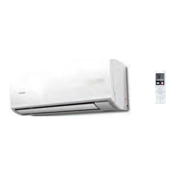
System Configration Parts and Functions Remote controller Indoor Unit Additional functions display Supplemented electrical Operation mode QUITE SLEEP HEALTH POWER heating Remote controller 9. QUIET button 10. HEAT button 11. COOL button 12. AUTO button 13. FAN button fan speed) 14. -
Page 43: Emergency Operation
System Configration Operation Base Operation Emergency operation and test operation Emergency Operation: Use this operation only when the remote controller is defective or lost, and with function of emergency running, air conditoner Remote controller can run automatically for a while. When the emergency operation switch is pressed, the "... -
Page 44: Sleep Operation
System Configration Operation Sleep Operation 4. In FAN mode It has no SLEEP function. Press button to enter additional options, when 5.Set the wind speed change when sleeping cycle display to will flash. And then press If the wind speed is high or middle before setting for the enter to sleep function. - Page 45 System Configration EUROPEAN REGULATIONS Operation CONFORMITY FOR THE MODELS Timer On/Off On-Off Operation All the products are in conformity with the following European provision: 1.After unit starts, select your desired operation mode. - Low Voltage Directive 73/23/EEC 2.Press TIMER button to change TIMER mode. Every - Low Voltage Directive 2006/95/EC time the button is pressed, display changes as follows: -Electomagnetic CompatibilitY 89/336/EEC...
-
Page 46: Replacement Of Air Purifying Filter
System Configration Maintenance For Smart Use of The Air Conditioner Remote Controller Indoor Body Setting of proper room Do not block the air inlet temperature or outlet Proper wipe the air conditioner by using a temperature soft and dry cloth.For serious stains, use a neutral detergent diluted with Do not usewater,wipe the controller water.Wring the water out of the... - Page 47 System Configration Cautions WARNING Please call Sales/Service Shop for the Installation. Do not attempt to install the air conditioner by yourself because improper works may cause electric shock, fire, water leakage. WARNING Check proper When abnormality such as burnt-small found, Use an exclusive immediately stop the operation button and power source...
-
Page 48: Instruction
System Configration Trouble shooting Cautions Before asking for service, check the following Do not obstruct or cover the ventilation grille of the air first. conditoner.Do not put fingers or any other things into the inlet/outlet and swing louver. Phenomenon Cause or check points Do not allow children to play with the air conditioner .In no When unit is stopped, it won't restart... -
Page 49: Installations
Service Diagnosis 7.Service Diagnosis 7.1 Caution for Diagnosis The operation lamp flashes when any of the following errors is detected. 1.When a protection device of the indoor or outdoor unit is activated or when the thermistor malfunctions, disabling equipment operation. 2.When a signal transmission error occurs between the indoor and outdoor units.In either case, conduct the diagnostic procedure described in the following pages. -
Page 50: Error Codes And Description Indoor Display
Service Diagnosis 7.3 Error Codes and Description indoor display Code indication Reference Outdoor Description Page Indoor (LED1 flash times) Communication fault between indoor and Page .58 Indoor Outdoor outdoor units Room temperature sensor failure Page .50 Heat-exchange sensor failure Page .50 Indoor Malfunction Indoor EEPROM error Page .57... -
Page 51: Thermistor Or Related Abnormality
Service Diagnosis 7.3.1 Thermistor or Related Abnormality Indoor Display E1: Room temperature sensor failure E2: Heat-exchange sensor failure Outdoor display LED1 flash 10 times Defrost temperature sensor failure LED1 flash 11 times Suction temperature sensor failure LED1 flash 12 times Ambient temperature sensor failure LED1 flash 13 times Discharge temperature sensor failure Method of The temperatures detected by the thermistors are used to determine thermistors errors. - Page 52 Service Diagnosis 7.3.2 Indoor fan motor malfunction Indoor Display Method of The rotation speed detected by the Hall IC during fan motor operation is used to determine Malfunction abnormal fan motor operation Detection Malfunction when the detected rotation feedback signal don’t received in 2 minutes Decision Conditions Supposed Causes...
- Page 53 Service Diagnosis Turn off power supply and rotate fan by hand Does fan rotate Replace fan motor smoothly? Turn power ON and operate fan Turn off power supply and disconnect fan Does it rotate? motor connector, then turn power ON Check output of fan motor connector Is motor power voltage DC310V...
-
Page 54: Outdoor Dc Fan Motor Fault
Service Diagnosis 7.3.3 Outdoor DC fan motor fault Check whether Terminal on the outdoor mainboard is well inserted. Is it normal? Reinsert the terminals Electrify the machine again and turn it on in the Cool state with the remote controller. check whether motor... -
Page 55: Ipm Protection
Service Diagnosis 7.3.4 IPM protection Outdoor display LED1 flash 2 times. Indoor Display F1 Method of IPM protection is detected by checking the compressor running condition and so on. Malfunction Detection Malfunction The system leads to IPM protection due to over current. Decision The compressor faulty leads to IPM protection. -
Page 56: The Communication Fault Between Ipm And Outdoor Pcb
Service Diagnosis 7.3.5 The communication fault between IPM and outdoor PCB Outdoor display LED1 flash 4 times Indoor Display Method of Communication is detected by checking the IPM module and the outdoor PCB. Malfunction Detection Malfunction The outdoor PCB broken leads to communication fault Decision The IPM module broken leads to communication fault Conditions... -
Page 57: Overheat Protection For Discharge Temperature
Service Diagnosis 7.3.6 Overheat Protection For Discharge Temperature Indoor display Outdoor display LED1 flash 8 times Method of The exhaust temperature control is checked with the temperature being detected Malfunction by the exhaust pipe thermistor. Detection Malfunction When the compressor discharge temperature is above 117 Decision Conditions Supposed... -
Page 58: Eeprom Abnormal
Service Diagnosis 7.3.7 EEPROM abnormal Indoor Display Indoor EEPROM error F12 Outdoor EEPROM error LED1 flash 1 times Method of The Data detected by the EEPROM are used to determine MCU. Malfunction Detection Malfunction When the Data of EEPROM is error or the EEPROM is damaged. Decision Conditions Supposed... -
Page 59: Communication Error Between The Indoor And Outdoor Units
Service Diagnosis 7.3.8 Communication error between the indoor and outdoor units Indoor display Outdoor display LED1 flash 15 times. Method of The date received from the another unit in indoor unit-outdoor unit signal transmission is Malfunction checked whether is normal Detection Malfunction When the date sent from the another unit cannot be received normally,or when the content... -
Page 60: Service Diagnosis
Service Diagnosis Check the indoor mainboard. Measure the voltage between Jumpers 3 and 4 of IC1 on the indoor mainboard with a multimeter. Test the outdoor power supply (230VAC and +310VDC) with a multimeter. If the voltage is of a constant value of 0V DCto5V DC If 230VAC is available but 310DC not, the power module is damaged, replace it... -
Page 61: Power Supply Over Or Under Voltage Fault
Service Diagnosis 7.3.9 Power Supply over or under voltage fault Indoor display Outdoor display: LED1 flash 6 times Method of An abnormal voltage rise or fall is detected by checking the specified voltage detection circuit. Malfunction Detection Malfunction An voltage signal is fed from the voltage detection circuit to the microcomputer Decision Conditions Supposed... -
Page 62: Loop Of The Station Detect Error
Service Diagnosis 7.3.10 Loop of the station detect error Outdoor Display LED1 flash 18 times Indoor Display F11 LED1 flash 19 times Indoor Display F28 Method of The position of the compressor rotor can not detected normally Malfunction Detection Malfunction When the wiring of compressor is wrong or the connection is poor;... - Page 63 Service Diagnosis 7.3.11 Over-current of the compressor Outdoor Display LED1 flash 3 Indoor Display F22 LED1 flash 24 Indoor Display F2 LED1 flash 25 Indoor Display F23 Method of The current of the compressor is too high Malfunction Detection Malfunction When the IPM Module is damaged Decision Or the compressor is damaged...
-
Page 64: Installation Manual Of Room Air Conditioner
Installtion Installation Manual of Room Air Conditioner Preparation Necessary Tools for Installation Selection of Installation Place Indoor Unit - Select a location that is Torque wrench Hammer (17mm,22mm,26mm) Nipper Robust not causing vibration, where the unit can be supported s ufficiently. Pipe cutter Hacksaw Not affected by heat or steam generated in the vicinity, and where the inlet and outlet of... - Page 65 Installtion Accessory parts Making a Hole on the Wall and Fitting the Piping Hole Cover Drain hose (1) Remote controller (1) Make a hole of B mm / inches in diameter, slightly descending to outside the wall. Install piping hole cover and seal it off with putty after installation Cushion (4) AAA dry battery (2) Pitch downward for drainage...
- Page 66 Installtion Outdoor unit Connecting the indoor/outdoor Electric Cable Installation of Outdoor Unit Removing the wiring cover Install according to the instructions on the 1st page of this manual Remove terminal cover at right bottom corner of indoor unit, then take off wiring cover by removing its screws.
- Page 67 Installtion Power Source Installation Connection Loosen the screws on terminal block and insert the wires fully into terminal The power source must be exclusively used for air conditioner. block, then tighten the screws. In the case of installing an air conditioner in a moist place, please install an ea- If wiring is not correct, the unit will not operate properly and it could cause a rth leakage breaker.(GFCI) For installation in other places, use an HVACR circuit breaker of time delay fuse.
-
Page 68: Removal Procedure
Removal Procedure... - Page 69 Removal Procedure...
- Page 70 Removal Procedure...
- Page 71 Removal Procedure Release...
- Page 72 Removal Procedure...
- Page 73 Removal Procedure...
- Page 74 Removal Procedure...
- Page 75 Removal Procedure...
- Page 76 Removal Procedure...
- Page 77 Removal Procedure...
- Page 78 Removal Procedure...
-
Page 79: The Removal Procedure Of Outdoor
Removal Procedure 9.2 The removal procedure of outdoor 9.2.1 Removal of Outdoor panel Step Procedure Points 1. Features Loosen the service Be careful not to cover screw and remove the service cover. Domestic air conditioner... - Page 80 Removal Procedure 2. Remove the panels. Loosen the 4 screws and lift the top panel Loosen the screws of the panel. Pull and remove the front panel. Domestic air conditioner...
- Page 81 Removal Procedure 9.2.2 Romoval of Electrcal Box screws, then lift the electrical box Domestic air conditioner...
- Page 82 Removal Procedure 9.2.3 Romoval of the Side panel screws and remove the side panel. Domestic air conditioner...
- Page 83 Removal Procedure Remove the screws and remove the side panel. Domestic air conditioner...
-
Page 84: Removal Of Fan And Fan Motor
Removal Procedure 9.2.4 Removal of fan and fan motor Put the lead wire Loosen the of motor when remove the fan the propeller fan) Domestic air conditioner... - Page 85 Removal Procedure Step Procedure Points screws and lift the fan motor. Domestic air conditioner...
- Page 86 Removal Procedure Step Procedure Points screws, then lift the Domestic air conditioner...
- Page 87 Removal Procedure Step Procedure Points screws, then lift the proof plate. Domestic air conditioner...
- Page 88 Removal Procedure Step Procedure Points Cut down the and pull out the compressor and remove the Domestic air conditioner...
- Page 89 Removal Procedure Step Procedure Points Domestic air conditioner...
- Page 90 Removal Procedure Step Procedure Points Domestic air conditioner...
- Page 91 Removal Procedure Step Procedure Points Remove the Domestic air conditioner...
-
Page 92: Wiring Diagrams
WiringDiagrams 10.Wiring Diagrams 10.1. INDOOR UNIT up and down CN52 Domestic Air Conditioner... - Page 93 WiringDiagrams 10.2.Outdoor unit Domestic Air Conditioner...
- Page 94 Circuit Diagrams 11.Circuit Diagrams 11.1.INDOORUNIT check/S-T 1-50-ROOM ROOM 1-51-PIPE 1-35-S_T/SW 0011800184 PIPE TJC8-02 SRCK 4.7uF-50V 10nF 10nF 4.7uF-50V COM 2 COM 3 EEPROM TJC8-02 100nF TJC8-02 100uF-16V C3 1 10 0nF ee program 1-36-IR R109 CN48 1-48-RCK 100Ω TEST 1-47-SER 1-5-SCL 1-46-SCK SRCK...
-
Page 95: Outdoorunit
Circuit Diagrams 11.2.OUTDOORUNIT 11.2.1 control board Circuit Diagrams CN10 AC-L OUT AC-N OUT AC-N OUT AC-L OUT CN14 CN13 FUSE1 PTC1 2U/450V T25A 250VAC 400N/PSB400 AC-L S14K350 225/275V 225/275V 225/275V 100/1W 8MH/20A 8MH/20A 103/275V +12V CN16 AC-N 472/250V/275V AC-L AC-L +12V S14K350 S14K350... -
Page 96: Circuit Diagrams
Circuit Diagrams 11.2.2 module board Circuit Diagram C N8 PS 219 97-4A C N3 C N4 D207 C N5 FF AF 30U60 DN C N1 C N6 C 404 C 406 C 405 SGH40N60 UF D 47 4/630 V 47 4/630 V 47 4/275 V (40A@25 AC-L... -
Page 97: Description Of Coding Rules Of Unit Model
Nominal cooling capacity (24000 BTU/h) M-Multi match:one outdoor unit can match different indoor unit The structure code of indoor unit: S(wall-mounted) H-Abbreviation of Haier Examples: HSU-07RD03/R1,It represents wall-mounted split type heat pump air conditioner .The cooling capacity is 7000BTU/h,and the power supply is 220-230V/50Hz,”D” means the developing sequence,and"R1"... - Page 98 The end Sincere Forever Haier Group Chen Huimin Yu Huali Wang Fei 86 532 88936935 Wu Hongjin HSU-24HEG03/R2(DB)-SM...
Need help?
Do you have a question about the HSU24VHG(DB)-G&W and is the answer not in the manual?
Questions and answers