Table of Contents
Advertisement
Advertisement
Table of Contents

Related Manuals for Packard Bell ixtreme M5850


Summary of Contents for Packard Bell ixtreme M5850
- Page 1 M5850 Service Guide PRINTED IN TAIWAN...
-
Page 2: Revision History
Revision History Please refer to the table below for the updates made on ixtreme M5850 series guide. Date Chapter Updated... - Page 3 Copyright Copyright © 2010 by Acer Incorporated. All rights reserved. No part of this publication may be reproduced, transmitted, transcribed, stored in a retrieval system, or translated into any language or computer language, in any form or by any means, electronic, mechanical, magnetic, optical, chemical, manual or otherwise, without the prior written permission of Acer Incorporated.
- Page 4 Conventions The following conventions are used in this manual: SCREEN Denotes actual messages that appear MESSAGES on screen. NOTE Gives bits and pieces of additional information related to the current topic. WARNING Alerts your to any damage that might result from doing or not doing specific actions.
- Page 5 Preface Before using this information and the product it supports, please read the following general information. This Service Guide provides you with all technical information relating to the BASIC CONFIGURATION decided for Acer's "global" product offering. To better fit local market requirements and enhance product competitiveness, your regional office MAY have decided to extend the functionality of a machine (e.g.
-
Page 6: Table Of Contents
Introducing the Motherboard ..........錯誤! 尚未定義書籤。 Features....................2 Mainboard Components ................ 4 Block Diagram............錯誤! 尚未定義書籤。 ixtreme M5850 ..................5 I/O Port Introduction ................9 Hardware Specifications and Configurations..錯誤! 尚未定義書籤。 Using BIOS....................... 16 Setup Utility Menus ..........錯誤! 尚未定義書籤。 Product Information ..........錯誤! 尚未定義書籤。... -
Page 7: Introducing The Motherboard
Chapter1 Introducing the Motherboard Introduction Thank you for choosing the H67 motherboard. This motherboard is a high performance, enhanced function motherboard designed to support the LGA1155 socket for 2nd Generation IntelR CoreTM Family/PentiumR/CeleronR processors for high-end business or personal desktop markets. This motherboard is based on IntelR H67 Chipset for best desktop platform solution. -
Page 8: Features
Features Operating system Windows®7 Home Premium x86/x64, Windows® 7 Home Basic x86, Windows®7 Starter x86 Processor The motherboard uses an LGA1155 type of socket that carries the following Features: Accommodates 2nd Generation IntelR CoreTM Family / PentiumR / CeleronR processors Supports “Hyper-Threading”... - Page 9 Integrated I/O The motherboard comes with the following expansion options: Two PS/2 ports for mouse and keyboard One VGA port One HDMI port Six USB ports One LAN port Audio jacks for microphone, line-in and line-out BIOS Firmware The motherboard uses AMI BIOS that enables users to configure many system features including the following: Power management Wake-up alarms...
-
Page 10: Mainboard Components
Mainboard Components Label Component CPU Socket AMD socket ATX_12V Auxiliary 4-pin power connector SYS_FAN System cooling fan connector CPU_FAN CPU cooling fan connector DIMM1~4 240-pin DDR3 SDRAM slots ATX1 Standard 24-pin ATX power connector CLR_CMOS Clear CMOS jumper ME_DISABLE ME disable header LEDH1 Front panel switch/LED header SATA1~6... -
Page 11: Block Diagram
Block Diagram... -
Page 12: Ixtreme M5850
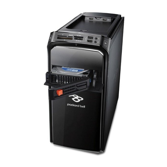
M5850 The computer’s front panel consists of the following: Front view Icon Component Description Connects to USB 2.0 devices USB ports. (e.g.,USB mouse, USB camera). Compact flash. MS: Memory Stick MS/MS Pro MS Pro: Memory Stick PRO Micro SD Micro Secure Digital. -
Page 13: Rear View
Rear view Icon Component Description PS/2 keyboard connector High Definition Multimedia Interface HDMI HDMI Port Connects to USB 2.0 devices USB 2.0 ports (e.g., USB mouse, USB camera). Accepts input from external Microphone jack microphones. PS/2 mouse connector Lights to indicate the status of wireless Network port LAN communications. - Page 14 Audio Jack Function Table Color/Use Headphone 5.1CH Blue Line-in Line-in Rear Speaker Rear Speaker Green Headphone Front speaker Front speaker Front speaker Pink Mic-in Mic-in Mic-in Center & bass...
-
Page 15: I/O Port Introduction
I/O Port Introduction The backplane of the motherboard has the following I/O ports: Component Description Use the upper PS/2 port to connect a PS/2 pointing PS2 Mouse device. USB Ports Use the USB ports to connect USB devices. Connect an RJ-45 jack to the LAN port to connect your LAN Port computer to the Network. -
Page 16: System Peripherals
System Peripherals IXTREME M5850 series computer consist of the system itself, and system peripherals, like a mouse, keyboard, card reader and a set of speakers (optional). This section provides a brief description of the basic system peripherals. Mouse (PS/2 or USB, manufacturing option) The included mouse is a standard two-button wheel mouse. - Page 17 Card Reader (Option) Memory cards are used in a wide selection of digital cameras, PDAs, MP3 players and mobile phones. Selected computers include an “all-in-one”memory card reader that allows you read and write the most common types, such as SD (Secure Digital)™/ MMC (Multi Media Card™), CF (Compact Flash®), xD (XD-PICTURE CARD), Micro SD and MS/MS Pro (Memory Stick®).
-
Page 18: Hardware Specifications And Configurations
Hardware Specifications and Configurations Processor Item Specification LGA1155 socket for 2nd Generation IntelR CoreTM Type Family/ PentiumR/CeleronR processors Socket socket LGA1155 Speed Depends on CPU which is configured Depends on CPU which is configured BIOS Item Specification BIOS code programmer Afudos BIOS version P01-A0 (or newer version) -
Page 19: Audio Interface
System Memory Item Specification slots Memory slot number Support memory size per socket 1GB to 4GB Support maximum memory size 16 GB Support memory type DDR3 DRAM Support memory interface DDR3 1066/1333 Support memory module package 240-pin DIMM Support parity check feature ECC checking with double-bit detect and single-bit Support to Error Correction Code (ECC) feature correct... - Page 20 IDE Interface Item Specification IDE controller Intel H67 Number of SATA connector Support bootable CD-ROM USB Port Item Specification Universal HCI USB 2.0/3.0 USB Class Support legacy keyboard for legacy mode USB Number support up to 12 ports Power Management (Suspend to (Suspend to Devices...
- Page 21 Power Management Function (ACPI support function) Device Standby Mode Independent power management timer for hard disk drive devices (0-15 minutes, time step=1 minute). Hard disk drive goes into Standby mode (for ATA standard interface). Disable V-sync to control the VESA DPMS monitor. Resume method: device activated (Keyboard for DOS, keyboard &...
-
Page 22: Using Bios
Chapter2 Using BIOS About the Setup Utility The computer uses the latest “American Megatrends Inc.” BIOS will support for Windows Plug and Play. The CMOS chip on the motherboard contains the ROM setup instructions for configuring the motherboard BIOS. The BIOS (Basic Input and Output System) Setup Utility displays the system’s configuration status and provides you with options to set system parameters. - Page 23 BIOS Setup Utility(Main) Pressing the DEL key accesses the BIOS Setup Utility: The default BIOS setting for this motherboard applies for most conditions with optimum performance. It is not suggested to change the default values in the BIOS setup and the manufacture takes no responsibility to any damage caused by changing the BIOS settings.
-
Page 24: Updating The Bios
Updating the BIOS You can download and install updated BIOS for this motherboard from the manufacturer’s Web site. New BIOS provides support for new peripherals, improvements in performance, or fixes for known bugs. Install new BIOS as follows: If your motherboard has a BIOS protection jumper, change the setting to allow BIOS flashing. If your motherboard has an item called Firmware Write Protect in Advanced BIOS features, disable it. - Page 25 BIOS Setup Utility(Advanced) This option displays basic information about your system. Miscellaneous Scroll to this item and press <Enter> to view the following screen: AHCI PORT1~4 This motherboard supports four SATA channels and each channel allows one SATA device to be installed. Use these items to configure each device on the IDE channel.
- Page 26 Spread Spectrum (Enabled) If you enable spread spertrum, it can significantly reduce the EMI (Electro-Magnetic interface) generated by the system and voltage according to its temperature. Bootup Num-lock (On) This item determines if the Num Lock key is active or inactive at system start-up time. USB Beep Message (Disabled) This item disables/enables the beep during USB device enumeration.
-
Page 27: Integrated Peripherals
DVMT Mode(DVMT) DVMT is Dynamic Video Memory Technology. This item helps you select video mode. DVMT/Fixed Memory Size(256MB) When set to Fixed Mode, the graphics driver will reserve a fixed portion of the system memory as graphics memory. When set to DVMT Mode, the graphics chip will dynamically allocate system memory as graphics memory, according to system anf graphics requirements. -
Page 28: Pc Health Status
Onboard Graphics Controller (Enabled) This item allows you to enable or disable the onboard controller. Onboard Audio Controller (Enabled) This item enables or disables the onboard audio controller. Onboard LAN Controller (Enabled) This option allows you to control the onboard LAN device. Onboard LAN Option ROM (Disabled) This item enables or disables the onboard LAN option ROM function Press <Esc>... - Page 29 System Component Characteristics These items display the monitoring of the overall inboard hardware health events, such as System & CPU temperature, CPU voltage, CPU & system fan speed,...etc. • CPU Fan Speed • System Fan Speed • CPU Core • + 1.05V •...
- Page 30 BIOS Setup Utility(Power) This page sets up some parameters for system power management operation. APCI Suspend Mode(S3(STR)) Use this item to define how your system suspends. In the default, S3(STR), the suspend mode is suspend to RAM, i.e., the system shuts down with the exception of a refresh current to the system memory. Deep Power off Mode (Enabled) This item allows users to enable or disable the Deep Power off Mode.
- Page 31 BIOS Setup Utility(Security) This page enables you to set setup administrator and password. Supervisor Password (Not Installed) This item indicates whether a supervisor password has been set. If the password has been installed, Installed displays. If not, Not Installed displays. User Password This item allows you to change user password.
- Page 32 BIOS Setup Utility(Boot options) This page enables you to set the keyboard NumLock state. Set Priority Order This item enables you to set boot priority order. 1st Boot Device/2nd Boot Device/3rd Boot Device Use these items to determine the device order the computer uses to look for an operating system to load at start-up time.
- Page 33 Hard Disk Drive Priority (Press Enter) Scroll to this item and press <Enter> to view the following screen: Press <Esc> to return to the Boot Options menu page. Optical Disk Drive Priority (Press Enter) Scroll to this item and press <Enter> to view the following screen: Press <Esc>...
- Page 34 Removable Device Priority (Press Enter) Scroll to this item and press <Enter> to view the following screen: Press <Esc> to return to the Boot Options menu page. Network Device Priority (Press Enter) Scroll to this item and press <Enter> to view the following screen: Press <Esc>...
-
Page 35: Load Default Settings
BIOS Setup Utility(Exit) This page enables you to exit system setup after saving or without saving the changes. Save & Exit Setup Use this item enables you to save the changes that you have made and exit. Discard Changes and Exit Use this item enables you to discard any changes that you have made and exit. -
Page 36: Machine Disassembly And Replacement
Chapter3 Machine Disassembly and Replacement To disassemble the computer, you need the following tools: Wrist grounding strap and conductive mat for preventing electrostatic discharge. Wire cutter. Phillips screwdriver (may require different size). NOTE: The screws for the different components vary in size. During the disassembly process, group the screws with the corresponding components to avoid mismatches when putting back the components. -
Page 37: General Information
General Information Before You Begin Before proceeding with the disassembly procedure, make sure that you do the following: Turn off the power to the system and all peripherals. Unplug the AC adapter and all power and signal cables from the system. -
Page 38: Standard Assembly Process
Standard Assembly Process 1. Opening the chassis Remove the two screws Remove side cover 2. Removing front bezel and HDD Cage Pushing three hooks... - Page 39 Disconnect the cable housing then you can remove front bezel. Remove the screw Pulling out the HDD cage...
- Page 40 3. Install the PSU Pushing PSU into chassis Fix four screws Connect U’s light power cable...
- Page 41 4. Setting the Motherboard Motherboard view Open the CPU cover and remove the plastic cover Put the CPU in the seat and close the cove...
- Page 42 Tie CPU fan cable Pulling in CPU fan power cable to MB Fix four screws of CPU Cooler connect to MB.
- Page 43 Open the Memory latch Press down the memory Memory install rule DIMM4 DIMM2 DIMM3 DIMM1 1x1G 2x1G 3x1G 4x1G 1x2G 2x2G 1x1G +1x2G...
- Page 44 5. Assembly motherboard Pushing rear I/O Shield in chassis Insert the motherboard and fix eight screws ATV 12V power cable insert...
- Page 45 ATX power cable insert and the cable need to rotate 3 times. Pulling in Audio/FRONT USB/TOP USB/ CARD READER /FRONT cable to MB and put in cable clip 6. Insert the ODD/HDD Remove the ODD EMI bracket when SKU need...
- Page 46 Insert the ODD devices HDD Carrier SKU with HDD Carrier SKU without HDD Carrier Fix two screws for each ODD and pulling in ODD SATA cable on Motherboard ODD Installed on SATA4 when SKU have HDD Carrier Master ODD Installed on SATA2/ Slave ODD Installed on SATA4 when SKU have no HDD Carrier SKU with HDD Carrier SKU without HDD Carrier...
- Page 47 Remove the HDD Carrier Install the HDD devices...
- Page 48 Insert the HDD Carrier to Chassis Pulling in HDD Carrier SATA cable on Motherboard HDD Carrier Installed on SATA3 Fix the four screws for each HDD of HDD cage...
- Page 49 Put five hooks to Chassis and push HDD Cage down 6.10 Fix the screw of HDD cage and Pulling in HDD SATA cable on Motherboard Master HDD Installed on SATA0 Slave HDD Installed on SATA1 when SKU have HDD Carrier Slave HDD Installed on SATA2 when SKU have no HDD Carrier 6.11 HDD/ODD install rule...
- Page 50 7. Close the Front Bezel Connect light cable and Insert the cable in chassis Insert three hooks to chassis in right side and Clasp three hooks in left side 8. Insert Add-on card Remove the bracket...
- Page 51 Rotate the bracket Install VGA card on motherboard Connect 6 PIN power cable...
- Page 52 Install TV / Modem card on motherboard Install USB 3.0 card on motherboard (option) Combination the 15 PIN POWER cable with SATA Connect...
- Page 53 Connect PATA power cable Fix the screw 8.10 Close the bracket...
- Page 54 9. Install system fan Twist the fan cable Insert cable housing to 3 pin in MB and Tie the fan cable with 12V cable Fix the four screws...
- Page 55 10. Overview...
-
Page 56: Standard Disassembly Process
Standard Disassembly Process 1. Opening the computer Disconnect the three screws fixed in the side-panel. Remove the side panel 2. Removing the Front Bezel Remove the three hooks... - Page 57 Disconnect the cable housing then you can remove front bezel. 3. Removing the Add-on Card Rotate the PCI lock. Disconnect the screw fixed in the bracket...
- Page 58 Disconnect 6 PIN power cable in VGA Card Press the PCI ear lever (highlighted in red) and pull the leaver outwards a little to release the PCI latch then remove it. Disconnect 6 PIN power cable in USB 3.0 Card(option)
- Page 59 Pull the leaver outwards a little to release the PCI latch then remove the card. Pull the leaver outwards a little to release the PCI latch then remove other add-on card. 4. Removing the HDD Disconnect the screw fixed in the HDD cage.
- Page 60 Disconnect the SATA HDD cable and HDD power-cable from the rear of HDD and MB Remove the HDD cage Disconnect the eight screws fixed in HDD cage side.
- Page 61 5. Removing the ODD Disconnect the screw fixed in ODD cage Disconnect the SATA ODD cable and ODD power-cable from the rear of ODD and MB Remove the ODD...
- Page 62 6. Removing the System Fan Disconnect cable housing and loosen the cable Disconnect the four screws fastening fan to the case 7. Removing the Main Board 24pin power connector and 4 pin power connector Disconnect the...
- Page 63 Disconnect the Audio/FRONT USB/TOP USB/ CARD READER /FRONT cable from the main board Disconnect the eight screws fastening the main board to the case and Remove the Main Board NOTE: Circuit boards >10 cm² has been highlighted with the yellow rectangle as above image shows. Please detach the Circuit boards and follow local regulations for disposal.
- Page 64 Remove the RTC battery NOTE: RTC battery has been highlighted with the yellow circle as above image shows. Please detach the RTC battery and follow local regulations for disposal. Release the four latch show bellow then remove the Memory Disconnect the CPU cooler power-cable from the main board...
- Page 65 Release the CPU Cooler screw x4 then remove it Remove the CPU 8. Removing the power-supply Disconnect the three screws fixed in the rear chassis...
- Page 66 9. Removing the HDD in HDD Carrier Push HDD carrier button and cover down slowly Press orange latch towards the right, open the handle and pull out HDD Carrier Rotate rubber pin in Carrier and removing HDD...
- Page 67 Insert HDD Carrier to case and close the cover 10. Removing FRONT IO/POWER SWTICH PCB/TOP USB/CARD READER 10.1 Cut cable tie...
- Page 68 10.2 Press ten hooks on TOP Bezel , disconnect cable and remove it...
- Page 69 10.3 Disconnect the two screws fastening top USB bracket to the case and the two screws fastening PCB to bracket...
- Page 70 10.4 Press the bottom hook on PCB holder, remove PCB assembly; Press two side hooks on PCB holder, remove POWER SWTICH PCB...
- Page 71 10.5 Disconnect the screw fastening FRONT IO bracket to the case, disconnect the button cable and the screw , then rotate bracket finger outward, and pull out the FRONT IO 10.6 Disconnect the two screws fastening Card Reader bracket to the case, disconnect the button cable and the screw...
-
Page 72: Troubleshooting
Chapter4 Troubleshooting This chapter provides troubleshooting information for the ixtreme M5850 Service Guide Power-On Self-Test (POST) POST Error Messages List Error Symptoms List Undetermined Problems... -
Page 73: Power-On Self-Test (Post)
Power-On Self-Test (POST) Each time you turn on the system, the Power-on Self Test (POST) is initiated. Several items are tested during POST, but is for the most part transparent to the user. The Power-On Self Test (POST) is a BIOS procedure that boots the system, initializes and diagnoses the system components, and controls the operation of the power-on password option. - Page 74 Checkpoint Description Initializes the CPU. The BAT test is being done on KBC.Program the keyboard controller command byte is being done after Auto detection of KB/MS using AMI KB-5. Early CPU Init Start -- Disable Cache – Init Local APIC Set up boot strap processor Information Set up boot strap processor for POST Enumerate and set up application processors...
- Page 75 Checkpoint Description Initializes DMAC-1 & DMAC-2. Initialize RTC date/time. Test for total memory installed in the system. Also, Check for DEL or ESC keys to limit memory test. Display total memory in the system. Mid POST initialization of chipset registers. Detect different devices (Parallel ports, serial ports, and coprocessor in CPU, …...
- Page 76 Checkpoint Description Takes care of runtime image preparation for different BIOS modules. Fill the free area in F000h segment with 0FFh. Initializes the Microsoft IRQ Routing Table. Prepares the runtime language module. Disables the system configuration display if needed. Initialize runtime language module. Display boot option popup menu. Displays the system configuration screen if enabled.
-
Page 77: Post Error Messages List
POST Error Messages List If you cannot run the diagnostics program tests but did receive a POST error message, use “POST Error Messages List” to diagnose system problems. If you did not receive any error message, look for a description of your error symptoms in “Error Symptoms List” on page 66. NOTE: When you have deemed it necessary to replace an FRU, and have done so, you must run a total system check to ensure that no other activity has been affected by the change. - Page 78 BIOS Messages Action/FRU Keyboard Error Or Cannot initialize the keyboard. Make sure the keyboard is attached correctly and no No Keyboard keys are pressed during POST. To purposely configure the system without a Present keyboard, set the error halt condition in Setup to HALT ON ALL, BUT KEYBOARD. The BIOS then ignores the missing keyboard during POST.
-
Page 79: Error Symptoms List
Error Symptoms List NOTE: To diagnose a problem, first find the error symptom in the left column. If directed to a check procedure, replace the FRU indicated in the check procedure. If no check procedure is indicated, the first Action/ FRU listed in right column is the most likely cause. - Page 80 Error Symptom Action/FRU CD/DVD-ROM Drive NOTE: Ensure CD/DVD-ROM drive is configured correctly in BIOS Setup, cable/jumper are set correctly and its laser beam is clean before diagnosing any CD/DVD-ROM drive problems. CD/DVD-ROM drive LED doesn't come 1. CD/DVD-ROM drive on but works normally. CD/DVD-ROM drive LED flashes for 1.
- Page 81 Error Symptom Action/FRU Video and Monitor Video memory test failed. 1. Remove all non-factory-installed cards. Video adapter failed. 2. Load default settings (if screen is readable). 3. Main board Display problem: 1. Monitor signal connection/cable. 2. Monitor - Incorrect colors 3.
- Page 82 Error Symptom Action/FRU Executing software shutdown from 1. Load default settings. Windows98 Start menu does not turn off 2. Reload software from Recovery CD. the system. (Only pressing power switch can turn off the system). No system power, or power supply fan is 1.
-
Page 83: Undetermined Problems
Undetermined Problems If an error message is present, go to “POST Error Messages List” on page 64. If you did not receive any messages, if the symptom is listed in “or “Error Symptoms List” on page 66. If you still cannot solve the problem, continue with this check: Check the power supply voltages. -
Page 84: Jumper And Connector Information
Chapter5 Jumper and Connector Information Safety Precautions Follow these safety precautions when installing the motherboard Wear a grounding strap attached to a grounded device to avoid damage from static electricity Discharge static electricity by touching the metal case of a safely grounded object before working on the motherboard Leave components in the static-proof bags they came in Hold all circuit boards by the edges. -
Page 85: Checking Jumper Settings
Checking Jumper Settings This section explains how to set jumpers for correct configuration of the motherboard. Do not over-tighten the screws as this can stress the motherboard. Setting Jumpers Use the motherboard jumpers to set system configuration options. Jumpers with more than one pin are numbered. - Page 86 Checking Jumper Settings The following illustration shows the location of the motherboard jumpers. Pin 1 is labeled. Jumper Settings Jumper Type Description Setting (Default) IIIustration 1-2: NORMAL. 2-3: CLEAR CLR_CMOS 3-pin CLEAR CMOS Before clearing the CMOS, make sure CLR_COMS to turn the system off 1-2: NORMAL.
-
Page 87: Connecting Case Components
Connecting Case Components After you have installed the motherboard into a case, you can begin connecting the motherboard components. Refer to the following: 1 Connect the CPU cooling fan cable to CPU_FAN. 2 Connect the standard power supply connector to ATX1 3 Connect the auxiliary case power supply connector to ATX_12V. - Page 88 CPU_FAN: Cooling Fan Power Connectors Signal Name Function System Ground +12V Power +12V Sense Sensor CPU FAN control SYS_FAN: Cooling Fan Power Connector Signal Name Function System Ground +12V Power +12V Sense Sensor CPU FAN control ATX1:ATX 24-pin Power Connector Signal Name Signal Name +3.3V...
-
Page 89: Front Panel Header
Front Panel Header The front panel header (PANEL1) provides a standard set of switch and LED headers commonly found on ATX or Micro ATX cases. Refer to the table below for information: Signal Name Function Signal Name Function HD_LED_P Hard disk LED(+) FP PWR/SLP *MSG LED(+) HD_LED_N... -
Page 90: Installing Hardware
Installing Hardware Installing the Processor Caution: When installing a CPU heatsink and cooling fan make sure that you DO NOT scratch the motherboard or any of the surface-mount resistors with the clip of the cooling fan.If the clip of the cooling fan scrapes across the motherboard, you may cause serious damage to the motherboard or its components. - Page 91 CPU Installation Procedure The following illustration shows CPU installation components. Opening of the Load Plate Put your thumb on the tail of the load plate and press the tail down Rotate the load plate to fully open position. Disengaging of the Load Lever· Hold the hook of lever and pull it to the left side to clear retention tab.
- Page 92 Installing Memory Modules This motherboard accommodates two memory modules. It can support four 240-pin DR3 1066/1333. The total memory capacity is 16 GB. DDR3 SDRAM memory module table Memory Memory Bus DDR3 1066 533 MHz DDR3 1333 667 MHz Do not remove any memory module from its antistatic packaging until you are ready to install it on the motherboard.
- Page 93 Installing Serial ATA Hard Drives To install the Serial ATA (SATA) hard drives, use the SATA cable that supports the Serial ATA protocol. This SATA cable comes with an SATA power cable. You can connect either end of the SATA cable to the SATA hard drive or the connector on the motherboard.
- Page 94 Installing Add-on Cards The slots on this motherboard are designed to hold expansion cards and connect them to the system bus. Expansion slots are a means of adding or enhancing the motherboard’s features and capabilities. With these efficient facilities, you can increase the motherboard’s capabilities by adding hardware that performs tasks that are not part of the basic system.
- Page 95 Follow these instructions to install an add-on card: Remove a blanking plate from the system case corresponding to the slot you are going to use. Install the edge connector of the add-on card into the expansion slot. Ensure that the edge connector is correctly seated in the slot.
- Page 96 Connecting Optional Devices Refer to the following for information on connecting the motherboard’s optional devices: F_AUDIO1: Front Panel Audio header This header allows the user to install auxiliary front-oriented microphone and line-out ports for easier access. Signal Name Signal Name PORT 1L AUD_GND PORT 1R...
- Page 97 SATA 1~6: Serial ATA connectors These connectors are used to support the new Serial ATA devices for the highest date transfer rates (3 Gb/s ), simpler disk drive cabling and easier PC assembly. It eliminates limitations of the current Parallel ATA interface.
-
Page 98: Fru (Field Replaceable Unit) List
Chapter6 FRU (Field Replaceable Unit) List Exploded Diagram Chassis_PB 30L w/ HDD carrier ME BOM Description Item Description Item P5_30L_LFFT_SIDE_COVER P5_30L_MB_STUD_6_32_H6_6 P5_30L_PCI_LOCK SCREW_M632-6 PCI_SHIELDING RIVET_32_UMBRELLA_HEAD P5_30l_MAIN_CHASSIS RIVET_32_FLAT_HEAD P5_30L_CHASSIS_SUPPORT FRONT-COVER-PB P5_30L_MB_SUPPORT HDD-CARRIER-GEAR PB_RIGHT_SIDE_COVER ODD_DOOR_TOP TOP_USB_ASM CD-AXES TOP_USB_PCB PACKARD_BELL_LOGO POWER_PCB_HOLDER ODD_BUTTON_TOP_LOCK POWER_PCB BEZEL-FRONT FRONT_SWITCH_HOLDER CD-DOOR-SPRING... - Page 99 Description Item Description Item RAY_LED_5_1 HDD-CARRIER- SPRING-PIN LIGHT_BASE hdd-carrier-handle ODD_BUTTON_TOP HDD-CARRIER-LATCH ODD_BUTTON_BOTTOM SWITCH SPRING-03 FRONT-LENS HDD_LENS BEZEL-FRONT-PANEL CILUN-02 PG-07M YAXIANG-COVER REVOLVE-GAN SPRING-03 P5_30L_HDD_CHRRINR_BKT_B P5_30L_HDD_CHRRINR_BKT_A P5_30L_HDD_CHRRINR_BKT_EMI TATA SCREW_M3 Hdd-carrier-latch HDD-CARRIER-MAIN HDD_CARRIER_EMI_BKT HDD-CARRIER-AXIS-SPRING...
- Page 101 Chassis_PB 30L w/o HDD carrier ME BOM Description Item Description Item P5_30L_LFFT_SIDE_COVER SCREW_M632-6 P5_30L_PCI_LOCK RIVET_32_UMBRELLA_HEAD PCI_SHIELDING RIVET_32_FLAT_HEAD P5_30l_MAIN_CHASSIS FRONT-COVER-PB P5_30L_CHASSIS_SUPPORT ODD_DOOR_BOTTOM P5_30L_MB_SUPPORT ODD_DOOR_TOP PB_RIGHT_SIDE_COVER CD-AXES TOP_USB_ASM PACKARD_BELL_LOGO TOP_USB_PCB ODD_BUTTON_TOP_LOCK POWER_PCB_HOLDER BEZEL-FRONT POWER_PCB CD-DOOR-SPRING FRONT_SWITCH_HOLDER LED_D5 FIO_M150_-02-001 TOP-BEZEL-BASE P5_30L_USB_BRACKET TOP-LENS PB-NS_P5_MCR TOP-BEZEL-BASE_PANEL LED-HOUSING_CLED_1J TOP-BEZEL-COVER...
- Page 102 Description Item Description Item ODD_BUTTON_TOP ODD_BUTTON_BOTTOM SPRING-03 FRONT-LENS HDD_LENS BEZEL-FRONT-PANEL SWITCH...
-
Page 104: Fru List
FRU List The FRU list will be updated later.
Need help?
Do you have a question about the ixtreme M5850 and is the answer not in the manual?
Questions and answers