Table of Contents
Advertisement
Quick Links
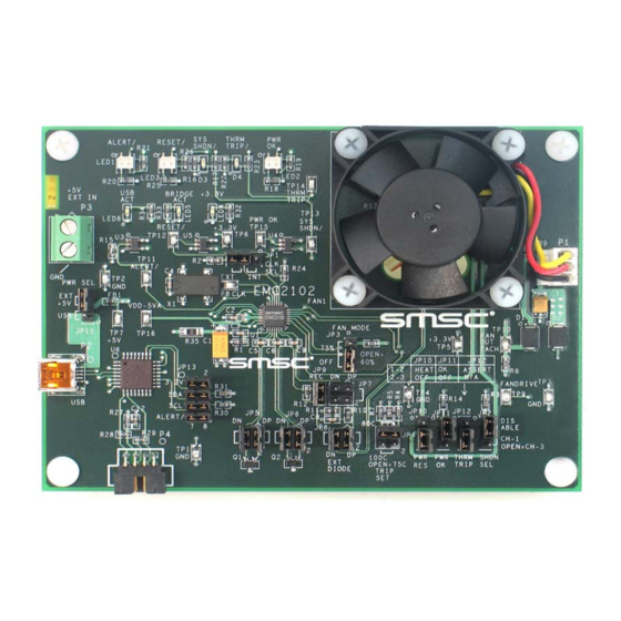
Fan Speed Control with the EMC2102 Device
Insert EVB graphic/photo here
(this text can be removed on master page view)
Copyright © 2007 SMSC or its subsidiaries. All rights reserved.
Circuit diagrams and other information relating to SMSC products are included as a means of illustrating typical applications. Consequently, complete information
sufficient for construction purposes is not necessarily given. Although the information has been checked and is believed to be accurate, no responsibility is assumed
for inaccuracies. SMSC reserves the right to make changes to specifications and product descriptions at any time without notice. Contact your local SMSC sales office
to obtain the latest specifications before placing your product order. The provision of this information does not convey to the purchaser of the described semiconductor
devices any licenses under any patent rights or other intellectual property rights of SMSC or others. All sales are expressly conditional on your agreement to the terms
and conditions of the most recently dated version of SMSC's standard Terms of Sale Agreement dated before the date of your order (the "Terms of Sale Agreement").
The product may contain design defects or errors known as anomalies which may cause the product's functions to deviate from published specifications. Anomaly
sheets are available upon request. SMSC products are not designed, intended, authorized or warranted for use in any life support or other application where product
failure could cause or contribute to personal injury or severe property damage. Any and all such uses without prior written approval of an Officer of SMSC and further
testing and/or modification will be fully at the risk of the customer. Copies of this document or other SMSC literature, as well as the Terms of Sale Agreement, may be
obtained by visiting SMSC's website at http://www.smsc.com. SMSC is a registered trademark of Standard Microsystems Corporation ("SMSC"). Product names and
company names are the trademarks of their respective holders.
SMSC DISCLAIMS AND EXCLUDES ANY AND ALL WARRANTIES, INCLUDING WITHOUT LIMITATION ANY AND ALL IMPLIED WARRANTIES OF
MERCHANTABILITY, FITNESS FOR A PARTICULAR PURPOSE, TITLE, AND AGAINST INFRINGEMENT AND THE LIKE, AND ANY AND ALL WARRANTIES
ARISING FROM ANY COURSE OF DEALING OR USAGE OF TRADE. IN NO EVENT SHALL SMSC BE LIABLE FOR ANY DIRECT, INCIDENTAL, INDIRECT,
SPECIAL, PUNITIVE, OR CONSEQUENTIAL DAMAGES; OR FOR LOST DATA, PROFITS, SAVINGS OR REVENUES OF ANY KIND; REGARDLESS OF THE
FORM OF ACTION, WHETHER BASED ON CONTRACT; TORT; NEGLIGENCE OF SMSC OR OTHERS; STRICT LIABILITY; BREACH OF WARRANTY; OR
OTHERWISE; WHETHER OR NOT ANY REMEDY OF BUYER IS HELD TO HAVE FAILED OF ITS ESSENTIAL PURPOSE, AND WHETHER OR NOT SMSC HAS
BEEN ADVISED OF THE POSSIBILITY OF SUCH DAMAGES.
USER MANUAL
SMSC EMC2102
Revision 0.2 (09-17-07)
Advertisement
Table of Contents

Related Manuals for SMSC EMC2102


Summary of Contents for SMSC EMC2102
- Page 1 Any and all such uses without prior written approval of an Officer of SMSC and further testing and/or modification will be fully at the risk of the customer. Copies of this document or other SMSC literature, as well as the Terms of Sale Agreement, may be obtained by visiting SMSC’s website at http://www.smsc.com.
-
Page 2: Table Of Contents
DC Fan Basics - Poles, Tach Meter Pulses and Edges ....... . . 35 Characterizing a DC Fan with EVB-EMC2102 and ChipMan ......36 6.2.1... - Page 3 Fan Speed Control with the EMC2102 Device 6.2.8 Using the Tested Parameters ..........38...
- Page 4 Figure 4.1 EMC2102 Fan Control Evaluation System........
- Page 5 Fan Speed Control with the EMC2102 Device List of Tables Table 5.1 Register Change Summary for Experiment 2 ........15 Table 5.2 Register Change Summary for Experiment 3 .
-
Page 6: Overview
2 Audience This user manual assumes that the reader is familiar with the functionality of the EMC2102 device and its evaluation board. The goal of the user manual is to help users to evaluate the new EMC device using Chip Manager (ChipMan) software provided by SMSC. This user manual also can be used as a reference material for other EMC devices which have fan control features. -
Page 7: Figure 4.1 Emc2102 Fan Control Evaluation System
Fan Speed Control with the EMC2102 Device U SB C able P C w / C hipM an S oftw are E V B -E M C 2102 Figure 4.1 EMC2102 Fan Control Evaluation System Figure 4.2 EVB-EMC2102 Board USER MANUAL SMSC EMC2102 Revision 0.2 (09-17-07) -
Page 8: Basic Operation Experiments
This experiment is designed to gain familiarity with both the EMC2102 device, and the application software, ChipMan. The ChipMan application can be used to configure the EMC2102 device and to monitor the status of the device. It includes tools to capture and plot data at rates up to 10Hz. Additionally, ChipMan can be used to review previously saved data. -
Page 9: Figure 5.2 Chipman Device Selection Window
Window". Click on the HWM icon to show the different windows available. The EMC2102 WatchDog will have timed out at this point, and the on-board DC fan will be running at 100%. Note: Starting the ChipMan application without the USB cable/EVB connected to the PC, an error message "Supported company ID on device not found"... -
Page 10: Figure 5.3 Selecting The Device And Master Controller Type
Fan Speed Control with the EMC2102 Device Figure 5.3 Selecting the Device and Master Controller Type Figure 5.4 ChipMan Operation Window USER MANUAL Revision 0.2 (09-17-07) SMSC EMC2102... -
Page 11: Figure 5.5 Changing Fan Speed
The next step will be to load the CMF file. Simply select File at the top of the window, and "Import" from the pull-down menu. A pop-up window will let the user to locate the right CMF. Select the appropriate file and click "open". The CMF file will then load up the values into the EMC2102 device. -
Page 12: Plotting From Chipman
Fan Speed Control with the EMC2102 Device Figure 5.5 Changing Fan Speed 5.1.3 Plotting From ChipMan The ChipMan software has the ability to plot register values in real-time, up to 10Hz continuous rate. To select a register to plot, highlight its name or value, and right-click. A menu with a single entry "Add register to Plot"... -
Page 13: Experiment 2 - Rpm Based Closed-Loop Fan Control
Experiment 2 - RPM Based Closed-Loop Fan Control The experiment 2 is designed to gain familiarity with the closed-loop RPM controller implemented in the EMC2102. This experiment will discuss the effects of gain, spin-up, and minimum settings on the closed-loop performance. -
Page 14: Basic Rpm Based Fan Control
5.2.3 Effects of Loading The EMC2102 has the ability to overcome changes in fan current requirements for a given RPM setting due to aging, a blocked vent, dust, etc. This is because the controller does not rely on absolute drive settings, but rather on driving the PID loop error to "0"... -
Page 15: Register Change Summary
Fan Speed Control with the EMC2102 Device Fan was covered The cover was removed Figure 5.10 Effects of Loading 5.2.4 Register Change Summary Table 5.1, "Register Change Summary for Experiment 2" lists all register value changes from the default cmf load to accomplish the tests. -
Page 16: Experiment 3 - Spin-Up Configuration Options
Fan Control Parameters The spin-up routine is a special algorithm that the EMC2102 uses to boot up the fan. In manual control (open loop) mode, it is only invoked when starting from a ‘0’ value in the FAN Drive Setting register 51h. -
Page 17: Getting Started
5.3.3 Forced Kick Function The EMC2102 has a forced 100% kick at turn-on. This feature drives the fan at maximum voltage for ¼ of the time set by the SPINUP_TIME[1:0] bits in register 53h. The plots in Figure 5.12, "Forced Kick Function"... -
Page 18: Spin-Up Time
Invalid TACH Count Figure 5.13 60% Spin Level Setting Note: When a fan starts, the first TACH count captured by the EMC2102 may not reflect the fan’s speed correctly, since the counting clock (32.768 kHz) could only partially fill the counting window, which will cause a higher speed reading. -
Page 19: Register Change Summary
Fan Speed Control with the EMC2102 Device 5.3.6 Register Change Summary Table 5.2, "Register Change Summary for Experiment 3" lists all register value changes from the default cmf load to accomplish the tests. Table 5.2 Register Change Summary for Experiment 3... -
Page 20: Experiment 4 - Rpm Drive Mode Rate Controls
Controlling the ramp rate can improve the performance of the fan control loop by limiting the slew rate of the fan drive. The EMC2102 uses the UPDATE bits in the FAN Configuration register (52h, bits [2:0]) to determine the time interval between two updates of the controller output, and uses the FAN Step register (54h) to determine the maximum allowed hexadecimal count (STEP) of the output (Refer to Figure 5.11 "Fan Control Parameters"... -
Page 21: Figure 5.16 Default Step Size With Different Update Settings
Fan Speed Control with the EMC2102 Device UPDATE = 100 ms UPDATE = 400 ms Figure 5.16 Default Step Size with Different UPDATE Settings In the next experiment (Figure 5.17, "Default UPDATE with Different Step Size Settings"), two different maximum step sizes, 16 and 63, were used. with the 63 STEP SIZE setting, the output takes less steps (updates) from 4000 rpm to 7500 rpm because it gives the fan more power to follow the desired rpm settings. -
Page 22: Register Change Summary
Fan Speed Control with the EMC2102 Device Figure 5.18 Exceptionally Slow Rate 5.4.3 Register Change Summary Table 5.3, "Register Change Summary for Experiment 4" lists all register value changes from the default cmf load to accomplish the tests. Table 5.3 Register Change Summary for Experiment 4... -
Page 23: Experiment 5 - Optimizing Rpm Control Response
This experiment is designed to gain familiarity with the parameters that affect the closed-loop controller implemented in the EMC2102. All these registers are located on the Fan Setting page in ChipMan. This experiment will go through each register, examining the effects of parametric changes on the closed-loop controller in RPM mode. -
Page 24: Fan Minimum Drive Register (55H) And Valid Tach Count (56H)
Fan Speed Control with the EMC2102 Device 5.5.3 FAN Minimum Drive Register (55h) and Valid TACH Count (56h) These two registers assist the user in defining the operational environment for a given fan. The Minimum Drive register is an absolute minimum value the RPM controller may drive to in an attempt to achieve low RPM settings. -
Page 25: Register Change Summary
Fan Speed Control with the EMC2102 Device 5.5.4 Register Change Summary Table 5.4, "Register Change Summary for Experiment 7" lists all register value changes from the default cmf load to accomplish the tests. Table 5.4 Register Change Summary for Experiment 7... -
Page 26: Experiment 6 - Limits And Alerts
Fan Speed Control with the EMC2102 Device Experiment 6 - Limits and Alerts This experiment is designed to gain familiarity with the control registers for generating fan related alarms and alerts associated with the EMC2102. The CMF file for this experiment is EMC2102_default.cmf. -
Page 27: Register Change Summary
Fan Speed Control with the EMC2102 Device TACH Target (57h) Fan Drive Setting (51h) TACH Reading (58h) Stall Interrupt Status 2 (23h) Figure 5.22 Fan Spin and Stall 5.6.3 Register Change Summary All register values are default for the tests in this section. -
Page 28: Experiment 7 - Troubleshooting
Since the fan speed at the end of spin-up routine is always below the minimum valid speed (a function of 56h), the EMC2102 will think the fan is not running, and will try to restart the fan with spin-up routine over and over. -
Page 29: Figure 5.24 Theoretical Plot Of Case 1
Fan Speed Control with the EMC2102 Device Fan Speed RPM for (RPM) 100% Drive Target Speed Valid Speed rpm60 or rpm75 Fan Speed ¼ of Spin Up Time Spin Up Time Check TACH Figure 5.24 Theoretical Plot of Case 1... -
Page 30: Figure 5.26 Spin-Up Case 1 Fix 2
EMC2102 will go to the normal operation after the spin-up routine. Using the EVB-EMC2102 to test this situation with rpm75 (~5650 rpm), simply set the Valid TACH register (56h) with 4500 rpm and start the fan with TACH Target (57h) = 5500 rpm (Figure 5.28, "Spin-... -
Page 31: Figure 5.28 Spin-Up Case 2
Since the fan speed at the end of spin-up routine is higher than the minimum valid speed, the EMC2102 should go to the normal operation after the spin-up routine. However, because the large speed difference between the spin-up level speed (rpm60 or rpm75) and the target speed, the closed- loop controller will try to make a big adjustment of its output to reach the target speed. -
Page 32: Figure 5.30 Spin-Up Case 3
Fan Speed Control with the EMC2102 Device Using the EVB-EMC2102 to test this situation with rpm75 (~5650 rpm), simply set the Valid TACH register (56h) with 4500 rpm, set the UPDATE (52h[2:0]) = 100ms and start the fan with 4700 rpm, the spin-up routine starts over ‘and over... -
Page 33: Figure 5.32 Theoretical Plot Of Case 4
At the end of spin-up routine, the closed-loop control will drive the fan up to reach the target, therefore the fan speed will never be lower than the valid speed. The EMC2102 will go to the normal operation after the spin-up routine. -
Page 34: Figure 5.34 Spin-Up Case 5
In this case, the spin-up routine is too short to make the fan reach a speed higher than the valid speed. Since the EMC2102 cannot detect a valid TACH at the end of spin-up routine, it will try to restart the fan. -
Page 35: Appendix
Figure 6.2 Output Signal of a 2-pole Fan EMC2102 uses a clock (32.768KHz for example) to fill in a window between a programmable number of Tachometer edges. A counter starts on a specific rising edge and keeps counting until it sees the ‘set’... -
Page 36: Characterizing A Dc Fan With Evb-Emc2102 And Chipman
5.1, "Experiment 1 - Manual Fan Control". Unplug the on-board DC fan from connector P1 Connect the DC fan to be tested to P1 (refer to EVB-EMC2102 User Manual for the DC fan connector pinouts) USER MANUAL Revision 0.2 (09-17-07) -
Page 37: Set The Correct Limit2K Value
Start the fan with 100% output drive (register 51h = 255h) EMC2102 assumes that it is driving a 2-pole fan by default. If the fan speed in register 58h does not match the fan’s maximum speed specified in its datasheet, then it is not a 2-pole fan. The... -
Page 38: Determine The Spin-Up Levels (Rpm60 And Rpm75)
Valid TACH Count Speed (Function of Register 56h) The EMC2102 will not respond to any TACH Target (57h) value that has a corresponding speed slower than Minimum Valid TACH Speed + Margin, unless the value is FFh which will stop the fan. This ensures that the RPM control algorithm will not drive too low.
Need help?
Do you have a question about the EMC2102 and is the answer not in the manual?
Questions and answers