
Related Manuals for Vaillant VRC 430f


Summary of Contents for Vaillant VRC 430f
- Page 1 For the operator / for the heating engineer Operating and Installation Manual VRC 430f Weather compensator controller with radio transmission VRC 430f...
-
Page 3: Table Of Contents
For the operator Operating instructions VRC 430f Weather compensator controller with radio transmission VRC 430f Contents Equipment properties ..........4 Operating concept ..........8 Application ................4 4.3.1 Show various screens ..........9 Product specifications ............4 4.3.2 Changing parameters..........9 4.3.3 Operation in the simplified basic display ..11 Notes on the documentation ...... -
Page 4: Equipment Properties
The outside temperature is measured by a separate sensor, mounted outdoors, and the signal is The VRC 430f can be part of a new heating and water transmitted to the VRC 430f. heating installation or can be retrofitted in an existing The room temperature depends only on your preset installation. -
Page 5: Notes On The Documentation 1
CE label These operating instructions are included with the vari- The CE label indicates compliance of the VRC 430f con- ous system components and the additional components. troller with the fundamental requirements of the rele- –... -
Page 6: Notes On Operation
– the VRC 430f must not be covered by furniture, cur- waste. Ensure that the batteries are disposed of proper- tains or other objects – the radiator valves in the room where the VRC 430f is fitted must be fully opened "Thermostat" means that the VRC 430f records the current room temperature and uses this for control purposes. -
Page 7: Operation 4
15 minutes for the radio receiv- er to call up and display the latest data (e.g. outside temperature, time with integrated CDCF 77 radio signal receiver). If dashes (--) are displayed continuously, con- sult your heating engineer. Operating instructions VRC 430f 0020042470_01... -
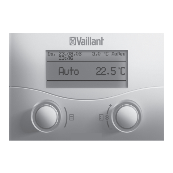
Page 8: Overview Of The Display (Field)
Operating concept The parameters and settings (operating values) of The operator input in the default display is described in the VRC 430f are shown on different screens. Section 4.3.3. The screens are sub-divided into: The operating concept described below applies to the –... -
Page 9: Show Various Screens
Auto HC 1 Time programme > Change target hot water 06 : 00 - 10 : 40 21.5 °C Fig. 4.5 Jump to various modifiable parameters > Select day/block Fig. 4.4 Examples of various screens Operating instructions VRC 430f 0020042470_01... - Page 10 > Change room target temperature Fig. 4.7 Changing a parameter value Click the right-hand dial. The value displayed is confirmed and adopted for con- trol purposes. The value is saved and is no longer high- lighted. Operating instructions VRC 430f 0020042470_01...
-
Page 11: Operation In The Simplified Basic Display
Turn the right-hand dial. The value for the room temperature changes by 0.5 °C for each turn (click) of the dial. Click the right-hand dial once the required value for the room target temperature has been reached. Operating instructions VRC 430f 0020042470_01... -
Page 12: Period Of Validity Of Changed Control System Target Values
Fig. 4.11. tained at this level. The prerequisite for this is that the selected heating curve corresponds to the conditions and the thermo- stat function is activated. Operating instructions VRC 430f 0020042470_01... -
Page 13: Operating Level For Operator, Operating Level For Expert Technician
Operation 4 Operating level for operator, operating level for expert technician 25 ° The VRC 430f controller has two operating levels. Each level contains several screens in which the various pa- rameters can be displayed, adjusted or changed. 20 °... - Page 14 This relationship is rep- resented by heating curves. A range of heat- ing curves are available (see Section 4.7.3). Table 4.4 Screens in the Operator level Operating instructions VRC 430f 0020042470_01...
-
Page 15: Edit Screens (Examples)
Set the start time by turning the right-hand dial. Fig. 4.13 Screen 2 (example) Each step of the dial changes the time by 10 minutes. Once the desired starting time is displayed, confirm by clicking the right-hand dial. Operating instructions VRC 430f 0020042470_01... -
Page 16: Programming Holiday Periods
The field is highlighted. Turn the right-hand dial to set the room tempera- ture (values from 5 °C to 30 °C in half degree steps and frost protection function are possible). Click the right-hand dial. Operating instructions VRC 430f 0020042470_01... -
Page 17: Entering Parameters For The Heating Circuit
The field is highlighted. Turn the right-hand dial until the desired value is displayed (values from 0.2 to 4.0 are possible, see Fig. 4.15). Click the right-hand dial. Operating instructions VRC 430f 0020042470_01... -
Page 18: Entering Parameters For Hot Water Generation
14 (example) On the right-hand side of the colon you can enter a new name (numbers 0-9, spaces, capital/small letters). Pro- ceed as follows : Turn the left-hand dial until you reach screen "Change names". Operating instructions VRC 430f 0020042470_01... -
Page 19: Status And Error Messages 5
The connection between the radio receiver unit and ap- pliance is faulty. Contact your heating engineer. Fig. 5.1 Removing the VRC 430f controller No radio communication Radio communication between the VRC 430f and radio Controller VRC 430f receiver unit is faulty. 2 Wall plinth Contact your heating engineer. - Page 20 The display and lighting are activated as soon as you turn or click one of the dials. If the ap- pliance is not used for more than one minute the basic display returns and switches off after approx. 10 minutes. Operating instructions VRC 430f 0020042470_01...
-
Page 21: Installation Instructions
Maintenance ............14 Safety instructions and regulations ....4 Safety instructions ..........4 Factory customer service, Regulations ...............4 manufacturer's guarantee ......15 Vaillant Service ............15 Assembly ............5 Vaillant warranty........... 15 Scope of delivery ............5 Accessories ...............5 Recycling and disposal ........15 Installating the unit ..........5 Installing the wireles transmitter Technical data ..........16... -
Page 22: Notes On The Documentation
Symbols used Power is supplied via 4 batteries (alkaline AA/LR6 1.5V) Please observe the safety instructions in this manual for with the VRC 430f and via a solar cell with the wireless the installation of the appliance. outdoor sensor VR 20/21. -
Page 23: Identification Plate
Even so, inappropriate or non-intended use may ad- versely affect the appliance and other material assets. The controller VRC 430f is designed as a weather com- pensator and timer-controlled heating unit with or without hot water generation/circulation pump in con- junction with a Vaillant heating unit with eBUS interface. -
Page 24: Safety Instructions And Regulations
3 Safety instructions and regulations Safety instructions and regulations The VRC 430f must be installed by a suitably qualified heating engineer, who is responsible for adhering to the existing standards and regulations. We accept no liabili- ty for any damage caused by failure to observe these in- structions. -
Page 25: Assembly 4
Assembly 4 Assembly Solar module VR 68 The VR 68 solar module can be used by the VRC 430f The VRC 430f must be installed on a wall in the living to control a solar installation. area. The VRC 430f is supplied with the following... -
Page 26: Wall Mounting The Wireless Receiver
Press the radio receiver unit carefully onto the wall socket until it snaps into place. The plug connector on the rear of the wireless receiver unit must fit in the plug connector provided on the wall socket. Installation instructions VRC 430f 0020042470_01... -
Page 27: Wall-Mounting The Controller
Note! The radio outdoor sensor must always be oper- ated in conjunction with the heating unit, oth- Fig. 4.6 Installing of the VRC 430f erwise no information (e.g. outside tempera- ture) will be transmitted to the radio receiver. Controller VRC 430f... -
Page 28: Installation
Depending on use, the batteries last between approx. 1 and 1.5 years. Carefully press the controller onto the wall plinth until it snaps into place. Check the quality of the radio signal path as de- scribed in Section 6.1. Installation instructions VRC 430f 0020042470_01... -
Page 29: Initial Commissioning 6
The button on the radio receiver unit is only re- quired for "teaching" components on the radio network following the replacement of parts. The VRC 430f operator control concept is explained in Section 4.3 of the operating instructions. 4.3 Explana- tion. -
Page 30: Expert Technician Level
The expert technician level includes screens C1 to C26 wireless network. and screens A1 to A6 as previously described. The screens C1 to C26 appear in the VRC 430f in the Turn the left-hand dial clockwise by one indexing same sequence, as shown in Table 6.1 below. -
Page 31: Restoring The Parameters To The Default Settings
After entering the correct code you automatically reach screen C1. Restoring the parameters to the default settings The default settings for the VRC 430f can be restored as follows: Press both dials simultaneously for 10 seconds. This takes you to the default settings screen. - Page 32 OFF, MO, TU, eters The cylinder is heated WE, TH, FR, up to 70 °C for an hour SA, SU, MO- Start time of Le- 0:00 24:00 0:10 4:00 gionella protection Table 6.2 Screen, Expert technician level Installation instructions VRC 430f 0020042470_01...
- Page 33 Outside tempera- Adjustment of outdoor ture adjustment sensor Room temperature Adjustment of room correction temperature sensor Display contrast Software versions Software version Display of version per module (A) number Table 6.2 Screens, Expert technician level (continued) Installation instructions VRC 430f 0020042470_01...
-
Page 34: Function Floor Drying
Handing over the appliance to the owner The floor-drying function is used to "heat dry” a freshly- The operator of the VRC 430f must receive instructions laid heating layer according to building regulations. on how to handle and operate of the controller. -
Page 35: Factory Customer Service, Manufacturer's Guarantee 7
To ensure regular servicing, it is strongly recommended Appliance that arrangements are made for a Maintenance Agree- Neither the VRC 430f nor any of its accessories may be ment. Please contact Vaillant Service Solutions disposed of in the household waste. Make sure the old (0870 6060 777) for further details. -
Page 36: Technical Data
Permissible operating temperature -35 … + 60 °C Width mm Transmission frequency 868 MHZ Depth mm Transmitting power < 10 mW Table 9.1 Technical specifications VRC 430f Range: in free field > 100m Parameter Radio receiver unit in building approx. 25 m Operating voltage Umax max. -
Page 37: Glossary
The operating modes "Auto" (automatic), "Manual" and "OFF" exist. You can use the operating modes to specify how you wish your room heating or water heating to be controlled (see operating instructions, Section 4.3.2, Table 4.2). Installation instructions VRC 430f 0020042470_01... - Page 38 Switch-on room temp. (operating level for expert technicians) You can specify whether or not the temperature sensor fitted in the VRC 430f should be used in screen C8 "HC1 Parameter" under the "Switch-on room temp." menu item. Outside temperature in ºC...
- Page 39 The factory setting (as-supplied condition) is for auto- matic changeover not to take place (Selection: Off). If the VRC 430f is equipped with the wireless outdoor sensor VR 21 that receives the radio time signal DCF77, the summer/winter changeover takes place automatical- ly;...
Need help?
Do you have a question about the VRC 430f and is the answer not in the manual?
Questions and answers