
Related Manuals for UNI-T UT205A


Summary of Contents for UNI-T UT205A
-
Page 1: Table Of Contents
Model UT205A/206A: OPERATING MANUAL Table of Contents Title Page Overview Unpacking Inspection Safety Information Rules For Safe Operation International Electrical Symbols The Meter Structure Functional Buttons Display Symbols Measurement Operation A. AC Current Measurement B. DC Voltage Measurement C. AC Voltage Measurement D. - Page 2 General Specifications Accuracy Specifications A. AC Current B. DC Voltage C. AC Voltage D. Resistance E. Diode and Continuity Test F. Frequency G. Duty Cycle (Model UT205A only) H. Temperature (Model UT206A only) Maintenance A. General Service B. Replacing the Battery...
-
Page 3: Overview
To avoid electric shock or personal injury, read the “Safety Information” and “Rules for Safety Operation” carefully before using the Meter. The Model UT205A and UT206A (hereafter referred to as “the Meter”) are a low consumption AC clamp meter with stabilize functions, safety operations, and reliable performance. -
Page 4: Unpacking Inspection
Model UT205A/206A: OPERATING MANUAL Unpacking Inspection Open the package case and take out the Meter. Check the following items carefully to see any missing or damaged part: Item Description Operating Manual 1 piece Test Lead 1 pair Model UT206A: Point Contact Temperature Probe... -
Page 5: Safety Information
Model UT205A/206A: OPERATING MANUAL Safety Information This Meter complies with the standards IEC61010: in pollution degree 2, overvoltage category (CAT. II 600V / CAT III 300V) and double insulation. CAT II: Local level, appliance, PORTABLE EQUIPMENT etc., with smaller transient voltage overvoltages than CAT. -
Page 6: Rules For Safe Operation
Model UT205A/206A: OPERATING MANUAL Rules For Safe Operation Warning To avoid possible electric shock or personal injury, and to avoid possible damage to the Meter or to the equipment under test, adhere to the following rules: Check for the lever is in good condition when measuring AC current. - Page 7 Model UT205A/206A: OPERATING MANUAL Use the proper terminals, function, and range for your measurements. When using the test leads, keep your fingers behind the finger guards. Disconnect circuit power and discharge all high-voltage capacitors before testing To avoid harms to you or damages to the Meter from electric shock, please do not attempt to apply higher than 600V between the terminals and grounding.
- Page 8 Model UT205A/206A: OPERATING MANUAL Do not use or store the Meter in an environment of high temperature, humidity, explosive, inflammable and strong magnetic field. The performance of the Meter may deteriorate after dampened...
-
Page 9: International Electrical Symbols
Model UT205A/206A: OPERATING MANUAL International Electrical Symbols AC (Alternating Current) DC (Direct Current) AC or DC Grounding Double Insulated Fuse Deficiency of Built-In Battery Continuity Test Diode Conforms to Standards of European Union Warning. Refer to the Operating Manual High Voltage Terminal... -
Page 10: The Meter Structure
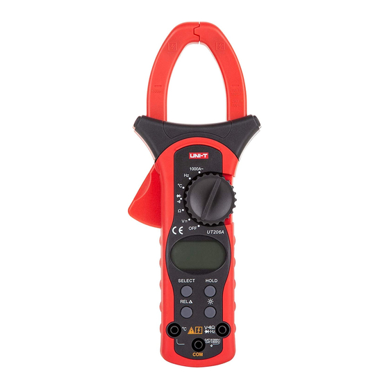
Model UT205A/206A: OPERATING MANUAL The Meter Structure (see figure 1) Transformer Jaws designed to pick up the AC current flowing through the conductor. Rotary Switch. LCD Display. Function Buttons Input Terminals Trigger. Press the lever to open the transformer jaws. When the pressure on the lever is released, the jaws will close. -
Page 11: Functional Buttons
Model UT205A/206A: OPERATING MANUAL Functional Buttons Below table indicated for information about the functional button operations. Button Operation Performed Turn the display backlight on and off. In order to avoid the hazard arising from mistaken readings in insufficient light or poor vision, please use Display Backlight function. - Page 12 (UT206A only) measuring mode except in frequency and duty cycle, the Meter beeps. UT206A: Switches between AC voltage and DC SELECT Voltage measurement, and continuity and diode measurement; the Meter beeps. UT205A: Switches between continuity and diode measurement; the Meter beeps.
- Page 13 Model UT205A/206A: OPERATING MANUAL Button Operation Performed When it is under sleep mode, press to activate SELECT the Meter at the effective measurement range, e.g. continuity buzzer. Auto power off feature will be disabled until switch off and turn on the Meter again.
-
Page 14: Display Symbols
Model UT205A/206A: OPERATING MANUAL Display Symbols (see figure 2) (figure 2) - Page 15 Model UT205A/206A: OPERATING MANUAL Number Symbol Meaning Data hold is active. Indicator for AC Voltage. The battery is low. Warning: To avoid false readings, which could lead to possible electric shock or personal injury, replace the battery as soon as the battery indicator appears.
- Page 16 Model UT205A/206A: OPERATING MANUAL Number Symbol Meaning The continuity buzzer is on. Test of diode Centigrade. The unit of temperature. The relative value mode is on to display the stored value minus the present Volts. The unit of voltage. V, mV Millivolt.
-
Page 17: Measurement Operation
Model UT205A/206A: OPERATING MANUAL Measurement Operation Make sure the Sleep Mode is not on if you found there is no display on the LCD after turning on the Meter. Make sure the Low Battery Display is not on; otherwise false readings may be provided. - Page 18 Model UT205A/206A: OPERATING MANUAL To measure current, do the following: 1. Set the rotary switch to the current measurement mode. 2. Check the lever is in good condition. 3. Press the lever to open the transformer jaws. 4. Center the conductor within the transformer jaw.
-
Page 19: Dc Voltage Measurement
Model UT205A/206A: OPERATING MANUAL DC Voltage Measurement (See figure 4) Warning To avoid harms to you or damages to the Meter from electric shock, please do not attempt to measure voltages higher than 600V although readings may be obtained. To measure DC voltage, connect the Meter as follows: Black 1. -
Page 20: Ac Voltage Measurement
Model UT205A/206A: OPERATING MANUAL Note In each range, the Meter has an input impedance of 10M . This loading effect can cause measurement errors in high impedance circuits. If the circuit impedance is less than or equal to 10k , the error is negligible (0.1% or less). -
Page 21: Measuring Resistance
Model UT205A/206A: OPERATING MANUAL D. Measuring Resistance (see figure 5) Warning To avoid damages to the Meter or to the devices under test, disconnect circuit power and discharge all the high-voltage capacitors before measuring resistance. To measure resistance, connect the Meter as follows: Black 1. - Page 22 Model UT205A/206A: OPERATING MANUAL To obtain precision readings in low-resistance measurement, that is the range of 400.0 , short-circuit the input terminals beforehand, using the relative measurement function button REL to automatically subtract the value measured when the testing leads are short-circuited from the reading.
-
Page 23: Testing For Diodes And Continuity
Model UT205A/206A: OPERATING MANUAL E. Testing for Diodes and Continuity (See figure 6) Warning To avoid damages to the Meter or to the devices under test, disconnect circuit power and discharge all the high-voltage capacitors before testing for continuity. Black... - Page 24 Model UT205A/206A: OPERATING MANUAL 3. For continuity test: a. Press SELECT to switch between Diode and Continuity test. b. Connect the test lead to the two end of the circuit under test. c. The buzzer sounds if the resistance of a circuit under test is less than 100 .
-
Page 25: Frequency And Duty Cycle (%) Measurement
Model UT205A/206A: OPERATING MANUAL F. Frequency and Duty Cycle (%) Measurement (See figure 7) UT205A has both frequency and duty cycle measurement feature UT206A has only frequency measurement feature To measure frequency and duty cycle, connect the Meter as follows: 1. - Page 26 Model UT205A/206A: OPERATING MANUAL d. Connect the test leads across with the object being measured. The measured frequency value or duty cycle value shows on the display. 2. UT206A a. Insert the red test lead into the Hz terminal and the black test lead into the COM terminal.
-
Page 27: Temperature Measurement (Model Ut206A Only)
Model UT205A/206A: OPERATING MANUAL G. Model UT206A: Temperature Measurement (See figure 8) To measure temperature, connect the Meter as follows: C terminal 1. Insert the red temperature probe into the and the black temperature probe into the COM terminal. 2. Set the rotary switch to 3. -
Page 28: Operation Of Hold Mode
Model UT205A/206A: OPERATING MANUAL Operation of Hold Mode Warning To avoid possibility of electric shock, do not use Hold mode to determine if circuits are without power. The Hold mode will not capture unstable or noisy readings. The Hold mode is applicable to all measurement functions. -
Page 29: The Use Of Relative Value Mode(Model Ut206A Only)
Model UT205A/206A: OPERATING MANUAL The Use of Relative Value Mode (UT206A only) The REL mode applies to all measurement functions except frequency and duty cycle. It subtracts a stored value from the present measurement value and displays the result. For instance, if the stored value is 20.0V and the present measurement value is 22.0V, the reading would be 2.0V. -
Page 30: The Select Button
Model UT205A/206A: OPERATING MANUAL The SELECT Button It uses for selecting the required measurement function when there is more than one function at one position of the rotary switch. Turning on the Display Backlight Warning In order to avoid the hazard arising from mistaken readings in insufficient light or poor vision, please use Display Backlight function. -
Page 31: General Specifications
Model UT205A/206A: OPERATING MANUAL General Specifications Maximum Voltage between any Terminals and Grounding: 600V rms or 600V DC. Maximum Current Measurement: 1000A. of Transformer Jaw: Maximum Jaw Size: 40mm. Maximum Display: Digital: 3999, 3 3/4 digits Overload Display: Range: Auto Polarity Display: Negative display: “-“... -
Page 32: Accuracy Specifications
Model UT205A/206A: OPERATING MANUAL Battery Type: One piece of 9V (NEDA1604 or 6F22 or 006P). Battery Deficiency: Display Dimensions (HxWxL): 236mm x 97mm x 40mm Weight: Approximate 350g (battery included). Safety/Compliances: IEC61010 CAT. II 600V / CAT III 300V overvoltage and double insulation standard. -
Page 33: Ac Current
Model UT205A/206A: OPERATING MANUAL A. AC Current Range Resolution Accuracy Remarks 400A 0.1A (1.5%+5) Frequency response 50Hz~60Hz. Display effective value of sine wave 800A (2%+5) (mean value response). 1000A >800A (3%+5) B. DC Voltage Range Resolution Accuracy Overload Protection Remarks (0.8%+3) -
Page 34: Ac Voltage
Model UT205A/206A: OPERATING MANUAL AC Voltage Overload Range Resolution Accuracy Remarks Protection Input impedance around 10M . Displays effective value of sine 10mV (1.2%+5) 600V DC wave (mean value response). 600V AC 100mV 400V Frequency response: 40Hz ~ 400Hz. (1.5%+5) 600V D. -
Page 35: Diode And Continuity Test
Model UT205A/206A: OPERATING MANUAL Range Resolution Accuracy Overload Protection (1%+2) 400k 500V DC or AC (1.2%+2) (1.5%+2) E. Diode and Continuity Test Function Range Resolution Overload Remarks Displays the nearest value Diode of forward voltage drop 500V DC or AC... -
Page 36: Frequency
Input Voltage: 10Hz- (0.1%+3) 500V DC or VAC 1MHz: 300mV rms a 30V rms; 10MHz 0.001Hz 1MHz: 600mV rms a 5V rms G. Duty Cycle (Model UT205A only) Range Resolution Accuracy Overload Protection 0.1%-99.9% 0.1% For reference only 500V DC or AC H. -
Page 37: Maintenance
Model UT205A/206A: OPERATING MANUAL Maintenance This section provides basic maintenance information including battery replacement instruction. Warning Do not attempt to repair or service your Meter unless you are qualified to do so and have the relevant calibration, performance test, and service information. -
Page 38: Replacing The Battery
Model UT205A/206A: OPERATING MANUAL B. Replacing the Battery (See figure 9) Warning To avoid false readings, which could lead to Screw possible electric shock or personal injury, replace the battery as soon as the battery indicator “ ” appears. Make sure the transformer jaw and the test leads... - Page 39 Model UT205A/206A: OPERATING MANUAL To replace the battery: 1. Turn the rotary switch of the Meter to OFF position and remove all the connections from the terminals. 2. Remove the screw from the battery compartment, and separate the battery compartment from the case bottom.
- Page 40 Model UT205A/206A: OPERATING MANUAL Copyright 2006 Uni-Trend Group Limited. All rights reserved. Manufacturer: Uni-Trend Technology (Dongguan) Limited Dong Fang Da Dao Bei Shan Dong Fang Industrial Development District Hu Men Town, Dongguan City Guang Dong Province China Postal Code: 523 925...
Need help?
Do you have a question about the UT205A and is the answer not in the manual?
Questions and answers