
Related Manuals for UNI-T UT20B


Summary of Contents for UNI-T UT20B
-
Page 1: Table Of Contents
Model UT20B: OPERATING MANUAL Table of Contents (1) Title Page Overview Unpacking Inspection Safety Information Rules For Safe Operation International Electrical Symbols Rotary Switch Display Symbols Measurement Operation AC Voltage Measurement DC Current Measurement C. Square Wave Output D. Battery Test Diodes Test Measuring Resistance G. -
Page 2: Title Page
Model UT20B: OPERATING MANUAL Table of Contents (2) Title Page General Specifications Accuracy Specifications AC Voltage DC Current C. Square Wave Output D. Battery Test Diodes Test Resistance Test G. DC Voltage Maintenance General Service Replacing the Battery C. Replacing the Fuses... -
Page 3: Overview
Model UT20B: OPERATING MANUAL Overview This Operation Manual covers information on safety and cautions. Please read the relevant information carefully and observe all the Warnings and Notes strictly. Warning To avoid electric shock or personal injury, read the "Safety Information" and "Rules for Safe Operation"... -
Page 4: Unpacking Inspection
Model UT20B: OPERATING MANUAL Unpacking Inspection Open the packing case and take out the Meter. Check the following items carefully to see any missing or damaged part: Item Description Operating Manual 1 piece Test Lead (affixed onto the Meter) 1 pair 12V Battery (A23) (installed) 1 piece In the event you find any missing or damage, please contact your dealer immediately. -
Page 5: Safety Information
Model UT20B: OPERATING MANUAL Safety Information This Meter complies with the standards IEC61010: in pollution degree 2, overvoltage category (CAT. II 300V) and double insulation. CAT. II: Local level, appliance, PORTABLE EQUIPMENT etc., with smaller transient voltage overvoltages than CAT. III. Use the Meter only as specified in this operating manual, otherwise the protection provided by the Meter may be impaired. -
Page 6: Rules For Safe Operation
Model UT20B: OPERATING MANUAL Rules For Safe Operation (1) Warning To avoid possible electric shock or personal injury, and to avoid possible damage to the Meter or to the equipment under test, adhere to the following rules: Before using the Meter inspect the case. Do not use the Meter if it is damaged or the case (or part of the case) is removed. - Page 7 Model UT20B: OPERATING MANUAL Rules For Safe Operation (2) When the Meter working at an effective voltage over 60V in DC or 30V rms in AC, special care should be taken for there is danger of electric shock. Use the proper function and range for your measurements. Do not use or store the Meter in an environment of high temperature, humidity, explosive, inflammable and strong magnetic field.
- Page 8 Model UT20B: OPERATING MANUAL Rules For Safe Operation (3) electrical specifications replacement parts. The internal circuit of the Meter shall not be altered at will to avoid damage of the Meter and any accident. Soft cloth and mild detergent should be used to clean the surface of the Meter when servicing.
-
Page 9: International Electrical Symbols
Model UT20B: OPERATING MANUAL International Electrical Symbols AC (Alternating Current) DC (Direct Current) Grounding. Double Insulated. Deficiency of Built-In Battery. Diode. Fuse. Warning. Refer to the Operating Manual. Conforms to Standards of European Union. -
Page 10: Rotary Switch
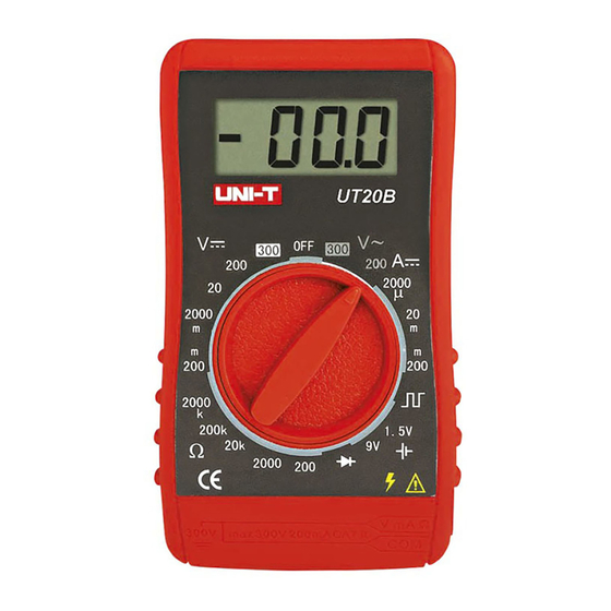
Model UT20B: OPERATING MANUAL Rotary Switch Below table indicated for information about the rotary switch positions. Rotary Switch Position Function Turn on or off the power. AC voltage measurement range from 200V to 300V. DC current measurement range from 2000 A to 200mA. Square wave output. -
Page 11: Measurement Operation
Model UT20B: OPERATING MANUAL Measurement Operation (1) A. AC Voltage Measurement Warning To avoid harms to you or damages to the Meter from electric shock, please do not attempt to measure voltages higher than 300V rms although readings may be obtained. The AC voltage measurement positions are: 200V and 300V. - Page 12 Model UT20B: OPERATING MANUAL Measurement Operation (2) Note If the value of voltage to be measured is unknown, use the maximum measurement position (300V) and reduce the range step by step until a satisfactory reading is obtained. In each range, the Meter has an input impedance of approx. 0.5M . This loading effect can cause measurement errors in high impedance circuits.
-
Page 13: Dc Current Measurement
Model UT20B: OPERATING MANUAL Measurement Operation (3) B. DC Current Measurement Warning Never attempt an in-circuit current measurement where the open-circuit voltage between the circuit and ground is greater than 300V. If the fuse burns out during measurement, the Meter may be damaged or the operator himself may be hurt. - Page 14 Model UT20B: OPERATING MANUAL Measurement Operation (4) Break the current path to be tested. Connect the red test lead to the more positive side of the break and the black test lead to the more negative side of the break. Turn on power to the circuit.
-
Page 15: Square Wave Output
Model UT20B: OPERATING MANUAL Measurement Operation (5) C. Square Wave Output Warning To avoid damages to the Meter, do not allow output terminals to reach higher than 10V. To measure square wave output proceed as follows: Set the rotary switch to Connect the test leads across with the object being measured. -
Page 16: Battery Test
Model UT20B: OPERATING MANUAL Measurement Operation (6) D. Battery Test To test the battery proceed as follows: Set the rotary switch to the 1.5V or 9V measurement position in range. Connect the test leads across with the battery being measured ensuring the polarity is correct. -
Page 17: Diodes Test
Model UT20B: OPERATING MANUAL Measurement Operation (7) E. Diodes Test Warning To avoid damages to the Meter or to the devices under test, disconnect circuit power and discharge all the high-voltage capacitors before testing diodes. Use the diode test to check diodes, transistors, and other semiconductor devices. The diode test sends a current through the semiconductor junction, and then measures the voltage drop across the junction. - Page 18 Model UT20B: OPERATING MANUAL Measurement Operation (8) For forward voltage drop readings on any semiconductor component, place the red test lead on the component’s anode and place the black test lead on the component’s cathode. The measured value shows on the display. Note In a circuit, a good diode should still produce a forward voltage drop reading of 0.5V to 0.8V;...
-
Page 19: Measuring Resistance
Model UT20B: OPERATING MANUAL Measurement Operation (9) F. Measuring Resistance Warning To avoid damages to the Meter or to the devices under test, disconnect circuit power and discharge all the high-voltage capacitors before measuring resistance. The resistance measurement positions are: 200 , 2000 , 20k , 200k and 2000k . To measure resistance, connect the Meter as follows: Set the rotary switch to an appropriate measurement position in range. - Page 20 Model UT20B: OPERATING MANUAL Measurement Operation (10) Note If the value of resistance to be measured is unknown, use the maximum measurement position (2000k ) and reduce the range step by step until a satisfactory reading is obtained. The test leads can add 0.1 to 0.2 of error to resistance measurement.
-
Page 21: Dc Voltage Measurement
Model UT20B: OPERATING MANUAL Measurement Operation (11) The LCD displays " " indicating open-circuit for the tested resistor or the resistor value is higher than the maximum range of the Meter. When resistance measurement has been completed, disconnect the connection between the testing leads and the circuit under test. - Page 22 Model UT20B: OPERATING MANUAL Measurement Operation (12) Connect the test leads across with the object being measured. The measured value shows on the display. Note If the value of voltage to be measured is unknown, use the maximum measurement position (300V) and reduce the range step by step until a satisfactory reading is obtained.
-
Page 23: General Specifications
Model UT20B: OPERATING MANUAL General Specifications Maximum Voltage between any Terminals and Grounding : 300V rms. Fused Protection Input Terminal : 0.2A, 250V fast type, 5x20 mm. : Display: 1999. Maximum Display Measurement Speed : Updates 2.5 times /second. : Operating: 0 C~40 C (32 F~104... -
Page 24: Accuracy Specifications
Model UT20B: OPERATING MANUAL Accuracy Specifications (1) Accuracy: (a% reading + b digits), guarantee for 1 year. Operating temperature: 23 Relative humidity: <75%. Temperature coefficient: 0.1 x (specified accuracy) / 1 A. AC Voltage Range Resolution Accuracy Overload Protection 200V 100 mV (2.5%+15) 300V DC or AC rms... -
Page 25: Dc Current
Model UT20B: OPERATING MANUAL Accuracy Specifications (2) B. DC Current Range Resolution Accuracy Overload Protection 2000 A 20mA 10 A (2.5%+10) 0.2A, 250V fast type fuse, 5x20mm. 200mA 100 A C. Square Wave Output Range Remark Output approx. at 50Hz square wave. As a simple signal source with 47k resistance output. -
Page 26: Battery Test
Model UT20B: OPERATING MANUAL Accuracy Specifications (3) D. Battery Test Range Internal Resistance Overload Protection 1.5V Maximum current: 50mA. 1.8k Maximum current: 5mA. Remark: Displays battery’s voltage value between the cathode and anode. E. Diodes Test Range Resolution Remarks Open circuit voltage approximate 3V. Displays approximate forward voltage drop: 0.5V~0.8V. -
Page 27: Resistance Test
Model UT20B: OPERATING MANUAL Accuracy Specifications (4) Resistance Test Range Resolution Accuracy 2000 (2.5%+5) 200k 2000k G. DC Voltage Range Resolution Accuracy Overload Protection 200mV 0.1mV (1.5%+2) 2000mV 10mV 300V DC or AC rms (2.5%+2) 200V 100mV 300V Remark: Input impedance: approx.1M . -
Page 28: Maintenance
Model UT20B: OPERATING MANUAL Maintenance (1) This section provides basic maintenance information including battery and fuse replacement instruction. Warning Do not attempt to repair or service your Meter unless you are qualified to do so and have the relevant calibration, performance test, and service information. To avoid electrical shock or damage to the Meter, do not get water inside the case. - Page 29 Model UT20B: OPERATING MANUAL Maintenance (2) Turn the Meter to OFF position when it is not in use and take out the battery when not using for a long time. Do not store the Meter in a place of humidity, high temperature and strong magnetic field.
-
Page 30: Replacing The Battery
Model UT20B: OPERATING MANUAL Maintenance (3) B. Replacing the Battery Warning To avoid false readings, which could lead to possible electric shock or personal injury, replace the battery as soon as the battery indicator " " appears. To replace the battery: Turn the Meter to OFF position. -
Page 31: Replacing The Fuses
Model UT20B: OPERATING MANUAL Maintenance (4) C. Replacing the Fuses Warning To avoid electrical shock or arc blast, or personal injury or damage to the Meter, use specified fuses ONLY in accordance with the following procedure. To replace the Meter’s fuse: Turn the Meter to OFF position. - Page 32 Model UT20B: OPERATING MANUAL Maintenance (5) Rejoin the case bottom and case top,and reinstall the screw . Replacement of the fuses is seldom required.Burning of a fuse always results from improper operation. ~ END ~ This operating manual is subject to change without notice.
- Page 33 Model UT20B: OPERATING MANUAL...
- Page 34 Model UT20B: OPERATING MANUAL Copyright 2001 Uni-Trend International Limited. All rights reserved. Manufacturer: UNI-TREND TECHNOLOGY(DONG GUAN)LIMITED Address: Dong Fang Da Dao, Bei Shan Dong Fang Industrial Development District, Hu Men Town, Dong Guan City, Guang Dong Province, China Headquarters: Uni-Trend International Limited Address: Rm901, 9/F, Nanyang Plaza 57 Hung To Road Kwun Tong Kowloon, Hong Kong Tel: (852) 2950 9168...
Need help?
Do you have a question about the UT20B and is the answer not in the manual?
Questions and answers