
Related Manuals for UNI-T UT202A


Summary of Contents for UNI-T UT202A
-
Page 1: Table Of Contents
UT202A Operating Manual Contents Title Page Overview Unpacking Inspection Safety Information Rules for Safe Operation International Electrical Symbols The Meter Structure Functional Buttons and auto power off Display Symbols Measurement Operation A. DC Voltage Measurement B. AC Voltage Measurement C. Measuring Resistance D. -
Page 2: Overview
To avoid electric shock or personal injury, read the “Safety Information” and “Rules for Safe Operation” carefully before using the Meter. Digital Multimeter Model UT202A (hereafter referred to as “the Meter”) is 3 1/2 digits with steady operations, fashionable structure and highly reliable measuring instrument. -
Page 3: Safety Information
UT202A Operating Manual Safety Information This Meter complies with the standards IEC61010: in pollution degree 2, overvoltage category (CATII 600V, CAT III 300V) and double insulation. CATII: Local level, appliance, PORTABLE EQUIPMENT etc., with smaller transient overvoltages than CATIII. CAT III: Distribution level, fixed installation, with... -
Page 4: Rules For Safe Operation
UT202A Operating Manual Rules for Safe Operation Warning To avoid possible electric shock or personal injury, and to avoid possible damage to the Meter or to the equipment under test, adhere to the following rules: ● Before using the Meter inspect the case. - Page 5 UT202A Operating Manual are not closed to avoid electric shock. ● Do not input higher than 600V between the Meter’s terminals and the grounding to avoid electric shock and damages to the Meter. ● When the Meter working at an effective...
-
Page 6: International Electrical Symbols
UT202A Operating Manual take out the battery when not using for a long time. ● Constantly check the battery as it may leak when it has been using for some time, replace the battery as soon as leaking appears. A leaking battery will damage the Meter. -
Page 7: The Meter Structure
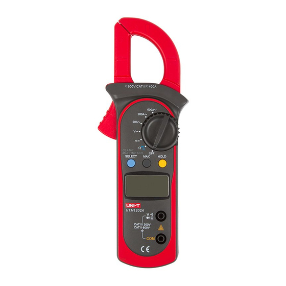
UT202A Operating Manual The Meter Structure (see figure 1) (figure 1) 1. Input Terminals 2. LCD Display 3. Functional Buttons 4. Rotary Switch 5. Trigger: press the lever to open the transformer jaws. When the pressure on the lever is released, the jaws will close. -
Page 8: Functional Buttons And Auto Power Off
UT202A Operating Manual Functional Buttons and auto power 1. HOLD Press HOLD to enter and exit hold mode. Press and hold HOLD button while turning on the Meter, auto power off be canceled. 2. MAX Press MAX to start recording and updating of maximum values. - Page 9 UT202A Operating Manual every rotary switch positions. Below table describe which functional buttons can be used on which rotary switch positions Rotary Functional Buttons Switch SELECT HOLD Positions Ω • • • • • • • • 200A • •...
-
Page 10: Display Symbols
UT202A Operating Manual Display Symbols (see figure 2) (figure 2) Meaning Number Indicator for AC voltage or current Indicator for DC voltage The battery is low. Warning: To avoid false readings, which could lead to possible electric shock or personal injury, replace the battery as soon as the battery indicator appears. -
Page 11: Measurement Operation
UT202A Operating Manual Measurement Operation A. DC Voltage Measurement (see figure 3) Warning To avoid harms to you or damages to the Meter from eletric shock, do not attempt to measure voltages higher than 600V AC/DC. To measure DC voltage, connect the Meter as follows: 1. -
Page 12: Ac Voltage Measurement
UT202A Operating Manual Note: When DC voltage measurement has been completed, disconnect the connection between the testing leads and the circuit under test and remove testing leads from the input terminals. B. AC Voltage Measurement (see figure 4) Warning To avoid harms to you or damages to the Meter from eletric shock, do not attempt to measure voltages higher than 600V AC/DC. -
Page 13: Measuring Resistance
UT202A Operating Manual Note: When AC voltage measurement has been completed, disconnect the connection between the testing leads and the circuit under test and remove testing leads from the input terminals. C. Measuring Resistance (see figure 5) Warning To avoid damages to the Meter or to the... -
Page 14: Testing Diodes
UT202A Operating Manual (figure 5) D. Testing Diodes (see figure 6) Warning To avoid damages to the Meter or to the devices under test, disconnect circuit power and discharge all the high-voltage capacitors before testing diodes. To test the diode out of a circuit, connect the Meter as follows: 1. -
Page 15: Testing For Continuity
UT202A Operating Manual Note: ● To remove the objects being tested from the circuit when measuring can obtain a more accurate result. ● When diode testing has been completed, disconnect the connection between the testing leads and the circuit under test and remove testing leads from the input terminals. - Page 16 UT202A Operating Manual 2. Set the rotary switch to and press Ω SELECT button to select measurement mode. 3. The buzzer sounds if the resistance of a circuit under test is less than 10Ω. 4. The buzzer may or may not sounds if the resistance of a circuit under test is more than 10Ω.
-
Page 17: Ac Current Measurement
UT202A Operating Manual F. AC Current Measurement (see figure 8) Warning To avoid electric shock, never measure current while the test leads are inserted into the input terminals and disconnect test leads and tested circuit connection. Never attempt an in-circuit current measuremnet... - Page 18 UT202A Operating Manual (figure 8)
-
Page 19: Specifications
UT202A Operating Manual Specifications A. General Specifications ● Display: 3 1/2 digits LCD display, Maximum display 1999 ● Auto Polarity Display ● Overloading: Display OL or –OL ● Battery Deficiency: Display ● Measurement Speed: Updates 3 times/second. ● Measuremnet Deviation: When the... -
Page 20: Accuracy Specifications
UT202A Operating Manual Accurate Specifications Accuracy: ±(a% reading + b digits), guarantee for 1 year. Operating temperature: 23℃±5℃ Relative humidity: ≤75%R.H Temperature coefficient: 0.1×(specified accuracy) /1℃ A. AC Voltage: Auto ranging Range Resolution Accuracy 2.000V 20.00V 10mV ±(1.2%+5) 200.0V 100mV 600V ±(1.5%+5) -
Page 21: Resistance
UT202A Operating Manual C. Resistance: Auto ranging Range Resolution Accuracy 200.0Ω 100mΩ ±(1.2%+2) 2.000kΩ 1Ω 20.00kΩ 10Ω ±(1%+2) 200.0kΩ 100Ω 2.000MΩ 1kΩ ±(1.2%+2) 20.00MΩ 10kΩ ±(1.5%+2) Remark: ● Overload protection: 600Vp D. Continuity Test Range Resolution Accuracy Around ≤10Ω,the 100mΩ... -
Page 22: Ac Current
UT202A Operating Manual F. AC Current: Auto ranging Range Resolution Accuracy 20.00A 0.01A ±(2.0%+5) 200.0A 0.1A ±(1.5%+5) 600A ±(2.0%+8) Remarks: ● Overload protection: 600A rms ● Frequency Response: 50Hz~60Hz ● Displays effective value of sine wave (mean value response). ●... -
Page 23: Maintenance
UT202A Operating Manual Maintenance This section provides basic maintenance information including battery replacement instruction. Warning Do not attempt to repair or service your Meter unless you are qualified to do so and have the relevant calibration, performance test, and service information. - Page 24 UT202A Operating Manual replace the battery as soon as the battery indicator “ ” appears. Make sure the transformer jaw and the tets leads are disconected from the circuit being tested before opening the case bottom. To replace the battery:.
Need help?
Do you have a question about the UT202A and is the answer not in the manual?
Questions and answers