Table of Contents
Advertisement
Quick Links
Advertisement
Table of Contents

Related Manuals for UNI-T UT232


Summary of Contents for UNI-T UT232
- Page 1 Model UT232 OPERATING MANUAL...
-
Page 2: Table Of Contents
Model UT232: OPERATING MANUAL TABLE OF CONTENTS TITLE PAGE Overview Unpacking Inspection Safety Information Rules For Safe Operation International Electrical Symbols The Meter Structure A.The Meter Front Structure B.The Meter Back and Bottom Structure Functional Buttons Display Symbols Measurement Operation A. - Page 3 Model UT232: OPERATING MANUAL TABLE OF CONTENTS TITLE PAGE A. General Specifications B. Environmental Requirements Accuracy Specifications A. AC Voltage B. Frequency C. AC Current D. Active Power E. Apparent Power F. Reactive Power G. Power Factor H. Phase Angle I.
-
Page 4: Overview
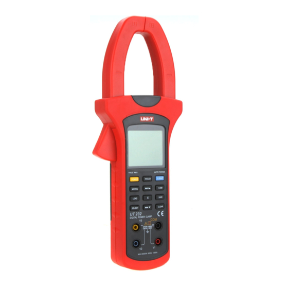
Meter. Yellow Test Lead 1 piece Red Alligator Clip 1 piece Model UT232 is a three phase intelligent handheld Black Alligator Clip 1 piece digital power clamp meter (hereafter referred to as ìthe Blue Alligator Clip 1 piece Meterî) which has both the features of digital current... -
Page 5: Safety Information
Model UT232: OPERATING MANUAL Safety Information in this Operating Manual are explained on page 6. This Meter complies with the standards IEC61010: in Rules For Safe Operation pollution degree 2, overvoltage category (CAT. III 600V, CAT IV 300V) and double insulation. - Page 6 Model UT232: OPERATING MANUAL testing leads away from the input terminals of When opening the battery door, must make sure the Meter and turn the Meter power off. the Meter is power off. Do not carry out the measurement when the When servicing the Meter, use only the same Meterís back case and / or battery door is opened...
-
Page 7: International Electrical Symbols
Model UT232: OPERATING MANUAL International Electrical Symbols AC (Alternating Current) Grounding Double Insulated Warning. Refer to the Operating Manual Deficiency of Built-In Battery Danger of High Voltage Conforms to Standards of European Union... -
Page 8: The Meter Structure
Model UT232: OPERATING MANUAL The Meter Structure Transformer Jaw: designed to pick up the AC and DC current flowing through the conductor. A. The Meter Front Structure (see figure 1) It could transfer current to voltage. The tested conductor must vertically go through the Jaw center. -
Page 9: B.the Meter Back And Bottom Structure
Model UT232: OPERATING MANUAL B. The Meter Back and Bottom Structure button (Sum) (see figure 2) SAVE button (data store button) USB button LIGHT button (auto display backlight button) HOLD button LCD Display Testing Leads (Red, Black, Blue and Yellow) -
Page 10: Functional Buttons
Model UT232: OPERATING MANUAL Functional Buttons Button Operation Performed Below table indicated for information about the functional MENU (secondary display) button operations. AC Current (main display) + AC Voltage (secondary display) Button Operation Performed Active power (main display) + Phase... - Page 11 Model UT232: OPERATING MANUAL Operation Performed Button Operation Performed Button first phase of 3 phase measurement the Meter steps through sum of active MAX/ result. Then carry out second phase power (main display) + sum of reactive power measurement. power (secondary display) and sum of...
- Page 12 Model UT232: OPERATING MANUAL Button Operation Performed Button Operation Performed to exit. The maximum number of data store the Meter steps through sum of active is 99, when it achieves 99, the Meter shows power (main display) + sum of reactive FUL.
-
Page 13: Display Symbols
Model UT232: OPERATING MANUAL Display Symbols Number Symbol Meaning (see figure 3) Data Output is in progress Indicator for DC measurement First phase symbol Second phase symbol Third phase symbol Unit for hour Unit for minute Watt: Sum of Watt The battery is low. - Page 14 Model UT232: OPERATING MANUAL Number Symbol Meaning Minimum reading Analogue Bar Graph Overloading Ruler Maximum reading Indicator for clear the stored reading Ruler negative symbol High voltage symbol Indicates negative reading Indicator for AC voltage or current Indicator for recall the stored...
-
Page 15: Measurement Operation
Model UT232: OPERATING MANUAL Measurement Operation Preparation Press and hold POWER for one second to turn the Meter on. The default range is the last measurement range when you turned off the Meter. Replace the battery as soon as the battery indicator ì... - Page 16 Model UT232: OPERATING MANUAL The display shows the corresponding True RMS The AC Voltage ranges are:15V, 100V, 300V and 600V voltage value and frequency value of each phase. Press MAX/ , the LCD displays MAX, it starts The frequency range is:20Hz~500Hz recording the maximum AC voltage True RMS value.
-
Page 17: Ac Current + Ac Voltage Measurement
Model UT232: OPERATING MANUAL B. AC Current (main display) + AC Voltage The AC current ranges are: 40A, 100A, 400A and 1000A (secondary display) Measurement (see figure 5) The AC Voltage ranges are: 15V, 100V, 300V and 600V To measure AC current + AC voltage, connect the Meter... - Page 18 Model UT232: OPERATING MANUAL True RMS value. Press MIN/ , the LCD displays MAX, it starts recording the minimum AC current True RMS value. Press MAX/ , again to show the present AC current True RMS value. The display shows OL when the current of the tested conductor is higher than 1000A rms.
-
Page 19: Active Power + Phase Angle Measurement
Model UT232: OPERATING MANUAL C. Active Power (main display) + Phase Angle 3. Connecting method (see figure 6, 7, 8): (secondary display) Measurement The active power ranges are: 40A, 100A, 400A and 1000A The phase angle ranges are: 0∞ ~360∞... - Page 20 Model UT232: OPERATING MANUAL Insert red test leads to V1 input terminal. Insert blue test leads to V2 input terminal Insert yellow test leads to V3 input terminal and connecting it to every live wire of the 3 phase. Insert black test leads to COM input terminal and connect it to the neutrual wire of the 3 phase.
- Page 21 Model UT232: OPERATING MANUAL Insert red test leads to V1 input terminal. Insert blue test leads to V2 input terminal Insert yellow test leads to V3 input terminal and connect it to every live wire of the 3 phase. Blue...
- Page 22 Model UT232: OPERATING MANUAL Insert red test lead to V1, V2 or V3 input terminal corresponding to one of 2 or 3 phase Insert black test leads to COM input terminal. Connecting the two test leads to live and neutual wires.
- Page 23 Model UT232: OPERATING MANUAL 4. When measuring 3 phases 4 wires or 3 phases After sum up the current power measurement value 3wires:(see figure 9, 10, 11, 12, 13, 14, 15) of the first phase, then press SELECT to choose the...
- Page 24 Model UT232: OPERATING MANUAL After sum up the current power meaursuremnt value After sum up the current power measurement value of the second phase, then press SELECT again to of the third phase, finally press SELECT again to choose the third phase 3, as figure 13.
- Page 25 Model UT232: OPERATING MANUAL The maximum power is 600kW of single phase, OL Note will be displayed when it is over than that. The When there is no input or single phase, the Meter maximum range is 1800kW of three phase sum of displays OL.
-
Page 26: Apparent Power + Reactive Power Measurement
Model UT232: OPERATING MANUAL D. Apparent Power (main display) + Reactive Power 4. When measuring 3 phase 4 wires: (secondary display) Measurement (see figure 17, 18, 19) Press SELECT to choose the first phase Warning see figure 17. To avoid damages to the Meter or harms to you, do you measure higher than AC voltage 600V rms and AC current 1000A rms. - Page 27 Model UT232: OPERATING MANUAL The double display shows the second phase value When measuring 3 phase 3 wires: of apparent power kVA and reactive power Kvar. The first phase and secodn phase operating Press SELECT again to choose the third phase method is same as three phase 4 wires.
-
Page 28: Power Factor + Phase Angle Measurement
Model UT232: OPERATING MANUAL E. Power Factor (main display) + Phase Angle Press SELECT to choose the first phase (secondary display) Measurement see figure 20. Warning To avoid damages to the Meter or harms to you, do you measure higher than AC voltage 600V rms and AC current 1000A rms. - Page 29 Model UT232: OPERATING MANUAL The double display shows the second phase value 5. When measuring 3 phase 3 wires: of power factor PF and phase angle PG. The first phase and second phase operating Press SELECT again to choose the third phase method is same as three phase 4 wires.
-
Page 30: Active Energy + Time Measurement
Model UT232: OPERATING MANUAL F. Active Energy (main display) + Time (secondary display) Measurement Warning To avoid damages to the Meter or harms to you, do you measure higher than AC voltage 600V rms and Figure 23 AC current 1000A rms. - Page 31 Model UT232: OPERATING MANUAL The maximum readinng of acitve energy is 9999kWh. OL will be displayed when the reading is over than that. 5. MAX/ and MIN/ are not valid when measuring active energy. 6. Press CLEAR to reset the time.
-
Page 32: True Rms Measurement And Average Value Measurement
Model UT232: OPERATING MANUAL True RMS Measurement and Average Value Input Wave PK-PK 0-PK Measurement Sine 2.828 1.414 1.000 0.900 The True RMS measurement method can measure PK-PK accurately the effective value of non-sine wave input sine commute (whole wave) signal. -
Page 33: Specifications
Model UT232: OPERATING MANUAL Specifications Sampling: 3 times per second. Max. Jaw Size: 55mm diameter. A. General Specifications Analogue Bar Graph Maximum Voltage between any Terminals and Power: 4 x 1.5V battery (LR6) grounding: Refer to different range input protection Dimensions: 303mm x 112mm x 39mm voltage. -
Page 34: Environmental Requirements
Model UT232: OPERATING MANUAL B. Environmental Requirements The Meter is suitable for indoor use. Altitude: Operating: 2000m Storage: 10000m Temperature and humidity: Operating: ~ 30 ( 85%R.H) ~ 40 ( 75%R.H) ~ 50 ( 45%R.H) Storage: ~ +60 ( 85%R.H) Safety/ Compliances: IEC 61010 CAT.III 600V,... -
Page 35: Accuracy Specifications
Model UT232: OPERATING MANUAL Accurate Specifications Accuracy: (a% reading + b digits), guarantee for 1 year. Operating temperature: 23 Operating humidity: 45~75%R.H A. AC Voltage (True RMS) Range Resolution Accuracy Allowable Maximum overload protection voltage Input Impedance 100V 0.1V (1.2%+5) -
Page 36: Ac Current
Model UT232: OPERATING MANUAL C. AC Current (True RMS) Range Resolution Accuracy Allowable Maximum overload protection current 100A 0.1A 400A (2%+5) 1000A RMS 1000A D. Active Power ( W=V x A x COS Voltages Range Current / Voltage 100V 300V 600V 0.60kW... -
Page 37: Apparent Power
Model UT232: OPERATING MANUAL E. Apparent Power (VA = V x A) Voltages Range Current / Voltage 100V 300V 600V 0.60kVA 4.00kVA 12.00kVA 24.00kVA 100A 1.50kVA 10.00kVA 30.00kVA 60.00kVA Current Range 400A 6.00kVA 40.00kVA 120.0kVA 240.0kVA 1000A 15.00kVA 100.0kVA 300.0kVA 600.0kVA... -
Page 38: Reactive Power
Model UT232: OPERATING MANUAL F. Reactive Power (Var = V x A x SIN Voltages Range Current / Voltage 100V 300V 600V 0.60kVar 4.00kVar 12.00kVar 24.00kVar 100A 1.50kVar 10.00kVar 30.00kVar 60.00kVar Current Range 400A 6.00kVar 40.00kVar 120.0kVar 240.0kVar 1000A 15.00kVar 100.0kVar... -
Page 39: Power Factor
Model UT232: OPERATING MANUAL G. Power Factor (PF = W / VA) Range Accuracy Resolution Measuring Condition 0.3~1 The minimum measuring current 10A 0.022 0.001 (capacitive or inductive) The minimum measuring voltage 45V 0.3~1 Measuring current less than 10A OR... -
Page 40: Active Energy
Model UT232: OPERATING MANUAL MAINTENANCE I. Active Energy (kWh) This section provides basic maintenance information Range Accuracy Resolution including battery replacement instruction. 1~9999kWh (3%+2) 0.001kWh Warning Remarks: Do not attempt to repair or service your Meter unless Allowable maximum overload protection voltage:... -
Page 41: Replacing The Battery
Model UT232: OPERATING MANUAL high temperature, explosive, inflammable and strong Warning magnetic field. To avoid false readings, which could lead to possible B. Replacing the Battery (see figure 24) electric shock or personal injury, replace the battery as soon as the battery indicator ì... - Page 42 Model UT232: OPERATING MANUAL *END* This operating manual is subject to change without notice.
- Page 43 Model UT232: OPERATING MANUAL Copyright 2007 Uni-Trend Group Limited. All rights reserved. Manufacturer: Uni-Trend Technology (Dongguan) Limited Dong Fang Da Dao Bei Shan Dong Fang Industrial Development District Hu Men Town, Dongguan City Guang Dong Province China Postal Code: 523 925...
Need help?
Do you have a question about the UT232 and is the answer not in the manual?
Questions and answers