Table of Contents
Advertisement
Quick Links
Download this manual
See also:
User Manual
Advertisement
Table of Contents

Related Manuals for Campbell EC155


Summary of Contents for Campbell EC155
- Page 1 Product Manual EC155 O Closed-Path Gas Analyzer Revision: 11/18 Copyright © 2010 – 2018 Campbell Scientific, Inc.
- Page 2 Limited Warranty “Products manufactured by CSI are warranted by CSI to be free from defects in materials and workmanship under normal use and service for twelve months from the date of shipment unless otherwise specified in the corresponding product manual. (Product manuals are available for review online at www.campbellsci.com.) Products not manufactured by CSI, but that are resold by CSI, are warranted only to the limits extended by the original manufacturer.
- Page 3 Campbell Scientific company serves your country. To obtain a Returned Materials Authorization (RMA) number, contact CAMPBELL SCIENTIFIC, INC., phone (435) 227-9000. Please write the issued RMA number clearly on the outside of the shipping container. Campbell Scientific’s shipping address is: CAMPBELL SCIENTIFIC, INC.
- Page 4 Periodically (at least yearly) check electrical ground connections. • WHILE EVERY ATTEMPT IS MADE TO EMBODY THE HIGHEST DEGREE OF SAFETY IN ALL CAMPBELL SCIENTIFIC PRODUCTS, THE CUSTOMER ASSUMES ALL RISK FROM ANY INJURY RESULTING FROM IMPROPER INSTALLATION, USE, OR MAINTENANCE OF TRIPODS, TOWERS, OR ATTACHMENTS TO TRIPODS AND TOWERS SUCH AS SENSORS, CROSSARMS, ENCLOSURES, ANTENNAS, ETC.
-
Page 5: Table Of Contents
Table of Contents PDF viewers: These page numbers refer to the printed version of this document. Use the PDF reader bookmarks tab for links to specific sections. 1. Introduction ..............1 2. Precautions ..............1 3. Initial Inspection ............2 4. - Page 6 Appendices A. Filter Bandwidth and Time Delay ......A-1 B. Useful Equations ........... B-1 C. EC155 Sample Cell and Intake Maintenance ..C-1 Cleaning Sample Cell ............... C-1 Cleaning Intake Tube ............... C-1 C.2.1 Detaching the Vortex Intake ............. C-1 C.2.2 Dust Blowout ................
- Page 7 6-1. Bypass tube and filter assembly ............12 6-2. Exploded view of the EC155 and bypass tube and filter assembly ..12 6-3. Exploded view of mounting newer design EC155 gas analyzer (EC155 sample cell serial numbers 2000 and greater) and CSAT3A sonic head (CSAT3A serial numbers 2000 and greater);...
- Page 8 Thumbscrews above sample cell allowing latches to be spun from position A to position B, freeing struts of analyzer....41 9-8. EC155 analyzer and sample cell with shell top open ......42 9-9. Analyzer removed from sample cell and shell ........42 9-10.
-
Page 9: Introduction
The EC155 is an in-situ, closed-path, mid-infrared absorption gas analyzer that measures molar mixing ratios of carbon dioxide and water vapor, along with sample cell temperature and pressure. The EC155 may be used in conjunction with the CSAT3A sonic anemometer, which measures orthogonal wind components and sonic temperature. -
Page 10: Initial Inspection
Do not carry the CSAT3A by the arms or by the strut between the arms. Always hold it by the stem, where the upper and lower arms connect. Also, do not carry the EC155 by the intake. Always hold it by the main body. - Page 11 The EC155 vortex sample cell and the new CSAT3A sonic head (denoted by EC155 sample cell and CSAT3A serial numbers 2000 and greater) became available in January 2016.
-
Page 12: New Design Csat3A (Top) And Old Previous Design Csat3A (Bottom)
EC155 CO and H O Closed-Path Gas Analyzer FIGURE 4-1. New design CSAT3A (top) and old previous design CSAT3A (bottom) -
Page 13: Specifications
Specifications Measurements Features To compute carbon dioxide, water vapor, and sensible heat fluxes using • the eddy-covariance method, the EC155 measures: carbon dioxide mixing ratio water vapor mixing ratio three-dimensional wind speed (requires CSAT3A) sonic air temperature (requires CSAT3A) sample-cell temperature... - Page 14 EC155 CO and H O Closed-Path Gas Analyzer Factory calibrated range 0 to 1000 µmol·mol –1 0 mmol·mol to 37 °C dewpoint –1 Analyzer temp –30 to 50 °C Baro pressure: 70 to 106 kPa performance Zero max drift ±0.55 mg·m ·°C...
-
Page 15: Output Signals
< 30 m·s –1 azimuth angles between ±170° refer to manufacturer’s product brochure or manual for details For EC155 sample cells with serial numbers less than 2000, refer to the EC100 Barometer specifications for sample cell pressure accuracy Output Signals Features... -
Page 16: Physical Description
Zero/Span: 1/4 inch Swagelok Spatial separation between the original EC155 sample cell and CSAT3A sonic head (serial numbers less than 2000) is as follows: total separation: 16.1 cm (6.3 in); longitudinal separation (parallel to sonic x-axis): 15.2 cm (6.0 in); lateral separation (parallel to sonic y-axis): 3.2 cm (1.3... -
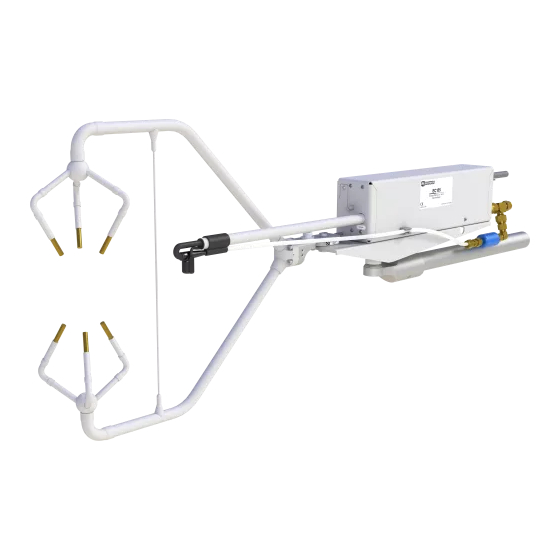
Page 17: Dimensions Of Ec155 Analyzer With Vortex Intake; Sample Cells With Serial Numbers 2000 And Greater
2000) is 3.9 kg (8.5 lbs) Weight of an original-design CSAT3A head (serial numbers less than 2000) is 1.9 kg (4.1 lbs) FIGURE 5-1. Dimensions of EC155 analyzer with vortex intake; sample cells with serial numbers 2000 and greater... -
Page 18: Power Requirements
View compliance documentation at www.campbellsci.com/ec155. Installation The EC155 is supplied with mounting hardware to attach it to the end of a horizontal pipe of 3.3 cm (1.3 in) outer diameter, such as the CM202, CM204, or CM206 crossarm. The EC155 mounting hardware also accommodates an optional CSAT3A sonic anemometer, which places it at the proper position relative to the intake. -
Page 19: Preparation Of Vortex Intake
(for example, the sulfur-containing compounds in viticulture), attempt to mount the EC155 with CSAT3A in a way that reduces the exposure of the sonic transducers of the CSAT3A to saltwater or corrosive chemicals. -
Page 20: Mounting
3. Bolt the EC155 mounting platform to the CM250 leveling mount. 4. Place the EC155 gas analyzer on the mounting platform so the four rubber feet fit into the platform holes, and tighten the captive screws located on the bottom of the platform into the mounting holes on the bottom of the analyzer. -
Page 21: Csat3A Sonic Head (Csat3A Serial Numbers 2000 And Greater); Cables Not Shown
EC155 Gas Analyzer Mounting Platform CM20X Crossarm CM250 Leveling Mount FIGURE 6-3. Exploded view of mounting newer design EC155 gas analyzer (EC155 sample cell serial numbers 2000 and greater) and CSAT3A sonic head (CSAT3A serial numbers 2000 and greater); cables not shown... -
Page 22: Exploded View Of Mounting Older Design Ec155 Gas Analyzer (Ec155 Sample Cell Serial Numbers Less Than 2000) And Csat3A Sonic Head (Csat3A Serial Numbers Less Than 2000)
Mounting Platform CM20X Crossarm CM250 Leveling Mount FIGURE 6-4. Exploded view of mounting older design EC155 gas analyzer (EC155 sample cell serial numbers less than 2000) and CSAT3A sonic head (CSAT3A serial numbers less than 2000). NOTE The CSAT3A sonic anemometer is similar to the CSAT3 and... -
Page 23: Ec100 Enclosure Mounting Bracket Mounted On A Vertical Mast (Left) And A Tripod Leg (Right)
EC155 CO and H O Closed-Path Gas Analyzer to be made by loosening the four nuts and rotating the bracket plates relative to one another. If the necessary angle cannot be reached in the given orientation, the four nuts may be removed and the top plate indexed by 90 degrees to allow the bracket to travel in the other direction (see FIGURE 6-5). -
Page 24: Plumbing
EC155 but the sample cell pressure must be considered. 6.3.2 Pressure The EC155 is designed to be used near ambient pressure, but it will not be damaged by operation under vacuum. The EC155 vortex sample cell includes an absolute pressure sensor to measure sample cell pressure, whereas the... -
Page 25: Filtration
±7 kPa. NOTE If the original EC155 was operated less than 7 kPa from ambient pressure, the user was required to attach a separate, user-supplied pressure sensor. In either version of EC155 sample cell, the pressure of the sample cell is reported as a differential pressure in relation to ambient pressure. -
Page 26: Cross-Sectional View Of Vortex Chamber And Respective Air Flow
EC155 CO and H O Closed-Path Gas Analyzer Sample air enters the larger-diameter side of the vortex chamber where the particles, which are denser than air, are spun to the outside of the vortex and gradually spiral towards the dirty air exit. Meanwhile, clean air is extracted from the vortex’s center and sent to the gas analyzer’s sample cell. -
Page 27: Plumbing Connections
6.3.4 Plumbing Connections There are two connections to the EC155 sample cell: the Zero/Span inlet and Pump outlet, as illustrated in FIGURE 6-10. In the normal mode, a vacuum pump pulls an air sample from the sample intake through the sample cell, and in the case of the vortex intake, it also pulls bypass flow from the vortex. -
Page 28: Pump
6.3.4.2 Pump In normal mode, the EC155 uses a vacuum pump to pull an air sample through the sample cell and vortex bypass. See the discussion on flow and pressure in the previous section for pump requirements. -
Page 29: The Right Figure Shows The Panel After The User Has Done All The Wiring And Made All Connections (Basic Barometer Used)
EC155 CO and H O Closed-Path Gas Analyzer FIGURE 6-11. EC100 electronics front panel. The left figure shows the panel as it is shipped from the factory (enhanced barometer shown). The right figure shows the panel after the user has done all the wiring and made all connections (basic barometer used). -
Page 30: Connection For Csat3A In Ec100 Module
Now insert the cable entry plug that is attached to the large cable of the EC155 gas analyzer head into the vacant slot. Push the connector at the end of the cable onto its mating connector (labeled Gas Analyzer) and tighten the thumbscrews (see FIGURE 6-12). -
Page 31: Ec100 Sdm Output
O Closed-Path Gas Analyzer NOTE Unlike the previous model CSAT3 3D sonic anemometer, the CSAT3A sonic head and the EC155 gas analyzer head have embedded calibration information; meaning that any CSAT3A and any EC155 may be used with any EC100. -
Page 32: Settings
CSAT3A transducers of ice or debris, etc.). Settings Operation of the EC155 can be customized by changing the values of the settings. Factory defaults will work well for most applications, but the user may adjust the settings with a PC using either the ECMon software (see Section 7.3, ECMon... -
Page 33: Details
, for details on using SDM output. (p. 32) Each SDM device on the SDM bus must have a unique address. The EC155 has a factory default SDM address of 1, but may be changed to any integer value between 0 and 14. The value 15 is reserved as an SDM group trigger. -
Page 34: Unprompted Output Rate
EC155 CO and H O Closed-Path Gas Analyzer 7.2.4 Unprompted Output Rate This setting determines the output rate for unprompted output (USB or RS-485, see Section 8.2, USB or RS-485 Output ). If the unprompted output is (p. 32) disabled, this parameter is not used. The factory default output rate is 10 Hz, but it may be set to 10, 20, or 60 Hz. -
Page 35: Temperature Sensor
7.2.10 Fixed Temperature Value If the Temperature Sensor setting is None, the EC155 will use the value of this setting for the sample-cell temperature. This mode is intended for troubleshooting only. -
Page 36: Ec100 Barometer
7.2.12.3 Fixed Pressure Value If the EC100 Barometer setting is None, the EC155 will use the value of this setting for the barometric pressure. This mode is intended for troubleshooting only. In normal operation this setting is not used. -
Page 37: Main Window Of Ecmon
H O Closed-Path Gas Analyzer NOTE For the newer version of the EC155 with vortex intake (sample cells with serial number 2000 and greater), use ECMon version 1.6 or newer. Before connecting the EC100 to the computer, install the USB driver through Device Configuration Utility (available at www.campbellsci.com/downloads). -
Page 38: Ecmon Status Window
EC155 CO and H O Closed-Path Gas Analyzer FIGURE 7-3. Setup window in ECMon. Note that a few of the most rarely used settings have been omitted in Setup window of ECMon for convenience. To access all settings, use Device Configuration Utility. -
Page 39: Device Configuration Utility
Device Configuration Utility may be downloaded at www.campbellsci.com/downloads. The settings associated with the newer version of the sample cell (EC155 sample cell serial numbers 2000 and greater) and the sonic transducer shadow correction require that version 2.12 or newer of Device Configuration Utility be used. -
Page 40: Sdm Output
SDMBeginPort() instruction. On CR3000 and CR5000 dataloggers, the SDM protocol uses SDM-dedicated ports SDM-C1, SDM-C2, and SDM-C3. Each SDM device on the SDM bus must have a unique address. The EC155 has a factory default SDM address of 1, but may be changed to any integer value between 0 and 14 (see Section 7.2.2, SDM Address... -
Page 41: An Example Of Usb Data Output In Terminal Mode
Signature hexadecimal The newer design EC155 sample cell (serial numbers 2000 and greater) uses an absolute pressure sensor to measure sample cell pressure, but the pressure differential relative to ambient pressure is reported. This provides consistency with the older design outputs and is useful in monitoring potential flow constrictions in the intake. -
Page 42: Analog Outputs
ASCII characters, casting them as Long data type. The signature is then calculated on the science data sent from the EC155, starting with CO ending on the counter. All the characters after the counter are not part of the signature. -
Page 43: Maintenance
There are five basic types of maintenance for the EC155/EC100: intake cleaning and filter replacement (vortex bypass filter for newer EC155 sample cells or inline filter for older EC155 sample cells), analyzer cleaning, zero and spanning, replacing analyzer desiccant/scrubber bottles, and factory recalibration. -
Page 44: Replace Vortex Filter
NOTE The filter assembly comes with new ¼ inch Swagelok nuts and is shown in FIGURE 9-1. It may be ordered from Campbell Scientific. Users could also provide their own filters, but the pore size should be small enough to keep particulates from reaching the pump (for example, 25 µm). -
Page 45: Cleaning The Bypass Tubing And Vortex Chamber
EC155 CO and H O Closed-Path Gas Analyzer 9.2.1.2 Cleaning the Bypass Tubing and Vortex Chamber To clean the bypass tubing and vortex chamber follow the steps below. Pull the bypass tube out of the bypass tube sleeve (see FIGURE 9-2). If the tube is visibly dirty, remove the section of tubing by loosening the 1/4-in Swagelok nut on the other end. -
Page 46: A Damp Paper Towel Or Cloth Used To Floss And Clean Inside Surfaces Of Vortex Chamber
During this step, ambient air will rush in and blow dust from the inner walls of the intake tube, which is likely be deposited on the analyzer windows. For this reason, Campbell Scientific recommends performing the dust blowout prior to cleaning... -
Page 47: Inline Intake Filter Replacement
Stop the air flow through the EC155. Locate one of the EC155 intake filters in the mesh pocket of the EC100 enclosure. The Santoprene filter assembly is held in place by friction, remove it by simply pulling on the rain diverter. -
Page 48: Cleaning Analyzer Windows
Stop the air flow through the EC155. Loosen the two captive thumbscrews (one on each end of the EC155), and lift the top portion of the EC155 shell, leaning it back against the lower shell. See FIGURE 9-6. Loosen the thumbscrew on the cable clamp at the back of the analyzer to release the cable, and loosen the two long thumbscrews found above the sample cell. -
Page 49: The Ec155 Analyzer With The Top Shell Open
Rotate the latches back in place to secure the struts down and tighten the long thumbscrews by hand. Position the analyzer cable properly in the cable clamp and tighten the thumbscrew by hand. Put the top portion of the EC155 shell back in place, and tighten the thumbscrews. Top Shell... -
Page 50: Ec155 Analyzer And Sample Cell With Shell Top Open
EC155 CO and H O Closed-Path Gas Analyzer FIGURE 9-8. EC155 analyzer and sample cell with shell top open Optical Window O-ring Optical Window O-ring FIGURE 9-9. Analyzer removed from sample cell and shell... -
Page 51: Zero And Span
Instruction (p. 53) To check and then set the EC155 zero and span, follow the steps below: Connect the EC100 to a PC with the EC100 USB cable, and launch ECMon on the PC. Select the appropriate USB port, and press Connect. - Page 52 (< 0.5 LPM). However, if the tubing is long (for example, if the EC155 is left in place at the top of a tower) it may take a few minutes to flush the tube, and a higher flow rate (> 1 LPM) may be useful to reduce the equilibration time.
-
Page 53: Replacing The Ec155 Desiccant/Co 2 Scrubber Bottles
O is excessive, it may be time to replace the desiccant and CO scrubber bottles (see Section 9.5, Replacing the EC155 Desiccant/CO2 Scrubber Bottles (p. 46) 11. With the zero air still flowing and measurements stabilized, click on the Zero CO and H O button in the Zero/Span window. -
Page 54: Replacing The Ec155 Desiccant/Co Scrubber Bottles
Insert a new bottle lid-first into the analyzer. Firmly screw the plug back in place. CAUTION EC155 instruments sold prior to July 2017 were sold with scrubber bottles that contained strong oxidizing agents. Avoid direct contact with the chemicals inside the bottles. -
Page 55: Factory Recalibration
Gases Group of the Global Monitoring Division/National Oceanographic and Atmospheric Administration in Boulder, CO, USA. After an extended period of time in the field, the EC155 may need to undergo this factory calibration again in order to ensure valid measurements. When... -
Page 56: Data Collection And Data Processing
10. Data Collection and Data Processing Data from the EC155 is collected through the EC100 and then archived onto a datalogger. A common instrument configuration is to program a datalogger to retrieve and collect raw data from the EC155, to be used for post processing, for which various programs have been developed. -
Page 57: Compass Coordinate System, Compass Wind Direction Is 200°. The Sonic Azimuth Of The Anemometer Is 270
EC155 CO and H O Closed-Path Gas Analyzer table and changing the value in the sonic_azimuth field. Note that if the units of the variables are being displayed in the field, the units must be deleted before entering a value. If a new value is attempted to be sent along with the units in the field, then a change will not be made. -
Page 58: Datalogger Programming With Crbasic
EC100 (Dest, SDMAddress, EC100Cmd) Dest is the input variable name in which to store data from the EC155. The length (i.e., number of data elements) of the input variable array will depend on the selected value for EC100Cmd. A value of −99999 will be loaded into Dest(1) if a signature error on SDM data occurs. -
Page 59: Output Modes For Ec100 Instruction
Pressure Differential The newer design EC155 sample cell (serial numbers 2000 and greater) uses an absolute pressure sensor to measure sample cell pressure, but the pressure differential relative to ambient pressure is still reported. This provides consistency with the older design outputs and is useful in monitoring potential flow constrictions in the intake. -
Page 60: Bits In The Sonic Diagnostic Flag
EC155 CO and H O Closed-Path Gas Analyzer TABLE 10-2. Bits in the Sonic Diagnostic Flag Hex Value Decimal Name Function Low Amp Amplitude is too low High Amp Amplitude is too high Tracking Poor signal lock Hi 3 Axis DC... -
Page 61: Ec100Configure() Instruction
This locking will likely result in skipped scans when reconfiguring an EC155. For the EC155 to save settings, it must go through a lengthy write-read-verify process. To avoid saving the settings after each set command, the result code can be used to determine if any settings were modified from their original value. - Page 62 PowerDown: 0 = Gas Head On, 1 = Gas Head Off Unprompted Output Rate: 10 = 10 Hz, 20 = 20 Hz, 99 = motor spin rate EC155 Pressure Sensor Type: 0 = Differential, 1 = Absolute Sonic Transducer Shadow Correction: 0 = Disable, 1 = Enable...
-
Page 63: Configcmd 11 Zero-And-Span Control
O, ConfigCmd 11 is set to 1. After the EC155 completes the zero, it will write the value to –1. The datalogger can poll this value or simply wait for a period of time to allow the zeroing to complete. -
Page 64: Example Crbasic Program
NextScan EndProg 11. Theory of Operation The EC155 is a non-dispersive mid-infrared absorption analyzer. Infrared radiation is generated in the larger block of the analyzer before propagating through a 12 cm sample cell. Chemical species located within the sample cell will absorb radiation at characteristic frequencies. - Page 65 O, radiation at 2.7 µm, corresponding to water’s symmetric stretching vibrational band, is used. The EC155 is a dual wavelength single beam analyzer; thus, rather than using a separate reference cell and detector, the initial intensity of the radiation is calculated by measuring the intensity of nearby, non-absorbing wavelengths (4 µm for CO...
-
Page 66: Filter Bandwidth And Time Delay
The EC100 electronics synchronously sample the gas in the EC155 sample cell and the CSAT3A sonic head. However, delays induced by the intake assembly must be accounted for. The exact delay will depend on the length and size of the intake tubing and the pump flow rate. -
Page 67: Frequency And Amplitude Response Of The Ec100 Filter At Various
±8.33 ms (plus or minus one-half of the inverse of 60 Hz). Alternatively, when sending data to a non-Campbell data acquisition system, the EC100 down-samples its USB and RS-485 outputs to a user-selectable rate of 10, 20, or 60 Hz. -
Page 68: Frequency Response Comparison Of The Ec100 10-Hz Bandwidth And A 50-Msec Moving Average
Appendix A. Filter Bandwidth and Time Delay EC100 10-Hz Filter Compared to 20-msec Moving Average (Amplitude Responses) EC100 10-Hz Bandwidth Filter 10-Hz Bandwidth from a 50-msec Moving Average 0.01 0.001 0.0001 Hertz FIGURE A-2. Frequency response comparison of the EC100 10-Hz bandwidth and a 50-msec moving average TABLE A-1. - Page 69 Appendix B. Useful Equations The following table lists all the variables and constants used in the equations below: Table of Variables and Constants Variable or Constant Description Units ρ Mass Density mg·m –3 ρ O Mass Density g·m –3 ρ Mass Density of Dry Air g·m –3...
-
Page 70: Useful Equations
Appendix B. Useful Equations ρ − (B-5) 1000 Dewpoint from Molar Mixing Ratio (B-6) − (B-7) 61121 1000 ⋅... -
Page 71: Ec155 Sample Cell And Intake Maintenance
C.2.2 and C.2.3, respectively. The older design of the EC155 intake tube is not designed to be removed by the user. If it becomes dirty, it may be cleaned while attached to the sample cell assembly following the guidelines in sections C.2.2 and C.2.3 below. -
Page 72: Identification Of Parts For Detaching Intake With Heater Cable
Appendix C. EC155 Sample Cell and Intake Maintenance Pull the bypass tube out of the bypass tube connection sleeve. Disconnect the heater cable connection. See FIGURE C-1. Loosen the four screws that secure the intake mounting plate in place and remove the plate. -
Page 73: Dust Blowout
Appendix C. EC155 Sample Cell and Intake Maintenance After servicing the intake, it should be reattached following the steps above in reverse order. When reattaching the intake, insert the stainless steel tube back through the small black nut and into the sample cell by pushing directly on the black Santoprene end piece. -
Page 74: Solvent Flush
Appendix C. EC155 Sample Cell and Intake Maintenance Repeat this procedure as needed. When the windows no longer become dirty (CO and H O signal levels do not change) this indicates no more dust is being removed from the intake tube. -
Page 75: Csat3A Orientation
Appendix D. CSAT3A Orientation D.1 Determining True North and Sensor Orientation The orientation of the sonic anemometer negative x-axis is found by reading a magnetic compass and applying the site-specific correction for magnetic declination; where the magnetic declination is the number of degrees between true north and magnetic north. -
Page 76: Online Magnetic Declination Calculator
Appendix D. CSAT3A Orientation FIGURE D-2. Declination angles east of true north are subtracted from 360 to get true north FIGURE D-3. Declination angles west of true north are added to 0 to get true north D.2 Online Magnetic Declination Calculator The magnetic declination web calculator published by NOAA’s Geophysical Data Center is available at the following URL: https://www.ngdc.noaa.gov/geomag-web/#declination. -
Page 77: Online Magnetic Declination Calculator With Inputs And Output For Logan, Ut
Appendix D. CSAT3A Orientation FIGURE D-4. Online magnetic declination calculator with inputs and output for Logan, UT The declination for Logan, UT is 11.47° E. Therefore, true north is 360° - 11.47° = 348.53°. So when looking at a compass at this location, true north is located at 348.53°, not 360°. -
Page 78: Molecular Sieve, Type 13X
Appendix E. Safety Data Sheets (SDS) E.1 Molecular Sieve, Type 13X... - Page 79 Appendix E. Safety Data Sheets (SDS)
- Page 80 Appendix E. Safety Data Sheets (SDS)
- Page 81 Appendix E. Safety Data Sheets (SDS)
-
Page 82: Magnesium Perchlorate
Appendix E. Safety Data Sheets (SDS) E.2 Magnesium Perchlorate... - Page 83 Appendix E. Safety Data Sheets (SDS)
- Page 84 Appendix E. Safety Data Sheets (SDS)
- Page 85 Appendix E. Safety Data Sheets (SDS)
- Page 86 Appendix E. Safety Data Sheets (SDS)
- Page 87 Appendix E. Safety Data Sheets (SDS) E-10...
- Page 88 Appendix E. Safety Data Sheets (SDS) E-11...
- Page 89 Appendix E. Safety Data Sheets (SDS) E.3 Decarbite E-12...
- Page 90 Appendix E. Safety Data Sheets (SDS) E-13...
- Page 91 Appendix E. Safety Data Sheets (SDS) E-14...
- Page 92 Appendix E. Safety Data Sheets (SDS) E-15...
- Page 93 Appendix F. EC155 Packing Information...
- Page 94 Campbell Scientific Worldwide Offices Australia Germany Location: Garbutt, QLD Australia Location: Bremen, Germany Email: Email: info@campbellsci.com.au info@campbellsci.de Website: www.campbellsci.com.au Website: www.campbellsci.de Brazil South Africa Location: São Paulo, SP Brazil Location: Stellenbosch, South Africa Email: andread@campbellsci.com.br Email: sales@csafrica.co.za Website: Website: www.campbellsci.com.br www.campbellscientific.co.za...
Need help?
Do you have a question about the EC155 and is the answer not in the manual?
Questions and answers