
Subscribe to Our Youtube Channel
Related Manuals for Campbell TDR200


Summary of Contents for Campbell TDR200
- Page 1 Product Manual TDR200 TDR200-Based Time-Domain Reflectometry System Revision: 8/19 Copyright © 2016 – 2019 Campbell Scientific...
- Page 3 Quotations for repairs can be given on request. It is the policy of Campbell Scientific to protect the health of its employees and provide a safe working environment, in support of this policy a “Declaration of Hazardous Material and Decontamination”...
- Page 5 PLEASE READ FIRST About this manual Please note that this manual was originally produced by Campbell Scientific Inc. primarily for the North American market. Some spellings, weights and measures may reflect this origin. Some useful conversion factors: Area: 1 in...
- Page 7 • Periodically (at least yearly) check electrical ground connections. WHILE EVERY ATTEMPT IS MADE TO EMBODY THE HIGHEST DEGREE OF SAFETY IN ALL CAMPBELL SCIENTIFIC PRODUCTS, THE CUSTOMER ASSUMES ALL RISK FROM ANY INJURY RESULTING FROM IMPROPER INSTALLATION, USE, OR MAINTENANCE OF TRIPODS, TOWERS, OR ATTACHMENTS TO TRIPODS AND TOWERS...
-
Page 9: Table Of Contents
PDF reader bookmarks tab for links to specific sections. 1. Introduction..............1 2. Precautions ..............1 3. Initial Inspection ............1 TDR200 Packing List ................2 SDM8X50 Packing List ...............2 ENCTDR100 Packing List ..............2 4. QuickStart ..............2 5. Overview ..............6 6. - Page 10 Waveforms collected in a sandy loam using CS610 probe with RG8 connecting cable. Volumetric water content values are 0.10, 0.18, 0.26, 0.30, and 0.37. Solution electrical conductivity is 10.2 dS m –1 .................. 18 CRBasic Example A-1. TDR200 Program Using One CS635 Connected to the SDM8X50 .. A-1...
-
Page 11: Introduction
Upon receipt of the equipment, inspect the packaging and contents for • damage. File damage claims with the shipping company. Check the contents of the shipment (see Section 3.1, TDR200 Packing List • , Section 3.2, SDM8X50 Packing List , and Section 3.3, (p. -
Page 12: Tdr200 Packing List
Terminals for external deep cycle battery QuickStart For simplicity, this section lists steps for a connection between a computer and the TDR200 to monitor a single TDR probe (no multiplexer) using PC-TDR software. TDR200 operation with SDM8X50 multiplexers is described in Section 7.1.3, SDM8X50 , and PC-TDR Help. - Page 13 After the USB driver has been installed, select the Serial Port. Typically, use the default baud rate of 57,600. The SDM Address must match the address of the TDR200. For Noise Rejection Frequency, select 50 Hz or 60 Hz rejection if the system is near AC power lines. The TDR...
- Page 14 TDR200-Based Time-Domain Reflectometry System Select the probe from the list on the left panel, confirm the parent device and device type, and click Ok. In the right pane, enter the Cable Length (required). Cable Length, Window Length, Probe Length, and Probe Offset settings will be...
- Page 15 TDR200-Based Time-Domain Reflectometry System 11. Enter a name for the CRBasic program. Click to specify where to save the program and what type of program to generate. Press Next. 12. Select what is measured and stored, as well as time intervals for...
-
Page 16: Overview
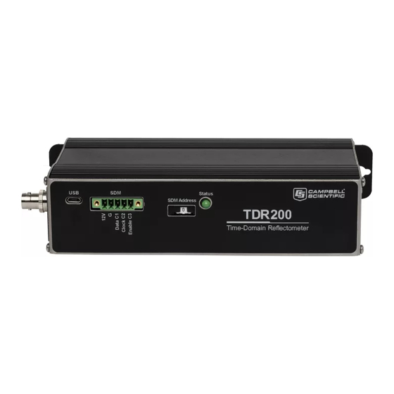
Overview The TDR200 generates a short rise time electromagnetic pulse that is applied to a coaxial system and samples and digitizes the resulting reflection waveform for analysis or storage. It has a single BNC connector for communication with an attached coaxial cable. -
Page 17: Specifications
Appendix C, Terminal Commands (p. C-1) A TDR system consisting of a data logger, TDR200, SDM8X50 multiplexers, 12 V power supply, weatherproof enclosure, and solar panel is used to get automated measurements at prescribed time intervals. A single TDR probe can be connected directly to the TDR200 or multiple probes connected using SDM8X50 coaxial multiplexers. -
Page 18: Electromagnetic Compatibility
Weight: 0.79 kg (1.75 lb) Electromagnetic Compatibility The TDR200 is Πcompliant with performance criteria available upon request. RF emissions are below EN55022 limit. The TDR200 meets EN61326 requirements for protection against electrostatic discharge and surge except for electrostatic discharge on the centre conductor of the panel BNC connector. -
Page 19: Sdm8X50 Major Specifications
FIGURE shows the three multiplexer levels allowing up to 512 probes to be measured. The first level includes the TDR200 and one multiplexer. Up to eight coaxial cables connect to each multiplexer. The coaxial cables can be connected to TDR probes or the next level multiplexers. -
Page 20: Data Logger
(p. 14) information. 7.1.2 TDR200 The TDR200 contains the pulse generator for the signal applied to a TDR sensor. It also digitizes the reflection and applies numerical algorithms for measuring volumetric water content or electrical conductivity. The TDR200 communicates with the data logger using SDM protocol or with a computer using PC-TDR and serial communications. -
Page 21: Power Supply
FIGURE 7-2. Terminal strip adapters for connections to battery Campbell Scientific recommends using the data logger switched 12 V port to power the TDR200. This practice reduces power consumption and resets the TDR200, which provides automatic recovery from system malfunctions and reduces loss of measurement data when a problem exists. -
Page 22: Sdm Communication
This communication protocol adheres to an addressing scheme for all communicating devices. The address selected on the TDR200 must match the SDM address used in the data logger program. The three multiplexer levels (FIGURE 7-1, TDR System... -
Page 23: Soil Probes
Both volumetric water content and electrical conductivity can be measured using fixed spacing 2-rod designs and 3-rod designs. Campbell Scientific manufactures 3-rod TDR probes with rod lengths ranging from 0.075 m to... -
Page 24: Determining Probe Constant, Kp, Using Pc-Tdr
NOTE If the data logger and PC-TDR are simultaneously measuring the TDR200, an error will occur in either the data logger data stream or PC-TDR. The error can be prevented by halting the data logger program while controlling the TDR200 with PC-TDR. To halt the CRBasic program, go to File Control | Stop Program. -
Page 25: Portsconfig Crbasic Instruction
7.2.2 PortsConfig CRBasic Instruction If using a CR800, CR850, or CR1000, the PortsConfig() CRBasic instruction may be needed at the end of the program. When the TDR200 is connected to the data logger for SDM control and SDM8X50 multiplexers are also connected, the PortsConfig() instruction is required to properly configure the control ports. -
Page 26: Cable Length Effect On Water Content Measurement
01138 − 01758 The TDR200 generates a fast rise time pulse that is sent to the connecting cable and probe. Reflections over a specified length of transmission line are sampled and digitized. Discontinuities in cable impedance causes changes in the amplitude of the reflected signal. -
Page 27: Soil Electrical Conductivity Effect On Water Content Measurement
RG8. Careful probe design ensures correct probe impedance giving robust reflections. All TDR probes offered by Campbell Scientific are designed to optimize accuracy when longer cable lengths are used. -
Page 28: Waveforms Collected In A Sandy Loam Using Cs610 Probe With Rg8 Connecting Cable. Volumetric Water Content Values Are 0.10, 0.16, 0.18, 0.21, And 0.25. Solution Electrical Conductivity Is 1.0 Ds M -1
TDR200-Based Time-Domain Reflectometry System probe rods. The attenuation of the signal can affect the accuracy and resolution of water content measurements. FIGURE presents a series of waveforms when a solution with an electrical conductivity of 1.0 dS m is added to a soil which has essentially no salt –1... -
Page 29: Filtering And Averaging
The WaveAvg setting defines the number of waveform reflections averaged by the TDR200 to give a single result. A waveform averaging value of 4 provides good signal-to-noise ratio under typical applications. Under high noise conditions, averaging can be increased. The maximum averaging possible is 128. -
Page 30: Second-Order Bounded Mean Oscillation (Bmo) Algorithm
TDR200 to calculate bulk electrical conductivity. The electrical conductivity calculation uses waveform values for the region immediately before the TDR probe and values from about 200 metres from the TDR200. The value at the location before the probe is used to calculate the applied signal and the 200 metre values are used for the reflected signal. -
Page 31: References
TDR200-Based Time-Domain Reflectometry System References Bilskie, Jim. 1997. “Reducing Measurement Errors of Selected Soil Water Sensors. Proceedings of the International Workshop on Characterization and measurement of the hydraulic properties of unsaturated porous media. 387-396. Giese, K., and R. Tiemann. 1975. “Determination of the complex permittivity from thin-sample time domain reflectometry, Improved analysis of the step response waveform,”... -
Page 33: Example Program
1 on an SDM8X50 multiplexer. The CS635 has a 2 m cable and a 3 m window. CRBasic Example A-1. TDR200 Program Using One CS635 Connected to the SDM8X50 'Sample TDR200 program on CR6 data logger 'Example written for 1 CS635 sensor connected to Channel 1 on an SDM8X50 multiplexer... -
Page 35: Calibration Wizard Tutorial
Appendix B. Calibration Wizard Tutorial The Calibration Wizard is designed to help users: • Calibrate TDR probes to eliminate any probe to probe variability Create probe-specific lengths and offsets for user-made probes • • Quickly determine the appropriate cable and window lengths of any probe •... - Page 36 Appendix B. Calibration Wizard Tutorial A waveform with a default window length of 50 m is then displayed with PC-TDR highlighting where it thinks the probe is found. If the probe is not within the highlighted region, click on the highlighted area in the wizard window and move or scale the region to encompass the entire portion of the probe.
- Page 37 Appendix B. Calibration Wizard Tutorial A detailed measurement is performed and the probe start and end are measured. If the probe reflections are not properly found, click Refresh and attempt to find the beginning and end again. If the waveform is noisy, increase the number of averages or adjust the filtering level (Section 8.4, Filtering and Averaging ).
- Page 38 Appendix B. Calibration Wizard Tutorial The air measurement is now graphed with the beginning and ending of the probe highlighted. If the highlighted region does not properly represent the beginning or end of the probe, either enter new values into the text boxes below the window or use the cursor within the graph window to adjust the width and location of the start and end positions.
- Page 39 Appendix B. Calibration Wizard Tutorial 10. After the Calibration Summary window is displayed, click Finish and the values from the summary will be automatically applied to the probe that was calibrated.
-
Page 41: Terminal Commands
Appendix C. Terminal Commands The TDR200 was developed to be interfaced as a virtual COM port via its physical built-in USB port and to be controlled using third party or user-created application-specific software. In order to use the virtual COM port feature and control the TDR200, a compatible USB driver needs to be installed on the host machine. -
Page 42: About Notation Used In This Document
GVER, GSIG, GVAR, GWA, RSU, and SSU do not require a parameter. For these commands, usage is of this form: [Command]\r\n. For example, to return the current version of the TDR200 operating system the command is “GVER\r\n” Responses to these commands begin with a CR and LF and the response to the command follows. -
Page 43: Error Response
• range. Undefined Value – returned when there is an error in the input • parameter. Initialization Failed – returned if the TDR200 initialization failed. • Unknown Internal • C.4.2 Ack Response Ack responses are returned by the sensor in response to commands that set a parameter in the device. - Page 44 Appendix C. Terminal Commands SDI – Set Distance Usage: SDI[space][value]\r\n – range of value = [-2.0 – 3822.0] Response: \r\n>[space]SDI SWL – Set Window Length Usage: SWL[space][value]\r\n – range of value = [0.0 – 3824.0] Response: \r\n>[space]SWL SPL – Set Probe Length Usage: SPL[space][value]\r\n –...
- Page 45 Appendix C. Terminal Commands DUMP – Show Measurement Parameters: Usage: DUMP\r\n Response: \r\nSetup has been configured as follows: \r\n Vp = [vp value] \r\n Ave = [number of averages value] \r\n Points = [number of points value] \r\n Distance (Cable Length) = [cable length value] \r\n Window Length = [window length value] \r\n...
- Page 46 Appendix C. Terminal Commands GMO – Acquire a new Waveform and return Water Content Value Usage: GMO\r\n Response: \r\n[f.ffff] – where f.ffff is an ASCII representation of a floating point value (4 decimal places) GVER – Get Operating System Version Usage: GVER\r\n Response: \r\n[version] –...
- Page 48 INFO Global Sales & Support Network A worldwide network to help meet your needs Australia Costa Rica Southeast Asia Garbutt, QLD Australia San Pedro, Costa Rica Bangkok, Thailand Location: Location: Location: 61.7.4401.7700 506.2280.1564 66.2.719.3399 Phone: Phone: Phone: info@campbellsci.com.au info@campbellsci.cc thitipongc@campbellsci.asia Email: Email: Email:...
Need help?
Do you have a question about the TDR200 and is the answer not in the manual?
Questions and answers