
Related Manuals for Bacharach Portable Combustion Analyzer


Summary of Contents for Bacharach Portable Combustion Analyzer
- Page 1 Portable Combustion Analyzer (PCA) Instruction 0024-9219 Operation & Maintenance Rev. 10 – May 2010 Product Leadership • Training • Service • Reliability...
- Page 2 Product improvements and enhancements are continuous, therefore the specifications and information contained in this document may change without notice. Bacharach, Inc. shall not be liable for errors contained herein or for incidental or consequential damages in connection with the furnishing, performance, or use of this material.
-
Page 3: Table Of Contents
Contents Contents 1.0 INTRODUCTION ................1-1 1.1 The Portable Combustion Analyzer ........... 1-1 1.2 Displayed Data ................1-2 1.3 PCA Model Configurations ............1-3 2.0 TECHNICAL CHARACTERISTICS ..........2-1 3.0 SETTING UP THE PCA ..............3-1 3.1 Scope .................... 3-1 3.2 PCA Power .................. - Page 4 Contents 4.22 User Name Screens ..............4-28 4.23 Saving Test Data ..............4-29 4.24 Printing Test Data ..............4-30 4.25 Clear Memory Screen ............. 4-32 4.26 Resetting the Microprocessor ..........4-32 5.0 CALIBRATION .................. 5-1 5.1 Sensor Check ................5-1 5.2 Calibration Fixtures ..............
-
Page 5: Introduction
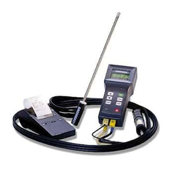
Introduction 1.0 INTRODUCTION 1.1 The Portable Combustion Analyzer The Portable Combustion Analyzer (PCA) (Figure 1-1) is a commercial grade, hand held, combustion efficiency analyzer that is designed for continuous (on demand) sampling of light industrial and residential furnaces, appliances, and boilers. The basic instrument is supplied with a probe, instruction manual, batteries, and carrying case. -
Page 6: Displayed Data
Introduction 1.2 Displayed Data The PCA directly measures, displays, and stores the following data: • Room Temperature in °F or °C (Primary Air/Ambient Temperature) • Flue Gas Oxygen Content in % • Flue Gas Temperature in °F or °C • Flue Gas Carbon Monoxide Content (H Compensated) in ppm (For analyzers having a Carbon Monoxide sensor) •... -
Page 7: Pca Model Configurations
Introduction 1.3 PCA Model Configurations TABLE 1-1. PCA SENSOR CONFIGURATIONS PCA Models Sensors Installed Standard Advanced Part No. Part No. Stack Temp., Draft ( P) Model Model Air Temp. & O 8040 8140 8041 8141 8042 8142 8043 8143 8044 8144 8045... - Page 8 Introduction PCA 30 & 60 with CO and Nitric Oxide Measurement In addition to the features of the basic PCAs with CO measurement, these instruments have the added capability of measuring, displaying, and saving Nitric Oxide (NX) content, as well as calculating a NX level that is referenced to Oxygen.
-
Page 9: Technical Characteristics
Technical Characteristics 2.0 TECHNICAL CHARACTERISTICS The PCA Directly Measures and Displays: • Oxygen content in flue gas in the range of 0.1 to 20.9 % O • Flue gas temperature in the range of 0 to 2192 ºF (–18 to 1200 ºC) •... - Page 10 Technical Characteristics Normal Operating Conditions: Temperature: Analyzer ....32 to 104 ºF (0 to 40 ºC) Probe Tip ....1472 ºF (800 ºC) Max. Humidity: Analyzer ....15 to 90% Relative Humidity, Non-Condensing Air Pressure: Analyzer ....Atmospheric Probe ......10" H O (25 mb) draft max at probe tip Performance: Accuracy:...
- Page 11 Technical Characteristics Power Requirements: Four AA alkaline batteries. Battery backup for the real-time clock, RAM, and bias voltage for the Nitric Oxide sensor is provided by internal lithium batteries. Optional AC Power Supplies (110 VAC & 230 VAC) are also available.
- Page 12 Technical Characteristics NOTES: Instruction 0024-9219...
-
Page 13: Setting Up The Pca
Setup 3.0 SETTING UP THE PCA 3.1 Scope Before using the PCA, you MUST: • Check the batteries or plug in an Optional Power Supply (Section 3.2) • Connect the probe to the analyzer (Section 3.3) • Check the analyzer’s configuration (Section 3.4) 3.2 PCA Power 3.2.1 Checking and Replacing the Batteries A fresh set of batteries is supplied with the PCA. -
Page 14: Using The Optional Power Supply
Setup 3.2.2 Using the Optional Power Supply If an Optional Power Supply is to be used: 1. Connect the output plug of the Optional Power Supply to the analyzer’s power supply jack (Figure 3-2). 2. Plug the Optional Power Supply into an appropriate AC wall outlet. The analyzer will now operate and function normally. - Page 15 Setup Reset Button Room Air / Primary Air Thermocouple (Optional) Power Supply Pressure Reference Port 110V/60Hz (Used in the Measurement 230V/50Hz of Differential Pressure) (Optional) Draft Hose Flue Gas Thermocouple Present only on analyzers Flue Gas equipped with a pressure Hose sensor.
-
Page 16: Configuring The Pca
Setup 3.4 Configuring the PCA The PCA is configured at the factory for the parameters shown below. These parameters, however, can be changed by following the instructions in their associated sections. Function Parameters To Change, Refer to . . . Fuel Natural Gas Section 4.8... -
Page 17: Operation
Operation 4.0 OPERATION 4.1 Key Pad Functions Descriptions of the key pad functions are given below. Note that most of the front panel key pad buttons perform multiple functions as determined by what screen is being displayed at the time. Turns the analyzer ON and OFF. -
Page 18: Sampling Hole Location
Operation 4.2 Sampling Hole Location The analyzer requires that a ½" diameter sampling hole be made in the furnace stack to accommodate the probe stop on the Probe and Hose Assembly. Locate the sampling hole downstream from the last heat exchanger, and upstream from any source of dilution, such as a draft diverter (Figure 4-1). -
Page 19: Performing A Combustion Test
Operation 4.3 Performing a Combustion Test Important! Large rapid changes in the temperature of the analyzer can affect its accuracy. This is important to know if the analyzer is stored in a cold place (such as an unheated vehicle in the winter) and then taken into a warm furnace area. -
Page 20: Installing Probe In The Stack
Operation 4.3.2 Installing Probe in the Stack 1. After making a sampling hole in the stack (Section 4.2), and turning on the analyzer (Section 4.3.1), screw the probe stop supplied with the Probe and Hose Assembly into the sampling hole (Figure 4-2). 2. -
Page 21: Starting A Combustion Test
Operation 4.3.3 Starting a Combustion Test Important! If the burner’s primary-air temperature is not the same as the room temperature, then be sure the Optional Room Air / Primary Air Thermocouple is installed per Section 3.3. 1. With the Combustion Test Screen (Section 4.7) displayed and the probe installed in the stack, press the key to start a combustion test. -
Page 22: Turning Off The Analyzer And Purging The Co Sensor
Operation CAUTION: Do not place a hot probe inside the instrument’s carrying case. Allow the probe to cool before storage. 2. Loosen the thumbscrew on the probe stop; then remove the probe and probe stop from the stack. 3. If data was saved during the combustion test, you can turn off the analyzer and review or print the stored data at a later time as de- scribed in Sections 4.10 and 4.23. -
Page 23: Differential Pressure Measurement
Operation 4.4 Differential Pressure Measurement The difference in pressure (P) between two areas can be measured by using the PCA’s two pressure ports and DRAFT Screen. By using Pres- sure Port 2 (–) as the reference, the pressure applied to Port 1 (+) will be displayed on the DRAFT Screen as the differential pressure between the two ports. -
Page 24: Warm-Up Screen
Operation 4.5 Warm-up Screen BACHARACH, INC. PCA xx WARMUP yy Where: xx = Instrument Model Number yy = Counts down from 60 seconds As soon as the key is pressed, the instrument’s serial number and software version number are displayed for approximately 3 seconds. To continuously display these items, hold down the key at start-up. -
Page 25: Sensor Status Screen
Operation 4.6 Sensor Status Screen BACHARACH, INC. PCA xx WARMUP 0 Where: xx = Instrument Model Number z = Sensor(s) in error If a problem with one or more of the sensors was detected during warmup, the Sensor Status Screen will display an error code for those sensors at the bottom of the screen and wait for operator intervention. -
Page 26: Combustion Test Screen
Operation 4.7 Combustion Test Screen PCA models 10 thru 25, 40 thru 55 PCA models 30, 35, 60, & 65 4.0 CO 4.0 CO 9.5 CF 9.5 NX TA 68.0 TS 374 TA 68.0 TS 374 « « EF 82.6 EA EF 82.6 EA - OR - This screen shows:... -
Page 27: Fuel Selection Screen
Operation 4.8 Fuel Selection Screen «NATGAS FUEL OIL #2 KEROSENE OIL #4 PROPANE OIL #6 COAL This screen is displayed by pressing the key from the Combustion MENU Test Screen, and is used to select the fuel being burned. To select a fuel, first use the keys to move the cursor ( ) in front of the desired fuel, and then press the... -
Page 28: Draft Screens
Operation 4.9 Draft Screens (For PCA Models 15, 25, 35, 45, 55 & 65) The first Draft Screen is displayed by DRAFT repeatedly pressing the key from MENU DISCONNECT DRAFT the Combustion Test Screen. HOSE PRESS ENTER To measure draft, first zero the DRAFT analyzer’s pressure sensor to atmo- RECONNECT DRAFT... -
Page 29: Memory Directory Screen
Operation 4.10 Memory Directory Screen ‘Standard’ PCA Screen ‘Advanced’ PCA Screen MEMORY DIRECTORY MEMORY DIRECTORY «M8 2/24/01 3:45pm «98 2/24/01 3:45pm M9 MEMORY EMPTY 99 MEMORY EMPTY CLEAR MEMORY CLEAR MEMORY The Memory Directory Screen is displayed by repeatedly pressing the key from the Combustion Test Screen. -
Page 30: Memory To Pc Screen
Operation 4.11 Memory to PC Screen (For ‘Advanced’ PCA Models 40, 45, 50, 55, 60 & 65) MEMORY TO PC «TRANSMIT DATA CLEAR MEMORY The Memory To PC Screen is displayed by repeatedly pressing the MENU from the Combustion Test Screen. Use this screen to either transmit all stored memory locations to a computer, or clear all memory locations. - Page 31 Operation Data is transmitted to a computer in ASCII comma-delimited format, which can be captured as a text file and then opened in most commer- cially available spreadsheet programs. Note that each data record con- sists of 20 fields, some of which may be blank for different tests and PCA models as listed in Tables 4-1 &...
- Page 32 Operation TABLE 4-1. COMMA-DELIMITED FIELDS Field Data Name or Value Label in Column Headings Instrument serial number ID line 1 (up to 16 characters) ID line 2 (up to 16 characters) ID line 3 (up to 16 characters) Time of test (hh:mm:ss) TIME Date of test (dd.mm.yyyy) DATE...
-
Page 33: Id Setup Screens
Operation 4.12 ID Setup Screens (For ‘Advanced’ PCA Models 40, 45, 50, 55, 60 & 65) SETUP «ID #1 ID #2 ID #3 This initial ID Setup Screen is displayed by repeatedly pressing the MENU key from the Combustion Test Screen. Use this screen to edit three lines of customer information (e.g., the customer’s name, location, and burner reference number). - Page 34 Operation Press to save the selected character and advance to the next posi- ENTER tion. If you make a mistake, press until the cursor is over the ENTER incorrect character and make your correction by again using the keys. After all the desired characters have been selected, press the key to save the text line and return to the initial ID SETUP Screen.
-
Page 35: Temperature Setup Screen
Operation 4.13 Temperature Setup Screen SETUP TEMPERATURE UNIT «°C °F The Temperature Setup Screen is displayed by repeatedly pressing the key from the Combustion Test Screen. Use this screen to setup the MENU analyzer to display temperature in either °C or °F. To select the temperature unit-of-measure, first use the keys to move the cursor (... -
Page 36: Draft Unit Setup Screen
Operation 4.14 Draft Unit Setup Screen (For PCA Models 15, 25, 35, 45, 55 & 65) SETUP DRAFT UNIT «WC The Draft Unit Setup Screen is displayed by repeatedly pressing the MENU key from the Combustion Test Screen. Use this screen to setup the analyzer to display draft in either millibars (MB), Pascals (PA), or inches- of-water column (WC). -
Page 37: Reference Setup Screen
Operation 4.15 O Reference Setup Screen (For ‘Advanced’ PCA Models 50, 55, 60 and 65) SETUP O2 REFERENCE The O Reference SETUP Screen is displayed by repeatedly pressing the key from the Combustion Test Screen. Use this screen to select the MENU reference level that the analyzer will use to calculate the CO and NX gas levels as referenced to Oxygen. -
Page 38: Language Setup Screen
Operation 4.16 Language Setup Screen SETUP LANGUAGE «ENG The Language Setup Screen is displayed by repeatedly pressing the MENU key from the Combustion Test Screen. Use this screen to select the language displayed on the analyzer. The languages available for selection include English (ENG), Spanish (ESP), and French (FRA). -
Page 39: Display Mode Setup Screen
Operation 4.17 Display Mode Setup Screen (For PCA Models 30, 35, 60 & 65) SETUP DISPLAY «CO NX CF NF The Display Setup Screen is displayed by repeatedly pressing the MENU from the Combustion Test Screen. Use this screen to select whether the Combustion Test Screen will display the measured values of Carbon Monoxide and Nitric Oxide (CO and NX), or the calculated values of these gases (CF and NF) referenced to Oxygen. -
Page 40: Time / Date Setup Screen
Operation 4.18 Time / Date Setup Screen SETUP «TIME 03:12:45 pm DATE 02/24/01 The Time/Date Setup Screen is displayed by repeatedly pressing the MENU key from the Combustion Test Screen. Use this screen to enter the cur- rent time and date as follows: Use the keys to move the cursor ( ) in front of the TIME or DATE... -
Page 41: Printer Setup Screen
Operation 4.19 Printer Setup Screen SETUP «IR - HP PRINTER IR - IRDA RS232 The Printer Setup Screen is displayed by repeatedly pressing the MENU key from the Combustion Test Screen. Use this screen to choose the type of connection and printer being used. IR-HP: Infrared connection to a printer manufactured by Hewlett Packard, which uses their proprietary infrared communica-... -
Page 42: Calibration / Maintenance Password Screen
Operation 4.20 Calibration / Maintenance Password Screen PCA models 10 thru 35 PCA models 40 thru 65 CALIBRATION MAINTENANCE «PASSWORD «PASSWORD Where: xxx = Password number The Calibration / Maintenance Password Screen is displayed by repeat- edly pressing the key from the Combustion Test Screen. From here a MENU three-digit password must be entered to access the PCA 10 thru 35’s Calibration Menu Screen (Section 5.3), or a PCA 40 thru 65’s Mainte-... -
Page 43: Maintenance Screen
Operation 4.21 Maintenance Screen (For PCA Models 40, 45, 50, 55, 60 & 65) MAINTENANCE «CALIBRATION USER NAME The Maintenance Screen is displayed after entering the correct password in the Maintenance Password Screen. Use this screen to either enter the analyzer’s Calibration Menu Screen or User Name Screen. -
Page 44: User Name Screens
Operation 4.22 User Name Screens (For PCA Models 40, 45, 50, 55, 60 & 65) USER NAME «LINE 1 LINE 2 LINE 3 This initial User Name Screen is displayed after selecting USER NAME from the Maintenance Screen. Use this screen to either enter or edit three lines of user-name information. -
Page 45: Saving Test Data
Operation Press to save the selected character and advance to the next posi- ENTER tion. If you make a mistake, press until the cursor is over the wrong ENTER character and make your correction by again using the keys. After all the desired characters have been selected, press to save the text line and return to the initial User Name Screen. -
Page 46: Printing Test Data
Operation 4.24 Printing Test Data 4.0 CO 12 HLD DRAFT 9.5 NX 15 NG DRAFT – 0.25 WC TA 68.0 TS 374 «P HOT SPOT 374 °F «P EF 82.6 EA Before printing, ensure that the correct connection and printer has been selected per Section 4.19. - Page 47 Operation When using a serial printer: 1. First connect the analyzer to the printer using the optional RS-232 cable (see Figure 4-6). 2. Set the printer’s communication parameters to 9600 baud, 8 data bits, 1 stop bit, no parity, and no handshaking. 3.
-
Page 48: Clear Memory Screen
Operation 4.25 Clear Memory Screen CLEAR MEMORY «E The Clear Memory Screen is accessed from either the Memory Directory Screen (Section 4.10) or the Memory to PC Screen (Section 4.11). To clear all memory locations, use the keys to move the cursor ( ) in front of the clear (C) function, and then press the key. -
Page 49: Calibration
Calibration 5.0 CALIBRATION NOTE: Bacharach recommends that the PCA be calibrated by your nearest Bacharach Service Center. Calibration, however, can be performed in the field if your facility has the necessary equipment and qualified personnel to perform the procedures described in the sections that follow. -
Page 50: Calibration Fixtures
Calibration 5.2 Calibration Fixtures A gas and a draft fixture will be required to perform the various calibra- tion procedures described in this manual. Material Required: • Calibration Kit (Refer to Section 8.2) • Calibration Gas Cylinder (Refer to Section 8.2) •... -
Page 51: Calibrate Menu Screen
Calibration 5.3 Calibrate Menu Screen «TS-ZERO CALIBRATE TS-SPAN TA-ZERO TA-SPAN DRAFT The Calibrate Menu Screen is displayed after entering either the correct password in the Calibration Password Screen for ‘standard’ PCAs, or the Maintenance Password Screen and selecting CALIBRATION from the Maintenance Screen for ‘advanced’... -
Page 52: Calibrate Ts-Zero
Calibration 5.4 Calibrate TS-Zero Material Required: • Thermocouple Simulator (K-type) Range: 0 to 600 °F Accuracy: ±0.5 °F Procedure: 1. With the analyzer turned off, first plug the simulator’s K-type connec- tor into the T-STACK jack (Figure 3-2); then turn on the analyzer and wait for its warm-up cycle to complete. -
Page 53: Calibrate Ts-Span
Calibration 5.5 Calibrate TS-Span Material Required: • Thermocouple Simulator (K-type) Range: 0 to 600 °F Accuracy: ±0.5 °F Procedure: 1. With the analyzer turned off, first plug the simulator’s K-type connec- tor into the T-STACK jack (Figure 3-2); then turn on the analyzer and wait for its warm-up cycle to complete. -
Page 54: Calibrate Ta-Zero
Calibration 5.6 Calibrate TA-Zero Material Required: • Thermocouple Simulator (K-type) Range: 0 to 600 °F Accuracy: ±0.5 °F Procedure: 1. With the analyzer turned off, first plug the simulator’s K-type connec- tor into the T-AIR jack (Figure 3-2); then turn on the analyzer and wait for its warm-up cycle to complete. -
Page 55: Calibrate Ta-Span
Calibration 5.7 Calibrate TA-Span Material Required: • Thermocouple Simulator (K-type) Range: 0 to 600 °F Accuracy: ±0.5 °F Procedure: 1. With the analyzer turned off, first plug the simulator’s K-type connec- tor into the T-AIR jack (Figure 3-2); then turn on the analyzer and wait for its warm-up cycle to complete. -
Page 56: Calibrate Nx
Nitric Oxide gas, however, unless your facility has the necessary gas cylinders and personnel trained in the handling of toxic gases, we recommend that the Nitric Oxide sensor be spanned by an authorized Bacharach Service Center. Material Required: • Calibration Gas Fixture (Section 5.2) •... -
Page 57: Calibrate Co
Calibration 5.9 Calibrate CO (For PCA Models 20, 25, 30, 35, 50, 55, 60 & 65) Material Required: • Calibration Gas Fixture (Section 5.2) • Gas Cylinder, 500 ppm CO in air (Refer to Section 8.2) • Gas Cylinder, CO (1000 ppm) and H (1000 ppm) in Nitrogen (Refer to Section 8.2) Procedure:... - Page 58 Calibration 7. Turn off the flow of CO calibration-gas; then remove the calibration- gas cylinder from the calibration fixture. 8. Attach a CO/H calibration-gas cylinder to the calibration fixture; then adjust the regulator of the calibration fixture for a flowmeter reading of approximately 2 SCFH.
-
Page 59: Calibrate Draft
Calibration 5.10 Calibrate Draft (For PCA Models 15, 25, 35, 45, 55 & 65) Material Required: • Calibration Fixture (Section 5-2) • Bellows (adjustable) • Micromanometer Range: ±8 in. H O column (±20 mb) Accuracy: ±0.01 in. H O column (±0.025 mb) Procedure: Important! In Step 1, do not connect the draft calibration fixture to the analyzer until the Calibrate Draft Screen has... - Page 60 Calibration NOTES: 5-12 Instruction 0024-9219...
-
Page 61: Maintenance
Maintenance 6.0 MAINTENANCE 6.1 Routine Maintenance Routine maintenance of the analyzer consists of: replacing the batteries, cleaning the probe, draining the water trap, replacing the water trap filter, and performing periodic calibration checks to ensure that the analyzer is providing accurate readings. •... -
Page 62: Disassembly
Maintenance 6.2 Disassembly Perform the following when a maintenance procedure calls for removing the case, printed circuit board, pump, or sensors: 1. Remove the batteries (Section 3.2.1) 2. Place the analyzer face down on a work surface, then remove the unit’s four rear-case screws. - Page 63 Maintenance BATTERY COMPARTMENT BIAS BATTERY FUSE CO PCB NX PCB CARBON NITRIC MONOXIDE OXIDE SENSOR SENSOR (OPTIONAL) (OPTIONAL) PUMP MTG. SCREWS OXYGEN SENSOR PUMP – BLACK PARTICULATE FILTER DRAFT SENSOR (OPTIONAL) Figure 6-2. PCB and Sensors Instruction 0024-9219...
-
Page 64: Cleaning The Probe
Maintenance 6.3 Cleaning the Probe The Probe Tube and the Probe Body will become dirty under normal use (the water trap’s filter element should prevent soot from reaching the analyzer’s internal components). If the probe assembly is not kept clean, it could become clogged and restrict the flow of gas to the analyzer, resulting in incorrect readings and calculations. -
Page 65: Water Trap/Filter Assembly Maintenance
Maintenance 6.4 Water Trap/Filter Assembly Maintenance The Water Trap / Filter Assembly removes water condensate from the gas sample, and also prevents soot from contaminating the internal compo- nents of the analyzer. Drain the water condensate after every use. Procedure: 1. -
Page 66: Replacing The Particulate Filter
Maintenance 6.5 Replacing the Particulate Filter The internal particulate filter (Figure 6-2) prevents small dust and dirt particles from entering and damaging the pump. Depending on your environmental conditions, it is recommended to change the particulate filter and fitting approximately every six months, or sooner if it becomes clogged. -
Page 67: Replacing The Oxygen Sensor
Maintenance 6.6 Replacing the Oxygen Sensor Replace the Oxygen Sensor when it has expired (when the analyzer’s automatic O calibration fails and the unit displays the message “O2- Sensor Error”). NOTE: A "O2-SENSOR ERROR" displayed in the Sensor Status Screen does not necessarily mean that the sensor has expired. -
Page 68: Replacing The Nitric Oxide Sensor
Maintenance 6.7 Replacing the Nitric Oxide Sensor (For PCA Models 30, 35, 60 & 65) Replace the Nitric Oxide sensor when it has expired (can no longer be calibrated). NOTE: A "NX-SENSOR ERROR" displayed in the Sensor Status Screen does not necessarily mean that the sensor has expired. -
Page 69: Replacing The Nitric Oxide Sensor Bias Battery
Maintenance 6.7.2 Replacing the Nitric Oxide Sensor Bias Battery A single lithium battery, located on the Nitric Oxide printed circuit board (see Figure 6-2), applies a constant bias voltage to the Nitric Oxide sensor even while the instrument is turned off. This battery has a life expectancy of at least 2 years. -
Page 70: Replacing The Carbon Monoxide Sensor
Maintenance 6.8 Replacing the Carbon Monoxide Sensor (For PCA Models 20, 25, 30, 35, 50, 55, 60 & 65) Replace the Carbon Monoxide sensor when it has expired (can no longer be calibrated). NOTE: A "CO-SENSOR ERROR" displayed in the Sensor Status Screen does not necessarily mean that the sensor has expired. -
Page 71: Replacing The Carbon Monoxide Sensor Filter
Maintenance 6.8.1 Replacing the Carbon Monoxide Sensor Filter To increase the life of the Carbon Monoxide sensor, it is recommended its red filter be replaced once a year . Procedure: 1. Remove the Carbon Monoxide sensor per Section 6.8. 2. Pry the red filter from the Carbon Monoxide sensor and replace it with a new one. -
Page 72: Replacing The Pump Assembly
Maintenance 6.9 Replacing the Pump Assembly Replace the Pump Assembly if it is found to be defective. Equipment Required: • " Flat Blade Screw Driver • No. 1 Phillips Screw Driver • Pump Assembly (Refer to Section 8.1) Procedure: 1. Remove the analyzer’s rear case and lay it aside (refer to Section 6.2). 2. -
Page 73: Troubleshooting
All other repairs should be performed by an authorized Bacharach Ser- vice Center. Any repairs performed by an unauthorized service organiza- tion will void the analyzer’s warranty and release Bacharach, Inc. of any implied or written product liability. Before returning your analyzer for repair, you may be able to determine and resolve a problem using the Troubleshooting Guide in Section 7.3. -
Page 74: Error Codes
Troubleshooting 7.2 Error Codes If one of the following messages or symbols is displayed, refer to Section 7.3 Troubleshooting Guide for information on how to correct the error. O2 - SENSOR ERROR Sensor not connected, or is expired, or was exposed to combustion gases during warmup. -
Page 75: Troubleshooting Guide
7.3 Troubleshooting Guide The following table lists the most common analyzer faults, causes and remedies. For help with any problem not discussed here, please contact the nearest Bacharach Service Center per Section 8.3. TABLE 7-1. TROUBLESHOOTING GUIDE Fault Probable Cause & Remedy Analyzer completely nonfunc- a. - Page 76 Sensor was exposed to pressure appears in the Sensor Status outside of its detectable range. Screen. b. Sensor defective. Return analyzer to Bacharach for repair. a. Calibration was attempted while T-STACK OR T-AIR SENSOR sampling combustion gases. ERROR code appears in the Sensor Status Screen.
- Page 77 Troubleshooting TABLE 7-1. TROUBLESHOOTING GUIDE (Cont.) Fault Probable Cause & Remedy “****” appears in one or more The field’s associated sensor is not value fields. installed. “- - - -” appears in one or more value a. The analyzer is not able to calcu- fields of the Combustion Test late a numerical value based on Screen.
- Page 78 Fault Probable Cause & Remedy Backlight will not turn on. Backlight LED burned out. Return to Bacharach for repair. Batteries do not last 10 hours. Cold temperature is reducing bat- tery capacity. To obtain longer oper- ating time, keep analyzer warm.
-
Page 79: Parts & Service
Parts & Service 8.0 PARTS & SERVICE 8.1 Replacement Parts Item Description Part No. (Figure 8-1) Battery Cover 0024-0784 Screw, Case Housing 0501-3824 Screw, Pump Mounting 0501-3822 Oxygen Sensor 0024-0788 Carbon Monoxide Sensor 0024-0789 Nitric Oxide Sensor 0024-0881 Carbon Monoxide Sensor Filter 0024-0863 Nitric Oxide Sensor Filter 0024-0862... -
Page 80: Accessories
Parts & Service 8.2 Accessories Description Part No. STANDARD ACCESSORIES: Battery, “AA” Alkaline 0204-0004 Complete Probe and Hose Assembly (Gas & Draft) 0024-3004 Instruction Manual 0024-9219 Plastic Carrying Case 0024-1078 OPTIONAL ACCESSORIES: Ambient Thermocouple, 10 ft. K-type 0104-1797 Ambient Thermocouple, 1 in. K-type 0104-1798 Bent Probe Tip 0024-8039... - Page 81 Parts & Service Figure 8-1. Replacement Parts (1 of 3) Instruction 0024-9219...
- Page 82 Parts & Service FUSE – BLACK Figure 8-1. Replacement Parts (2 of 3) Instruction 0024-9219...
- Page 83 Parts & Service Figure 8-1. Replacement Parts (3 of 3) Instruction 0024-9219...
-
Page 84: Service Centers
Bacharach, Inc. 621 Hunt Valley Circle New Kensington, PA 15068 Phone: 724-334-5051 Fax: 724-334-5723 Email: help@bacharach-inc.com Canada Bacharach of Canada, Inc. 20 Amber St. Unit #7 Markham, Ontario L3R SP4 Canada Phone: 905-470-8985 Fax: 905-470-8963 Email: bachcan@idirect.com Instruction 00 24-9219... -
Page 85: Appendix A - Display Screen Translations
Appendix A APPENDIX A Display Screen Translations English French Spanish Warm Up Screen BACHARACH, INC. BACHARACH, INC. BACHARACH, INC. PCA nn PCA nn PCA nn Warmup nn ECHAUFFEMENT nn CALENTAMIENTO nn Sensor Status Screen (Errors) NO ERRORS DETECTED PAS D D'ERREUR RELEVEE... - Page 86 Appendix A English French Spanish Saving Memory Screen SAVING MEMORY GARDE LOCATION SALVANDO EN MEMORIA LOCATION nn MEMOIRE nn LOCALIZACION nn Memory Directory Screen MEMORY DIRECTORY LISTE MEMOIRE DIRECTORIO MEM MEMORY EMPTY MEMOIRE VIDE MEMORIA VACIA CLEAR MEMORY EFFACER MEMOIRE BORRAR MEMORIA Draft Memory Screen DRAFT MEM...
- Page 87 Appendix A English French Spanish Time/Date Setup Screen SETUP PROGRAMME SETUP TIME HEURE HORA DATE DATE FECHA Printer Setup Screen SETUP PRINTER PROGRAMME PRINTER SETUP PRINTER IR - HP IR - HP IR - HP IR - IRDA IR - IRDA IR - IRDA RS232 RS232...
- Page 88 Appendix A English French Spanish Calibrate TA-Span Screen CALIBRATE TA-SPAN CALIBRER TA PORTEE CALIBRAR TA-SPAN MEASURED MESUREE MEDIDO APPLIED APPLIQUEE APLICADO BAD CALIBRATION ENTRY ERREUR D'ETALONNAGE CALIBRACION-INCORRECTA Calibrate NX Screen CALIBRATE NX CALIBRER NX CALIBRAR NX MEASURED MESUREE MEDIDO APPLIED APPLIQUEE APLICADO BAD CALIBRATION ENTRY...
-
Page 89: Appendix B - Printout Translations
[Line 1: user name] [Line 2: user name] [Line 2: user name] [Line 2: user name] [Line 3: user name] [Line 3: user name] [Line 3: user name] BACHARACH, INC. BACHARACH, INC. BACHARACH, INC. PCA 65 PCA 65 PCA 65 SN: xxxxxx... - Page 90 Appendix B NOTES: Instruction 0024-9219...
- Page 91 World Headquarters 621 Hunt Valley Circle, New Kensington, PA 15068 Ph: 724-334-5000 • Fax: 724-334-5001 • Toll Free: 800-736-4666 Website: www.mybacharach.com • E-mail: help@mybacharach.com Printed in U.S.A.
Need help?
Do you have a question about the Portable Combustion Analyzer and is the answer not in the manual?
Questions and answers