Bacharach Fyrite Pro Quick Start Manual
Hide thumbs
Also See for Fyrite Pro:
- Brochure (15 pages) ,
- Operation & maintenance manual (60 pages) ,
- Operation & maintenance manual (64 pages)
Table of Contents
Advertisement
Quick Links
This Guide provides basic operating and maintenance information for
Fyrite Pro Model 100/105/110/120/125. Detailed information concerning
the analyzer's operation, set up, calibration, maintenance, and parts list is
contained in Instruction 0024-9395.
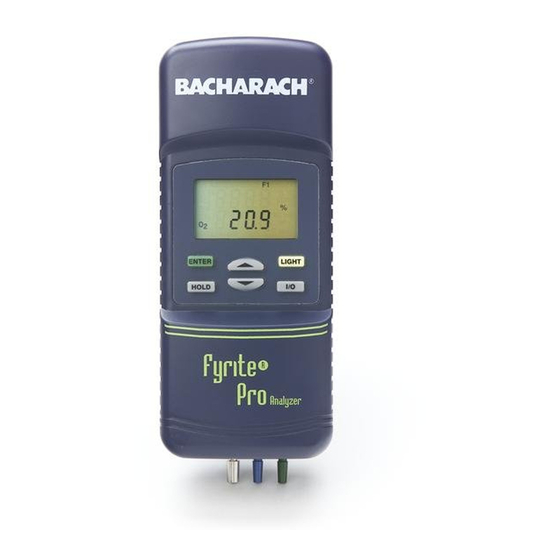
Analyzer Turn On and Warm Up
1. Depending on the analyzer's model
number, connect the probe's sample-
gas hose and, if used, its draft hose
and thermocouple connector to the
bottom of the analyzer as shown in
Figure 1.
If the optional Combustion-Air
Thermocouple is being used, plug it
into the T-AIR connector.
Quick Start Guide 0024-9396
Figure 1. Analyzer Connections
Fyrite
Pro
®
Rev. 8 – May 2010
Advertisement
Table of Contents

Related Manuals for Bacharach Fyrite Pro


Summary of Contents for Bacharach Fyrite Pro
-
Page 1: Quick Start Guide
Quick Start Guide 0024-9396 Rev. 8 – May 2010 This Guide provides basic operating and maintenance information for Fyrite Pro Model 100/105/110/120/125. Detailed information concerning the analyzer’s operation, set up, calibration, maintenance, and parts list is contained in Instruction 0024-9395. - Page 2 Fyrite Pro Quick Reference Guide 2. Turn ON the analyzer by pressing its I/O button and observe that a series of three Warm-Up Screens are displayed. The first screen identifies the model number of the analyzer, the next screen shows the software revision number, while the last screen counts down the warm-up time from either 10 or 60 seconds.
-
Page 3: Measuring Draft
Fyrite Pro Quick Reference Guide 2. For the Model 100/105, the CO or CO & Draft Screen should al- ready be displayed. For the Model 120/125, push the ENTER button to display the CO & O Screen. Model 100 Model 105 Model 120/125 3. - Page 4 Fyrite Pro Quick Reference Guide Performing a Combustion Test using the Model 110/120/125 Important: The probe must be at room temperature before performing the following steps. 1. Perform one of the following: • Model 110/120 – Before turning ON the analyzer, its probe must be located in the area containing the burner’s combustion-air...
- Page 5 Fyrite Pro Quick Reference Guide 5. Insert the probe into the flue-gas stream of the appliance being tested as described below: Forced Air Furnace – When testing atmospheric burner or grav- ity vented, forced air heating equip ment with a clamshell or section- al heat exchanger design, test each of the exhaust ports at the top of the heat exchanger.
- Page 6 Fyrite Pro Quick Reference Guide 80% Eff. Fan Assist or Power Vented Furnace/Boiler 90% Eff. Condensing Furnace/Boiler Atmospheric or Gravity Vented Boiler Instruction 0024-9396...
- Page 7 Fyrite Pro Quick Reference Guide 6. After turning ON the analyzer and selecting the appropriate fuel, press the button to display the Stack Temperature & Effi- ciency Screen. 7. Position the probe in the flue-gas stream to obtain the hottest “Stack”...
-
Page 8: Run Mode Screens
Fyrite Pro Quick Reference Guide Run Mode Screens Figures 2A thru 2E show the order in which the screens are displayed by pressing the ENTER and buttons after the analyzer warms-up and enters its Run Mode. The top screen in each figure is the one that appears immediately after the analyzer completes its warm-up cycle. - Page 9 Fyrite Pro Quick Reference Guide Fuel Select: F1 = Natural Gas F2 = Oil #2 F3 = LPG F4 = Kerosene Ambient / Combustion Air Temperature Stack Temperature & Efficiency & Excess Air Figure 2C. Model 110 Run Mode Screens...
- Page 10 Fyrite Pro Quick Reference Guide Fuel Select: F1 = Natural Gas F2 = Oil #2 F3 = LPG F4 = Kerosene CO & CO Air Free Ambient / Combustion Air Temperature Stack Temperature & Efficiency & Excess Air Figure 2D. Model 120 Run Mode Screens...
- Page 11 Fyrite Pro Quick Reference Guide Fuel Select: F1 = Natural Gas F2 = Oil #2 F3 = LPG F4 = Kerosene CO & O CO Air Free Ambient / Combustion Air Temperature Temperature Differential Stack Temperature & Efficiency & Excess Air CO &...
-
Page 12: Operating Tips
Fyrite Pro Quick Reference Guide Operating Tips • When an analyzer is brought in from a cold vehicle, let it warm up slowly to minimize condensation. Temperatures below freezing will not damage the analyzer; however, bringing a cold analyzer into a warm, humid environment may cause condensate to form inside the case. -
Page 13: Using The Backlight
Fyrite Pro Quick Reference Guide CO Channel Zero (Model 100/105/120/125) If the CO channel is set up for manual zero (refer to Sec tion 3.5.3 in Instruction 24-9395), and if the CO Screen shows a value other than zero when sampling fresh air, then zero the CO channel as follows: 1. -
Page 14: Saving Test Data In Memory
Fyrite Pro Quick Reference Guide Saving Test Data in Memory (Model 105/110/120/125) Up to 10 individual sets of test data can be saved in memory as follows: Note: When memory is full, the next reading saved will over- write the oldest reading. -
Page 15: Clearing Saved Test Data
Fyrite Pro Quick Reference Guide 2. Press the or button until the Open Screen is displayed, and then press ENTER to open the memory locations for viewing. The number shown in the second screen represents the most recent memory location where data was stored. -
Page 16: Printing Test Data
Fyrite Pro Quick Reference Guide Printing Test Data Tip: To avoid printing errors, it is important to select the correct protocol per Section 3.5.8 in Instruction 0024-9395 before saving data. Turn ON the printer. Refer to the printer’s instruction manual for detailed operation and maintenance information. - Page 17 Fyrite Pro Quick Reference Guide Notes: When a calcuation cannot be made because of improper data (i.e., oxygen level above 17.9%), four dashes “- - - -” appear in place of the calculated value on both the screen and printout.
-
Page 18: Turning Off The Analyzer & Co Purge
Fyrite Pro Quick Reference Guide Turning OFF the Analyzer & CO Purge Press the I/O button to turn OFF the analyzer. The unit will count down from 5 before turning OFF, thus allowing time for the operator to abort the turn OFF process by press ing the ENTER button. - Page 19 Fyrite Pro Quick Reference Guide Replace the Filter Element when dirty. • Filter Element, P/N 0007-1644 Material Required: • Small Flat Blade Screwdriver Procedure: 1. Disassemble the trap (see Figure 4 or 5). 2. Remove and discard old filter. 3. Install new filter and reassemble trap.
- Page 20 World Headquarters 621 Hunt Valley Circle, New Kensington, PA 15068 Ph: 724-334-5000 • Fax: 724-334-5001 • Toll Free: 800-736-4666 Web site: www.mybacharach.com • E-mail: help@mybacharach.com Printed in U.S.A.
Need help?
Do you have a question about the Fyrite Pro and is the answer not in the manual?
Questions and answers