
Subscribe to Our Youtube Channel
Related Manuals for Friedrich CP05N10A


Summary of Contents for Friedrich CP05N10A
-
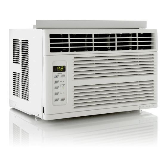
Page 1: Room Air Conditioner
Room Air Conditioner Service and Parts Manual 115 Volts CP05N10A CP05 Svc Parts 2010 (05/10) -
Page 2: Table Of Contents
1. PREFACE ...2 1.1 FEATURES...2 1.2 SPECIFICATIONS ...3 1.3 LOCATIONS OF CONTROLS ...4 2. DISASSEMBLY INSTRUCTIONS 2.1 MECHANICAL PARTS ...4 2.1.1 FRONT GRILLE ...4 2.1.2 CABINET...4 2.1.3 CONTROL BOARD ...4 2.2 AIR HANDLING PARTS ...5 2.2.1 AIR GUIDE UPPER ...5 2.2.2 ORIFICE, TURBO FAN AND FAN ...5 2.2.3 MOTOR ...6 2.2.4 AIR GUIDE ...6... -
Page 3: Preface
This service manual provides various service information, including the mechanical and electrical parts, etc. This room air conditioner was manufactured and assembled under a strict quality control system. The refrigerant is charged at the factory. Be sure to read the safety precautions prior to servicing the unit. -
Page 4: Locations Of Controls
• Everytime you push this button, it will rotate between the COOL, FAN and DRY modes. ON/OFF TIMER ON–When the air conditioner is off, it can be set to automatically come on in 1 to 12 hours from its previous setting. Each touch will increase the timer by 1 hour. -
Page 5: Disassembly Instructions
2. DISASSEMBLY INSTRUCTIONS 2.1 MECHANICAL PARTS 2.1.1 FRONT GRILLE 1. Pull the inlet grille forward. 2. Remove the screw securing the Front Grille. (Fig. 3) 3. Push the grille up from the bottom and pull the top of the grille away from the case to lift the top tabs out of their slots. -
Page 6: Air Handling Parts
2.2 AIR HANDLING PARTS 2.2.1 AIR GUIDE UPPER 1. Disconnect the unit from the power source. 2. Remove the front grille. (Refer to Section 2.1.1) 3. Remove the cabinet. (Refer to Section 2.1.2) 4. Remove the control panel. (Refer to Section 2.1.3) 5. -
Page 7: Motor
2.2.3 MOTOR 1. Disconnect the unit from the power source. 2. Remove the front grille. (Refer to Section 2.1.1) 3. Remove the cabinet. (Refer to Section 2.1.2) 4. Remove the control panel. (Refer to Section 2.1.3) 5. Remove the upper air guide. (Refer to Section 2.2.1) 6. -
Page 8: Compressor
2.3.2 COMPRESSOR 1. Remove the front grille and cabinet. (Refer to Section 2.1) 2. Discharge the refrigerant by using a refrigerant recovery system. 3. Remove the overload protector. (Refer to Section 2.3.1) 4. After discharging the unit completely, unbrace the suction and discharge pipes at the compressor connections. -
Page 9: Power Cord
2.3.6 POWER CORD 1. Disconnect the unit from source of power. 2. Remove the front grille. (Refer to Section 2.1.1) 3. Remove the cabinet. (Refer to Section 2.1.2) 4. Remove a screw that secures control panel to base pan. (Refer to Section 2.1.3) 5. -
Page 10: Evaporator
2.4.2 EVAPORATOR 1. Remove the cabinet. 2. Discharge the refrigerant by using a refrigerant recovery system. 3. Remove the upper air guide . (Refer to Section 2.2.1) 4. After discharging the refrigerant completely, unbraze the interconnecting tube at the condenser connections. - Page 11 Equipment needed: Vacuum pump, charging cylinder, manifold gauge, brazing equipment, pinch-off tool capable of making a vapor proof seal, leak detector, tubing cutter, hand tools to remove components and service valve. CONDENSER (HIGH PRESSURE SIDE) COMPRESSOR EXTERNAL VACUUM PUMP Figure 20A-Pulling Vacuum COMPOUND GAUGE MANIFOLD GAUGE...
-
Page 12: Troubleshooting Guide
2.4.4 ELECTRICAL DATA Line Cord Plug Do not under any circumstances cut or remove the grounding prong from the plug. Power supply cord with 3-prong grounding plug USE OF EXTENSION CORDS Because of potential safety hazards, we strongly discourage the use of an extension cord. However, if you wish to use an extension cord, use a CSA certified/UL-listed 3-wire (grounding) extension cord, rated 15A, 125V. -
Page 13: Piping System
Reference should be made to Figure 21 to follow the refrigerating cycle and the flow of the refrigerant in the cooling cycle. EVAPORATOR COILS COMPLETE LIQUID BOIL OFF POINT COOLED LIQUID PRESSURE DROP ROOM AIR CONDITIONER CYCLE OF REFRIGERATION SUCTION LINE COOL LOW PRESSURE VAPOR ROOM AIR HEAT LOAD MOTOR COMPRESSOR (LIQUID REFRIGERANT) CAPILLARY TUBE Figure 21 —12—... -
Page 14: Troubleshooting Guide
3.3 TROUBLESHOOTING GUIDE In general, possible trouble is classified in two kinds. The one is called Starting Failure which is caused by an electrical defect. The other is Ineffective Air Con- ditioning caused by a defect in the refrigeration circuit and improper application. Unit is running but cooling is ineffective. - Page 15 Check voltage power source. Check control switch setting. Compressor fails to start. Drop of power voltage. Defect of compressor or capacitor. Capacitor check. Replacement. Irregular motor resistance (Ω) Irregular motor insulation (Ω) Replacement of compressor (Motor damaged). Fails to Start Improper thermostat setting Loose terminal...
- Page 16 ROOM AIR CONDITIONER VOLTAGE LIMITS NAME PLATE RATING 115V ± 10% COMPLAINT Fan motor will not run. No power Power supply cord Wire disconnected or connection loose Capacitor (Discharge capacitor before testing.) Will not rotate Fan motor runs. Revolves on overload...
- Page 17 wheel control board —16—...
- Page 18 COMPLAINT Compressor cycles on Fan motor overload. Condenser air flow restriction Condenser fins (damaged) Capacitor Wiring Refrigeration system Insufficient cooling Air filter Unit undersized Excessive noise Blower or fan Copper tubing CAUSE If not running, determine the cause. Replace if required.
-
Page 19: Circuit Diagram
4. CIRCUIT DIAGRAM MEZ62420702 LOCATION (SMPS) 250V/T2A (250V/T3.15A) DESCRIPTION POWER CORD ASSY FAN MOTOR COMPRESSOR CAPACITOR OVERLOAD PROTECTOR —18— (BL) PART NO Q'TY CP05N10A PER SET 67300020 67400116 67301425... -
Page 20: Exploded View
145200 352390-2 567480... -
Page 21: Service Parts List
Louver,Vertical 147582-2 Louver,Vertical 268711-1 PCB Assembly,Display 268711-2 PCB Assembly,Main 35211A Tube Assembly,Suction 352390-1 Guide Assembly,Air 352390-2 Guide Assembly,Air W0CZZ Capacitor,Film,Box W48602 Clamp,Spring CP05N10A 67302931 67303719 67306008 67306107 67304600 67305531 67400167 67305507 67500149 67305532 67300020 67302240 67400116 67303414 67302617 67301900 67302613... - Page 22 Use Factory Certified Parts... FRIEDRICH AIR CONDITIONING CO. Visit our web site at www.friedrich.com Post Office Box 1540 • 4200 N. Pan Am Expressway • San Antonio, Texas 78295-1540 • (210) 357-4400 • FAX (210) 357-4490 CP05 Svc Parts 2010 (05/10)
Need help?
Do you have a question about the CP05N10A and is the answer not in the manual?
Questions and answers