Friedrich CP05 Service & Parts Manual
Chill
115 volts
Hide thumbs
Also See for CP05:
- Installation and operation manual (43 pages) ,
- Service manual (36 pages) ,
- Installation & operation manual (15 pages)

Subscribe to Our Youtube Channel
Related Manuals for Friedrich CP05


Summary of Contents for Friedrich CP05
-
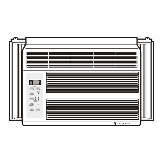
Page 1: Room Air Conditioner
Room Air Conditioner Service & Parts Manual 2014-2015 CP05 Chill 115 Volts THE EXPERTS IN ROOM AIR CONDITIONING 93011400_02... -
Page 2: Table Of Contents
CONTENTS 1. PREFACE 2.4 REFRIGERANT CYCLE ........9 1.1 SAFETY PRECAUTIONS .......2 2.4.1 CONDENSER ..........9 1.2 INSULATION RESISTANCE TEST....2 2.4.2 EVAPORATOR ..........10 1.3 PRODUCT SPECIFICATIONS .......3 2.4.3 CAPILLARY TUBE ........10 1.4 OPERATING INSTRUCTIONS.......4 2.4.4 ELECTRICAL DATA........12 3. TROUBLESHOOTING GUIDE .....12 2. DISASSEMBLY INSTRUCTIONS 3.1 OUTSIDE DIMENSIONS........12 2.1 MECHANICAL PARTS .........5 3.2 PIPING SYSTEM ..........13... -
Page 3: Product Specifications
1.3 PRODUCT SPECIFICATIONS Buyer Model CP05G10A BTU performance (Cooling) 5,450 BTU performance (Heating) 10.7 Dehumid. ( Pts/Hr) Dry Air Flow (CFM) dBA Level (Indoor / Outdoor) 52/56 Est. Cooling Area (SQ.FT) Voltage / 60 Hz Watts (Cooling) Watts (Heating) Rated Amps (Cooling) Rated Amps (Heating) Thermostat Control Thermistor... -
Page 4: Operating Instructions
1.4 OPERATING INSTRUCTIONS CHECK FILTER & FILTER RESET Check Filter: Your ‘Check Filter’ LED will light up after approximately 250 hours of operation, notifying you that your filter needs to be cleaned. Filter Reset: press ‘Filter Reset’ to turn off ‘Check Filter’ light. OPERATION MODE SELECTOR Push the ‘Mode’... -
Page 5: Disassembly Instructions
2. DISASSEMBLY INSTRUCTIONS 2.1 MECHANICAL PARTS 2.1.1 FRONT GRILLE Figure 1 1. Pull the inlet grille forward. 2. Remove the screw securing the Front Grille. (Fig. 3) 3. Push the grille up from the bottom and pull the top of the grille away from the case to lift the top tabs out of their slots. -
Page 6: Air Handling Parts
2.2 AIR HANDLING PARTS Figure 6 2.2.1 AIR GUIDE UPPER 1. Disconnect the unit from the power source. 2. Remove the front grille. (Refer to Section 2.1.1) 3. Remove the cabinet. (Refer to Section 2.1.2) 4. Remove the control panel. (Refer to Section 2.1.3) 5. -
Page 7: Motor
2.2.3 MOTOR 1. Disconnect the unit from the power source. Figure 10 2. Remove the front grille. (Refer to Section 2.1.1) 3. Remove the cabinet. (Refer to Section 2.1.2) 4. Remove the control panel. (Refer to Section 2.1.3) 5. Remove the upper air guide. (Refer to Section 2.2.1) 6. -
Page 8: Compressor
2.3.2 COMPRESSOR 1. Remove the front grille and cabinet. Figure 14 (Refer to Section 2.1) 2. Discharge the refrigerant by using a refrigerant recovery system. 3. Remove the overload protector. (Refer to Section 2.3.1) 4. After discharging the unit completely, unbrace the suction and discharge pipes at the compressor connections. -
Page 9: Power Cord
2.3.6 POWER CORD Figure 18 1. Disconnect the unit from source of power. 2. Remove the front grille. (Refer to Section 2.1.1) 3. Remove the cabinet. (Refer to Section 2.1.2) 4. Remove a screw that secures control panel to base pan. (Refer to Section 2.1.3) 5. -
Page 10: Evaporator
wise. This will keep oil from foaming and being 2.4.2 EVAPORATOR drawn into the vacuum pump. 1. Remove the cabinet. 2. Discharge the refrigerant by using a refrigerant 6-3. Operate the vacuum pump for 20 to 30 min- recovery system. utes, until 600 micron vacuum is obtained. - Page 11 Equipment needed: Vacuum pump, charging cylinder, manifold gauge, brazing equipment, pinch-off tool capable of making a vapor proof seal, leak detector, tubing cutter, hand tools to remove components and service valve. COMPOUND GAUGE MANIFOLD GAUGE CONDENSER SEE INSETS (HIGH PRESSURE SIDE) BELOW COMPRESSOR EVAPORATOR...
-
Page 12: Electrical Data
2.4.4 ELECTRICAL DATA Line Cord Plug Use Wall Receptacle Power Supply Do not under any Use 15 AMP, time circumstances cut or remove the delay fuse, or circuit grounding prong breaker. from the plug. Power supply cord with Standard 125V, 3-wire grounding 3-prong grounding plug receptacle rated 15A, 125V AC USE OF EXTENSION CORDS... -
Page 13: Piping System
3.2 PIPING SYSTEM CONDENSER COILS MOTOR CAPILLARY TUBE TURBO FAN EVAPORATOR COILS Following is a brief description of the important components and their function in what is called the refrigeration system. Reference should be made to Figure 32 to follow the refrigerating cycle and the flow of the refrigerant in the cooling cycle. -
Page 14: Troubleshooting Guide
3.3 TROUBLESHOOTING GUIDE In general, possible trouble is classified in two kinds. The one is called Starting Failure which is caused by an electrical defect. The other is Ineffective Air Con- ditioning caused by a defect in the refrigeration circuit and improper application. Unit is running but cooling is ineffective. - Page 15 Fails to Start Check of circuit breaker Check voltage power source. and fuse. Check control switch Gas leakage of feeler setting. bulb of thermostat. Check control switch. Compressor fails to Fan fails to start. start. Improper wiring. Improper thermostat Drop of power voltage. setting Defect of fan motor or capacitor.
- Page 16 ROOM AIR CONDITIONER VOLTAGE LIMITS NAME PLATE RATING MINIMUM MAXIMUM 115V ± 10% 103.5V 126.5V COMPLAINT CAUSE REMEDY Fan motor will not run. No power Check voltage at outlet. Correct if none. Power supply cord Check voltage to electronic control board. If none, check power supply cord.
- Page 17 COMPLAINT CAUSE REMEDY Fan motor noise. Fan blade If cracked, out of balance, or partially missing, replace it. Blower wheel If cracked, out of balance, or partially missing, replace it. Loose set screw Tighten it. Worn bearings If knocking sounds continue when running replace the motor.
- Page 18 COMPLAINT CAUSE REMEDY Compressor cycles on Fan motor If not running, determine the cause. Replace if overload. required. Condenser air flow Remove the cabinet, inspect the interior surface restriction of the condenser. If restricted, clean carefully with a vacuum cleaner (do not damage fins) or brush.
-
Page 19: Circuit Diagram
4. CIRCUIT DIAGRAM (SMPS) 250V/T3.15A MEZ65238802 Fault Codes Error No. Error Item Error Content CH01 Indoor Air Sensor Error Indoor air sensor open or short EEPROM reading date error CH09 EEPROM CheckSum Error CH34 High Pressure Error As high pressure,comp off over 10 times in 1 hour. —19—... -
Page 20: Exploded View
5. EXPLODED VIEW 749740 267110 130910 559011 W48602 554030 149980 731273 349480 422100 132111-1 132111-2 135312 147582-2 352390-1 147582-1 145200 359012 346811 W48602 152302 352390-2 354210 130410 135303 W0CZZ 552113 352115 264110 567502 352113 237200 554160 268711-2 567480 35211A 550140 238310 268711-1 249950... -
Page 21: Service Parts List
REF # DESCRIPTION PART NO# NOTES 352390-2 GUIDE ASSEMBLY, AIR 67302743 346811 AC MOTOR ASSY SINGLE 67400116 359012 EVAP. FAN, TURBO 67302617 W48602 CLAMP,SPRING 67302500 149980 SHROUD CONDENSOR 67305534 559011 FAN CONDENSOR 67302613 349480 ORIFICE 67303414 352390 GUIDE ASSEMBLY AIR 67302742 749740 SILL PLATE GUIDE... - Page 22 CP05.Svc(06/14)93011400_02(6/14)
Need help?
Do you have a question about the CP05 and is the answer not in the manual?
Questions and answers