Table of Contents

Summary of Contents for Patton electronics 2085RC
- Page 1 RS-232 to RS-485 Converter: Dual Port Rack Mount Card SALES OFFICE Part# 07M2085RC-B Doc# 047052UB (301) 975-1000 Revised 05/11/99 TECHNICAL SUPPORT C E R T I F I E D (301) 975-1007 http://www.patton.com An ISO-9001 Certified Company...
-
Page 2: Table Of Contents
4.4.2 Multipoint Twisted Pair Connection commercial installation. However, there is no guarantee that interfer- ence will not occur in a particular installation. If the Model 2085RC 5.0 Operation ................19 does cause interference to radio or television reception, which can be 5.1 LED Status Monitors... -
Page 3: Ce Notice
Both units support asynchro- nous data rates to 115.2 Kbps over 1 or 2 twisted pairs and support distances to 9.4 miles (19 AWG @19.2 kbps). The Model 2085RC fea- tures 6 easy-to-read front panel LEDs and incorporates Silicon Avalanche Diodes for protection against the damaging effects of near- by lightning strikes and other harmful transients. -
Page 4: Configuration
Figure 1. Model 2085RC board, showing location of configuration switches. “high” impedance of 16K Ohms. By selecting the proper impedance for each drop, there may be up to 50 receivers in one application. Each of the DIP switches on the Model 2085RC function card is a S1-1 Setting 4-position switch. -
Page 5: Switch Setting - Modem A
The setting for switch S1-4 determines whether the Model 2085RC echoes data back to the transmitting device (half-duplex mode only). Switches S2-3 and S2-4 are set together to determine whether the Model 2085RC is in 2-wire or 4-wire operating mode. Note: 2-wire S1-4 Setting mode is half-duplex only. - Page 6 S4-3* 2-Wire/4-Wire 2-Wire 4-Wire The setting for switch S3-2 determines the amount of delay between the time the Model 2085RC “sees” RTS and when it sends S4-4* 2-Wire 4-Wire 2-Wire/4-Wire CTS. Note: RTS/CTS Delay setting should be based upon transmis- *Note: Switches S4-1 and S4-2 must be switched simultaneously.
-
Page 7: Rear Card Configuration
The table below provides a summary of strap functions for both of the rear cards. Following the summary table is a description for each The Model 2085RC has two interface card options: the 1Q11 strap function. (which comes equipped with two RJ-11 ports and two RJ-45 ports) and INTERFACE CARD STRAP SUMMARY TABLE #1 the 1Q45 (which comes equipped with four RJ-45 ports). -
Page 8: Installation
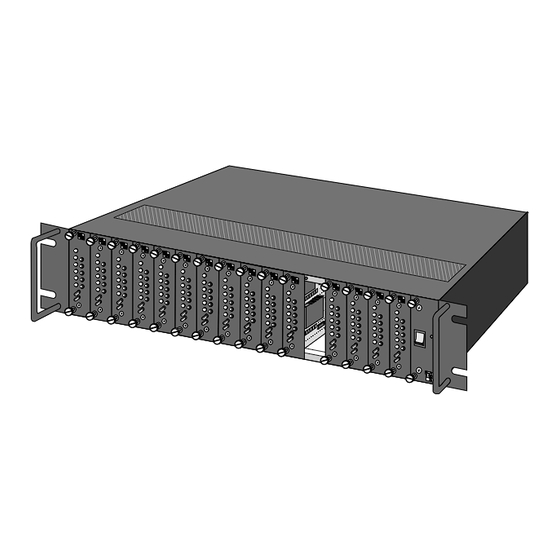
This section describes the functions of the Model 1000R16 rack Because this rear card is designed to function in more applications chassis, tells how to install front and rear Model 2085RC cards into the than the Model 2085RC, this jumper must be installed only in one posi- chassis and provides diagrams for wiring up the interface connections tion. -
Page 9: Rs-232 Connection
NOTE: The Model 2085RC is comprised of a front card and a rear card. The Model 2085RC can only communicate over uncon- The two cards meet inside the rack chassis and plug into each other by ditioned twisted pair wire. -
Page 10: Multipoint Twisted Pair Connection
Call Patton Technical Support for specific distance estimates. The diagram below shows how SIGNAL PIN# PIN# SIGNAL to wire the two-pair cables properly for a Model 2085RC star topology. Note that the ground connection is not needed. † 1-----------------------6 † RCV-... -
Page 11: Operation
0-50°C (32-122°F) 5.2 POWER-UP Altitude: 0-15,000 feet There is no power switch on the Model 2085RC: Power is automat- Humidity: Up to 95% non-condensing ically applied to the 2085RC when its card-edge connector touches the chassis’ mid-plane socket, or when the chassis’ power is turned on. -
Page 12: Appendix B - Cable Recommendations
FACTORY REPLACEMENT PARTS The Patton Model 2085RC rack system features interchangeable The Patton Model 2085RC operates at frequencies of 115kHz or rear half cards, power cords/fuses for international various operating less and has been performance tested by Patton technicians using environments and other user-replaceable parts. -
Page 13: Appendix D - Interface Pin Assignments
APPENDIX D PATTON ELECTRONICS MODEL 2085RC INTERFACE PIN ASSIGNMENTS PATTON MODULAR INTERFACE - 10 Wire RJ-45 Contact Number Circuit Description Not Used Received Line Signal Indicator (CD) 108 / 2 DTE Ready (DTR) Signal Common Received Data Transmitted Data Clear to Send...


Need help?
Do you have a question about the 2085RC and is the answer not in the manual?
Questions and answers