Table of Contents
Advertisement
Quick Links
Advertisement
Table of Contents

Related Manuals for Patton electronics 2026


Summary of Contents for Patton electronics 2026
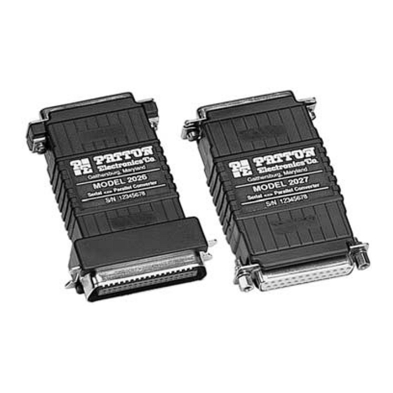
- Page 1 USER MANUAL MODEL 2026 and 2027 Parallel to Serial/ Serial to Parallel Interface Converters Part #07M2026-D SALES OFFICE Doc. #102031U, (301) 975-1000 Rev. E TECHNICAL SUPPORT Revised 1/22/08 (301) 975-1007 An ISO-9001 http://www.patton.com Certified Company...
-
Page 2: Warranty Information
1.1 RADIO AND TV INTERFERENCE The Model 2026 and Model 2027 generate and use radio frequency energy, and if not installed and used properly—that is, in strict accordance with the manufacturer's instructions—may cause interference to radio and television reception. - Page 3 NOTE: Packages received without an RMA number will not be accepted. Patton Electronics' technical staff is also available to answer any questions that might arise concerning the installation or use of your Model 2026 or Model 2027. Technical Support hours: 8AM to 5PM EST, Monday through Friday.
-
Page 4: General Information
DCE/DTE modes. Requiring no AC power, the Model 2026 and 2027 support serial data rates to 38.4 Kbps. For easy configuration, the Model 2026 and Model 2027 feature a convenient set of external configuration switches. -
Page 5: Configuration Switches
Patton Technical Support at (301) 975-1007. 3.1 CONFIGURATION SWITCHES The Model 2026 and 2027 each use a set of eight external DIP switches (see Figure 1) that allow configuration to a wide range of applications. Because all eight switches are in one externally accessible DIP switch package, there is no need to open the case for configuration. -
Page 6: Detailed Switch Settings
9600 bps Data Rate Data Rate The Model 2026 and Model 2027 use a miniature configuration switch package. To configure your unit, use a small screwdriver and gently push each switch to its proper setting. The ON and OFF positions are shown in Figure 2. Default settings for the DIP switches are shown in the table on the following page. - Page 7 Stop Data Parity Model 2027 Data Rate 1200 2400 4800 9600 19200 38400...
- Page 8 Model 2026 or 2027 Your cable Printer Figure 3. Installing the Model 2026 and 2027 Switches 6 through 8: Frequency and Data Rate Switches 6 through 8 determine the frequency and data rate. The following chart shows the settings that may be used:...
-
Page 9: Installation
4.0 INSTALLATION The Patton Model 2026 and 2027 are very simple to install. Once you have configured the DIP switches, just plug your converter in to a standard cable and you’re ready to go. Figure 3 illustrates the proper connections for the Model 2026 and 2027. If you have special-ordered a non-standard connector, your connections may be different. -
Page 10: Operation
“ON/OFF” switch. 5.1 LED STATUS MONITORS The Model 2026 and the Model 2027 feature easy-to-read status LEDs that glow red to indicate the condition of the transmission line. Figure 1 shows the location of these LEDs. The following chart describes the LED’s various functions. -
Page 11: Port Connections
APPENDIX B PATTON MODEL 2026/2027 INTERFACE CONNECTIONS 36 PIN CENTRONICS PARALLEL PORT CONNECTIONS Description Direction Serial to Parallel Parallel to Serial Strobe Output Input Data Bit 0 Output Input Data Bit 1 Output Input Data Bit 2 Output Input Data Bit 3... - Page 12 APPENDIX B (continued) SIGNAL DIRECTIONS Serial Software Flow Serial Hardware Converter Serial Port Serial Data Ctrl. Signal Flow Ctrl Signal Function Connected Flow (XON/XOFF) (DTR, CTS, DSR) Serial to Parallel CTS, DSR Serial to Parallel Parallel to Serial Parallel to Serial CTS, DSR...
- Page 13 APPENDIX C PATTON MODEL 2026 BLOCK DIAGRAM...
- Page 14 APPENDIX D PATTON MODEL 2027 BLOCK DIAGRAM Copyright © Patton Electronics Company All Rights Reserved...
- Page 16 Dear Valued Customer, Thank you for purchasing Patton Electronics products! We do appreciate your business. I trust that you find this user manual helpful. We manufacture one of the widest selections of data communications products in the world including CSU/DSU's, network termination units, powered and self-powered short range modems, fiber optic modems, interface converters, baluns, electronic data switches, data-line surge protectors, multiplexers, transceivers, hubs, print servers and much more.
Need help?
Do you have a question about the 2026 and is the answer not in the manual?
Questions and answers